
Background
When two (2) rail cars are coupled together at high speeds, there is a chance that the forces caused by this hard coupling could damage either rail car. Section 10.7 of the Transportation of Dangerous Goods Regulations (TDGR) restricts the allowable coupling speed of rail cars carrying dangerous goods for which a placard is required (Table 1), and if a coupling event occurs at speeds exceeding this limit, there are requirements to stop use of the rail car until it can be inspected.
Table 1. Maximum coupling speed of rail tank cars as specified by Section 10.7 of the TGDR
| Combined Coupling Mass (kg) | Ambient Temperature | Relative Coupling Speed |
|---|---|---|
| > 150 000 | ≤ -25°C [-13°F] | > 9.6 kph [6 mph] |
| > 150 000 | > -25°C [-13°F] | > 12 kph [7.5 mph] |
| ≤ 150 000 | ≤ -25°C [-13°F] | > 12.9 kph [8 mph] |
| ≤ 150 000 | > -25°C [-13°F] | > 15.3 kph [9.5 mph] |
These regulations are based on finite element (FE) simulations of stub sills and impact modelling conducted by the National Research Council Canada (NRC) in the 1990s at the request of Transport Canada (TC).
Since that time there have been significant advancements in full-scale testing of tank car hard coupling. Most notably, in 2020 the United States (US) Department of Transportation - Federal Railroad Administration (FRA) published their work on full-scale experimental tests of tank car coupling impacts Footnote [1] which provide valuable force, speed, and strain data. There have also been many advancements in computational resources, material modelling and finite element simulation that can be incorporated into rail tank car hard coupling analysis.
This context presents an opportunity to re-assess the effectiveness of TDGR coupling speed limits using the comprehensive material data, real world test results, and software available today.
Objectives
The objective of this study is to investigate whether current TDGR speed limits on rail car coupling are effective at preventing damage from high-speed hard coupling events.
TC requested that NRCan – CanmetMATERIALS create an updated FE model of a rail tank car to simulate coupling impacts, with a particular focus on the stub sill assembly and low temperature effects (down to -40°C).
Limited materials testing was also done to assess the importance of using material properties of A572 steel (a common stub sill material) to model the sub still, rather than assuming the entire tank was made of TC128B steel.
Methods
A full-scale FE model (Figure 1) was developed, validated, and used to simulate hard coupling impacts of rail tank cars. This analysis is based on a simplified model that assumes that the stub sill is in an ideal condition with no embedded flaws in the structure, and weld material is not modeled – it considers the ideal case rather than the worst case and is intended to inform future research.
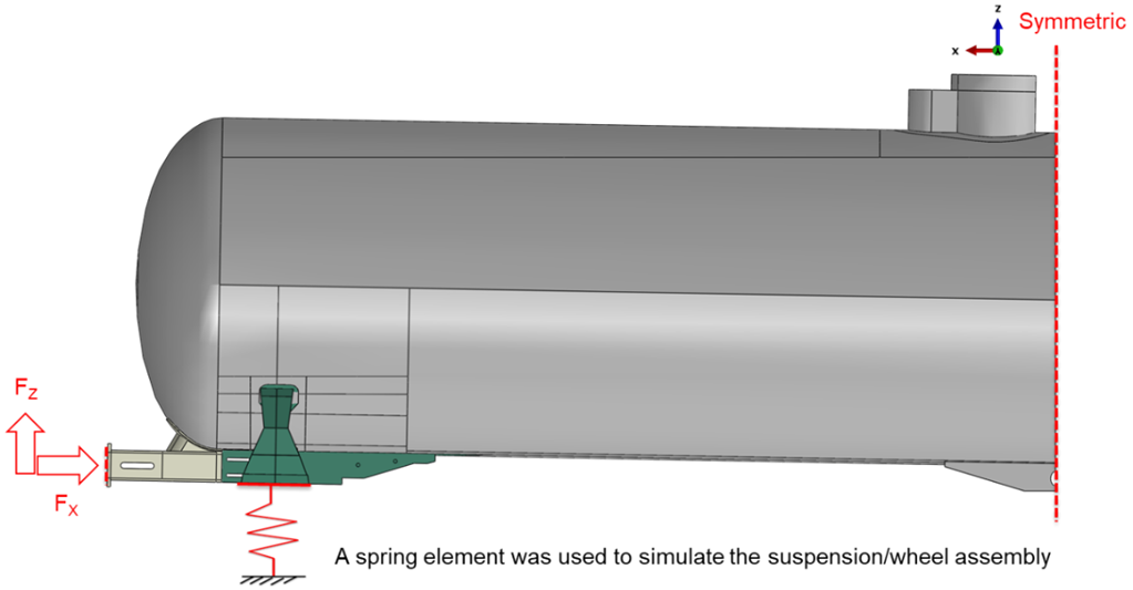
Figure 1. Full-scale tank car (anvil car) finite element model with symmetric boundary conditions.
The material model used in the FE model was based on existing extensive testing of TC128B at various temperatures and strain-rates previously conducted by CanmetMATERIALS Footnote [2]. The FE model was updated to account for brittle fracture at low temperatures using a maximum principal stress criterion. In both cases, the maximum principal stress in the model was monitored and compared with the material strength to determine if plastic deformation or failure occurred.
To examine the effects of the assumption that the entire structure was made of TC128B, limited mechanical testing on a common stub sill material, A572, was done. Tensile testing and Charpy tests at 25⁰C and -40°C were performed on A572 so it could be compared directly to the same data of TC128B.
Full scale test data was provided by FRA Footnote [1] through TC, which was used to calibrate and validate the FE model. Key inputs were coupler forces and the corresponding strains. Table 2 details the eight (8) scenarios used in this study. The FE model was run for each of these eight (8) scenarios at room temperature of 25°C and low temperature of -40°C to generate the resulting impact forces.
Table 2. Impact scenarios provided by the FRA, used to calibrate and validate FE model. Setup is of hammer car striking
| Case | Hammer car | Draft gear | Speed |
|---|---|---|---|
| 1 | Empty | Steel friction | 9.66 kph (6 mph) |
| 2 | Empty | Steel friction | 16.09 kph (10 mph) |
| 3 | Partially Full | Steel friction | 9.66 kph (6 mph) |
| 4 | Partially Full | Steel friction | 16.09 kph (10 mph) |
| 5 | Full | Steel friction | 9.66 kph (6 mph) |
| 6 | Full | Steel friction | 16.09 kph (10 mph) |
| 7 | Full | Twin pack | 9.66 kph (6 mph) |
| 8 | Full | Twin pack | 16.09 kph (10 mph) |
To optimize modelling of a full-scale simulation, while still accurately capturing the influence of small, localized high-stress regions, a two-step modelling strategy was used. First a coarse mesh was used in full-scale simulations to identify areas of high stress regions, then a sub-model with a fine mesh was run on these smaller areas to increase modelling accuracy (Figure 2).
(a)
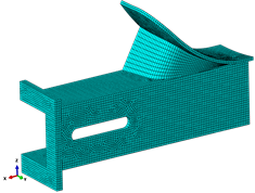
(b)

(c)
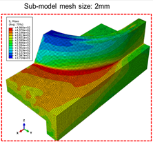
Figure 2. Visualization of the two-step modelling strategy, where a coarse mesh is applied to the stub sill (a), high stress areas are identified (b), then a fine mesh is run to increase accuracy in these areas (c).
Results
The FE analysis results agree well with the test results from the FRA Footnote [1]. Figure 3 shows a representative comparison of experimental and FE analysis-predicted strains at various locations on the tank car.
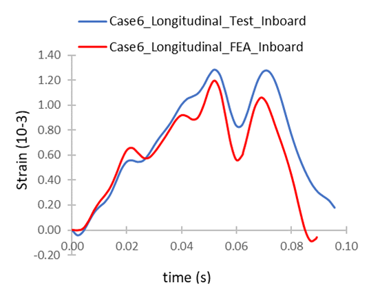
Figure 3: Comparisons of experimental (red) and FEA-predicted (blue) strain for Case 6 (impact speed: 16.09 kph/10 mph, for an in-board strain gauge installed under the car at the end of the stub sill beam.
The results of A572 material testing showed that TC128B performs better, especially for impact toughness. This was not surprising, largely due to the known differences in heat treatment of the two (2) steels – in typical rail tank car construction, TC128B is normalized, whereas A572 is used as-rolled in stub sill construction.
The results of the Charpy testing are particularly important. At -34°C, the CVN (Charpy V-notch toughness, representing fracture toughness) for A572 is approximately 10% lower than TC128B. The load vs. displacement curves (Figure 4) show that although both materials can take similar loads before failing, A572 fails much faster while TC128B “holds on” longer and absorbs more energy before failing. This suggests TC128B is the superior material when considering survivability from impacts. However, the difference is not so significant, therefore the model was simplified by modelling both the tank car and stub sill materials as T128B.
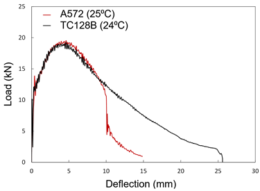
Figure 4. Load vs. displacement curves for A572 (red) and TC128B (black) at 24°C.
The results of the eight (8) cases studied from Table 2 are summarized in Table 3 below by peak stress and strain in the stub sill. No case with a peak load below 1000 kips (4448 kN) developed plastic strain, which corresponds to the 1,000,000-pound compressive load requirement [Footnote 3, Footnote 4] for some freight cars. Only one case with an impact speed of 6 mph exhibited plastic strain, though the magnitude was small enough to be considered negligible. The plastic strains that were seen in the 10 mph cases were very small and localized, signified by the stress observed there surpassing the yield strength of the material. None of the cases experienced damage initiation. There is no indication that a single hard coupling event at these velocities (6-10 mph) would result in damage to a previously undamaged tank car at the temperatures studied (25°C and -40°C).
Table 3. Peak stress and plastic strain from impact scenarios.
| Case | Peak Stress (MPa) | Peak Load | Plastic Strain [25°C/-40°C] |
|---|---|---|---|
| 1 | 382 | 3733 kN / 839 kips | None/None |
| 2 | 601 | 7980 kN / 1793 kips | 3.27e-3/2.40e-3 |
| 3 | 487 | 4845 kN / 1089 kips | 3.82e-5/8.83e-6 |
| 4 | 637 | 9476 kN / 2130 kips | 6.17e-3/4.92e-3 |
| 5 | 230 | 2286 kN / 514 kips | None/None |
| 6 | 560 | 6427 kN / 1445 kips | 1.2e-3/7.20e-4 |
| 7 | 254 | 2511 kN / 565 kips | None/None |
| 8 | 587 | 9178 kN / 2063 kips | 6.53e-3/5.26e-3 |
The strains are slightly lower for the low temperature simulations. This occurs because the lower temperature material is slightly stiffer (higher modulus). The results of the FE simulations do not show increased failure at low temperature at the velocities studied (6 and 10 mph). Preliminary FE analysis into embedded flaws suggest that a clear stress concentration is required in addition to low temperatures for the brittle behaviour to occur.
Locations of high stress were identified in the FE analysis (Figure 5). Two (2) locations coincide with weld lines, with the weld between the head brace and the tank shell being of particular interest.
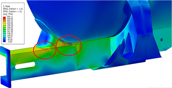
Figure 5. Distribution of Von Mises stresses (shown). The equivalent plastic strain occurred in the same area.
Conclusions
FE analysis results correlate very well with the test results from FRA, suggesting the FE model developed in this study is functional despite the simplifications.
One such simplification, the assumption that stub sills are also made of TC128B, appears to be acceptable for current study objectives. While A572 is brittle compared to TC128B, more significant differences are seen in weld material as an example. The results suggest other areas of additional research would be more beneficial in better understanding stub sill failures, as detailed in the next section.
The modelling gives no indication that a single hard coupling event at these velocities (6-10 mph) would result in damage to a previously undamaged tank car at the temperatures studied (25°C and -40°C). This suggests current coupling speed limits should be effective at preventing damage from isolated, routine coupling.
However, additional research would be needed to build confidence on these findings, particularly at low temperatures, and to investigate why damage occurs in stub sills despite the existing coupling speed limits in the TDGR.
FE analysis results indicate that a clear stress concentration, such as an embedded flaw, is required in addition to low temperatures for the brittle behaviour to occur.
Results show stress concentrations along weld lines, notably at interface between the head brace and the tank shell, are of interest. Welds are, by design, weaker and may be a site of damage initiation and crack propagation.
Preliminary analysis into embedded flaws showed cracks behave differently depending on the type of force. Coupling forces are mostly longitudinal, compressive forces. These tend to close cracks and not cause propagation. Vertical forces, however, cause tensile stresses and shear stresses, which are more problematic for crack propagation. These forces can occur due to coupler height mismatch, sloshing, and long trains.
Future action
Additional research could be done to investigate the causes and key drivers of damage in stub sills. The present conclusions are based on several simplifications, and could benefit from future work such as:
- model harsher impact speeds and temperatures to see when single impacts could lead to damage initiation
- consider crack propagation and damage initiation in an enhanced FE analysis that includes welds
- investigate embedded flaws, compounded with low temperature effects, vertical coupling force, and cyclic loading
- establish critical crack size through damage tolerance analysis and compare to cracks caught in common inspection methods
Report: Finite Element Analysis of Tank Car Hard Coupling (2021)
Authors: McKinley, J. Xue, B. W. Williams, S. Xu, M. Gesing (NRCan—CanmetMATERIALS)
TP Number: 15512E
ISBN: 978-0-660-41612-0
Catalogue Number: T44-3/27-2022E-PDF
Acknowledgements
This project was funded by Transport Canada and conducted by Natural Resources Canada.
Contact us
To obtain a copy of the report, please contact us:
TDG Scientific Research Division
TC.TDGScientificResearch-RecherchescientifiqueTMD.TC@tc.gc.ca
Keywords
TC128B, A572, rail tank car, hard coupling, stub sill, impact modelling, steel properties, material modelling