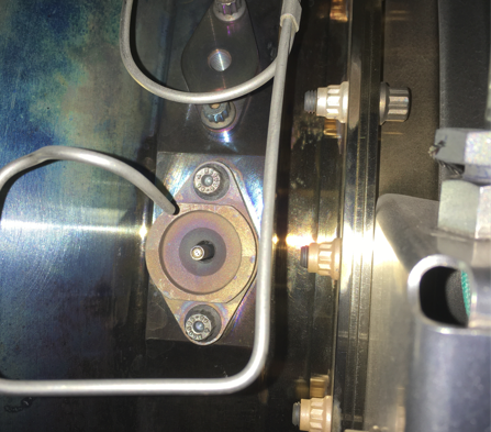
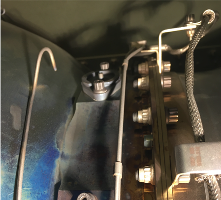
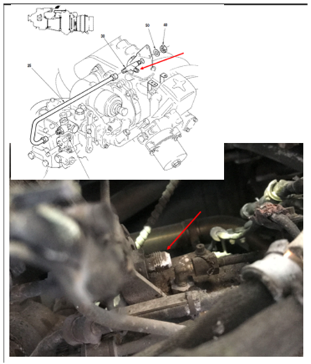
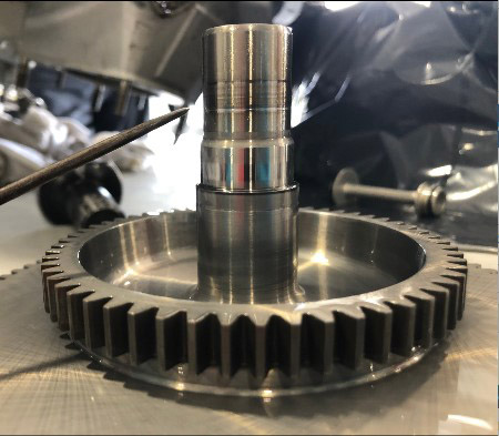
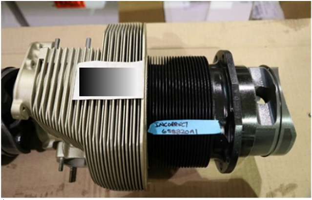
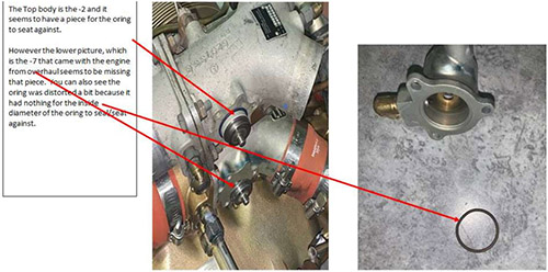
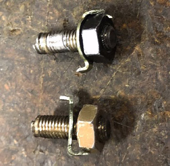
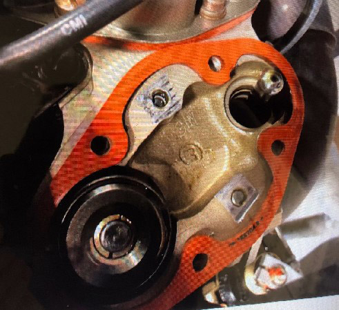
Service Difficulty Reports about engines that either show a trend or should be known by the airworthiness community.
On this page
- Allison
- Austro Engine
- AVCO Lycoming
- CFM International
- Garrett
- General Electric
- Honeywell
- Pratt & Whitney – Canada
- Pratt & Whitney – USA
- Rolls Royce – USA
- Teledyne Continental
- Turbomeca
- Williams
Allison
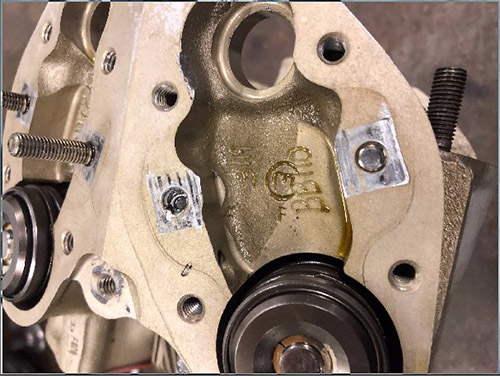
250-C47B Engine Outer Combustion Case Cracked Fuel Nozzle Boss
SDR #: 20160505004
Subject:
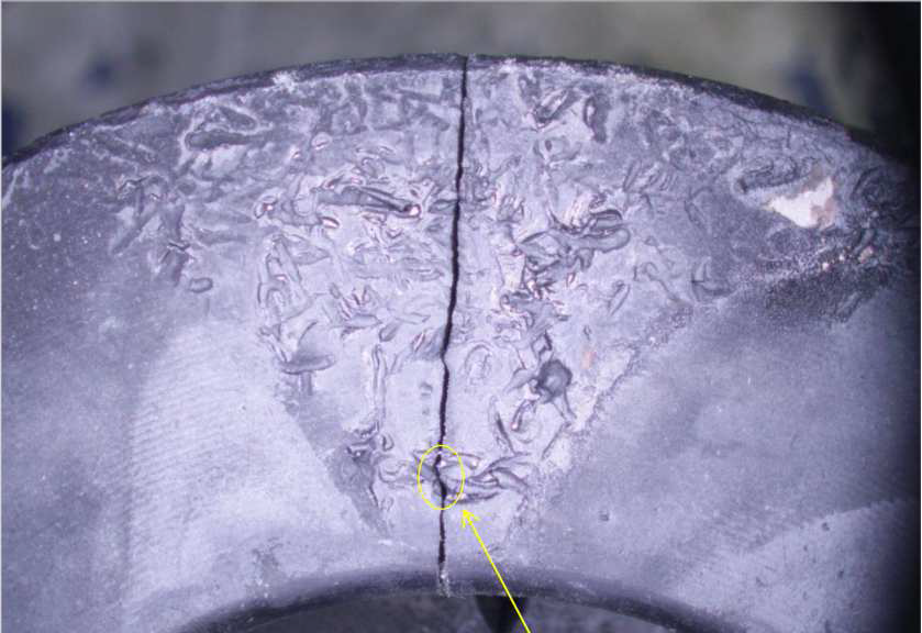
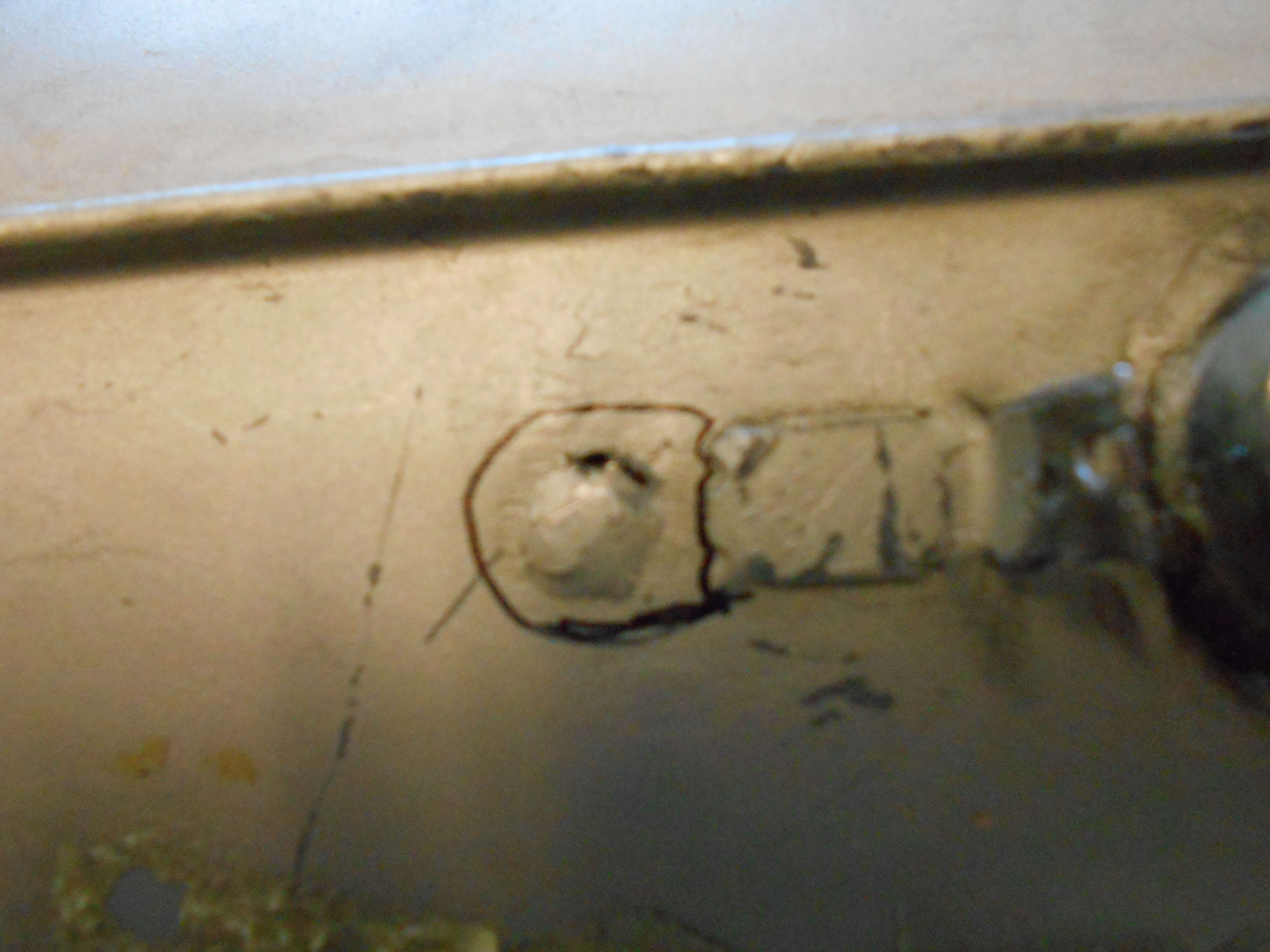
During aircraft startup, the pilot noticed high turbine outlet temperature and shut down the engine. The aircraft maintenance engineer discovered that the fuel nozzle boss was separated from the can at weld/radius.
Transport Canada Comments:
Rolls Royce has acknowledged additional instances of potential outer combustion case cracking by issuing Revision 3 to M250-C47 CEB A-72-7002. The latest revision decreases the interval of the repetitive visual inspection for the weld size at the fuel nozzle boss. Remain vigilant when inspecting this area. Cracking and separation of the fuel nozzle boss could lead to potential power and performance reduction. Additional Alert Commercial Engine Bulletins have been released to also cover the M250-C28, -C30 & -C40 series Roll Royce engines.
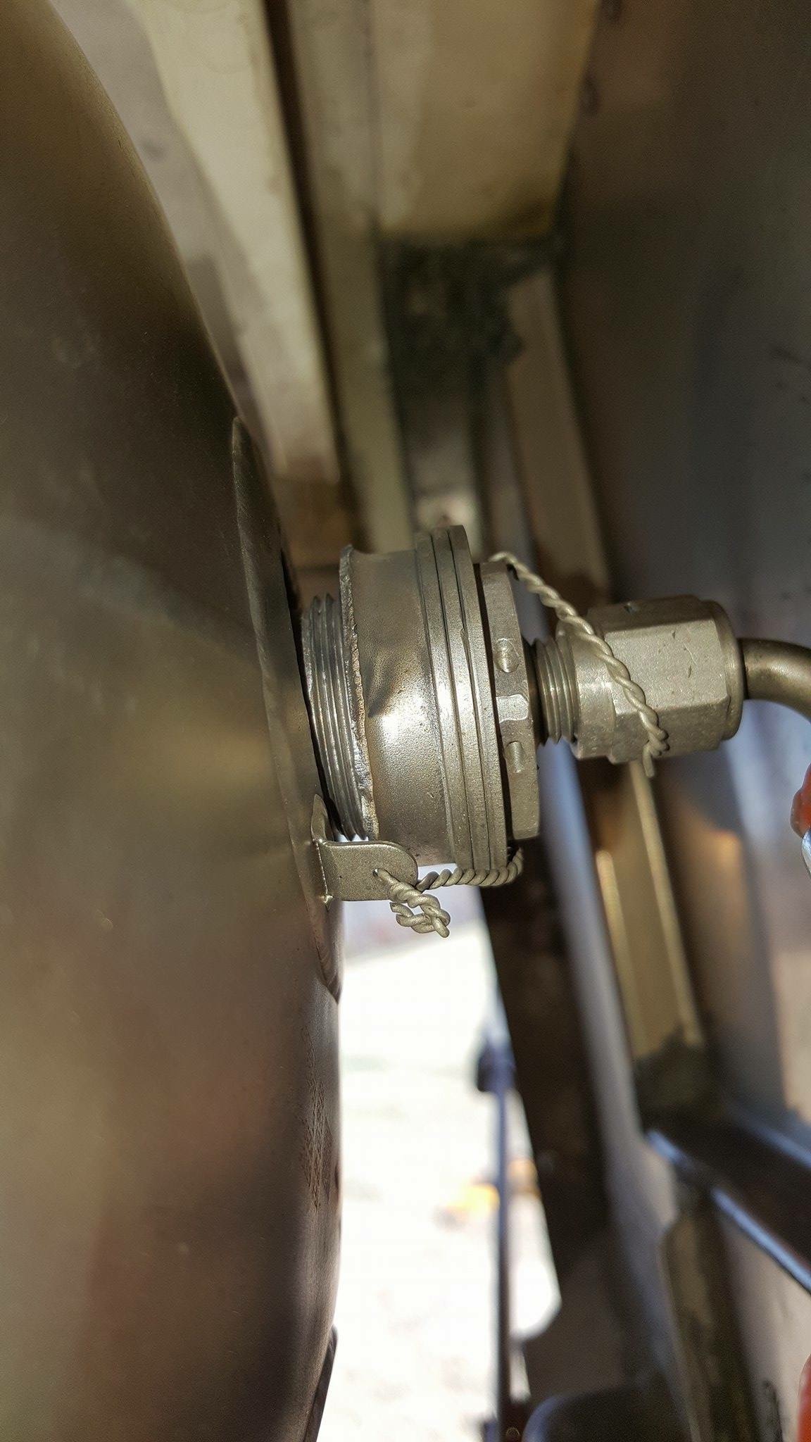
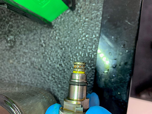
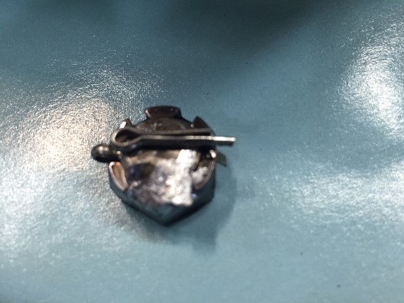
Fuel nozzle boss separated from the engine outer combustion case.
Austro Engine
E4-A - Engine Failure Due To Foreign Object Debris
SDR #20170106003
Subject:
While cruising/descending at 9000 feet, the pilot observed dropping oil pressure and increasing oil temperature. Failure code warnings were also observed. The pilot landed the aircraft, which sustained some minor damage. The lower cowl and underside of the aircraft were contaminated with engine oil.
Transport Canada Comments:
An engine investigation revealed that a foreign object had entered one of the cylinders and damaged the piston. This resulted in the piston cracking and allowing combustion gasses to pressurize the crankcase thereby forcing out the engine oil.
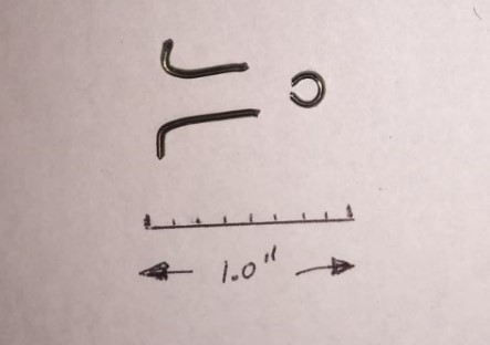
The source of the foreign object was not known however the evidence left behind on the piston indicated that it may have been caused by a piece of lockwire.
It is important for Aircraft Maintenance Engineers to be certain that the areas surrounding critical areas be cleaned of any foreign materials following maintenance activities.
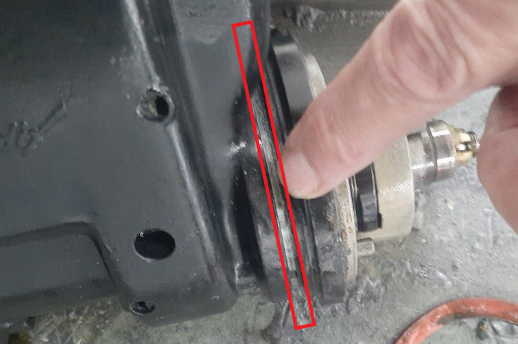
Piston with evidence of foreign object debris damage
AVCO Lycoming
O-320-H2AD - Rocker Arm Failure
SDR #: 20210707007
Subject:
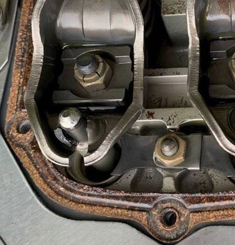
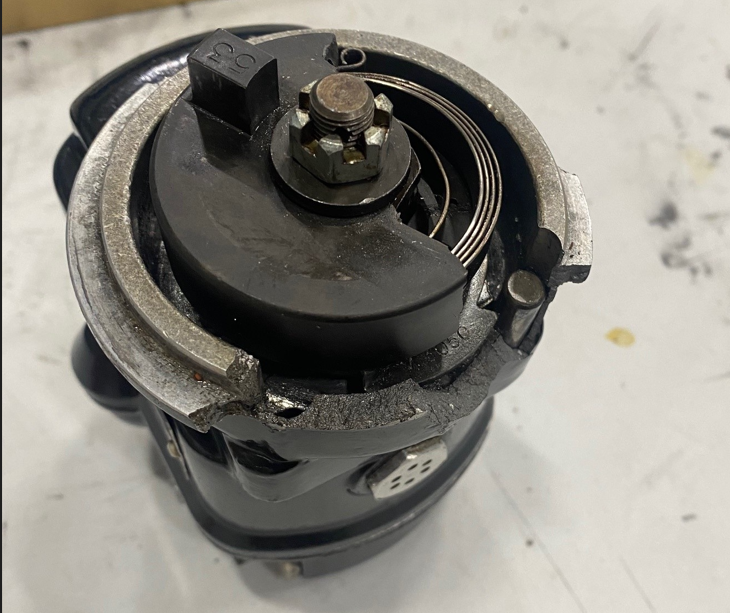
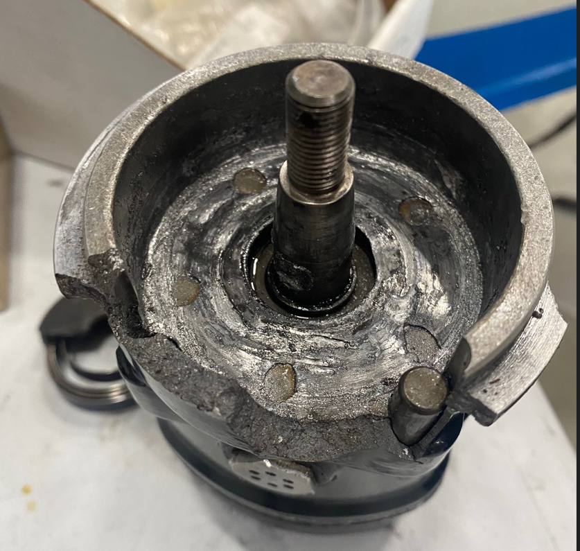
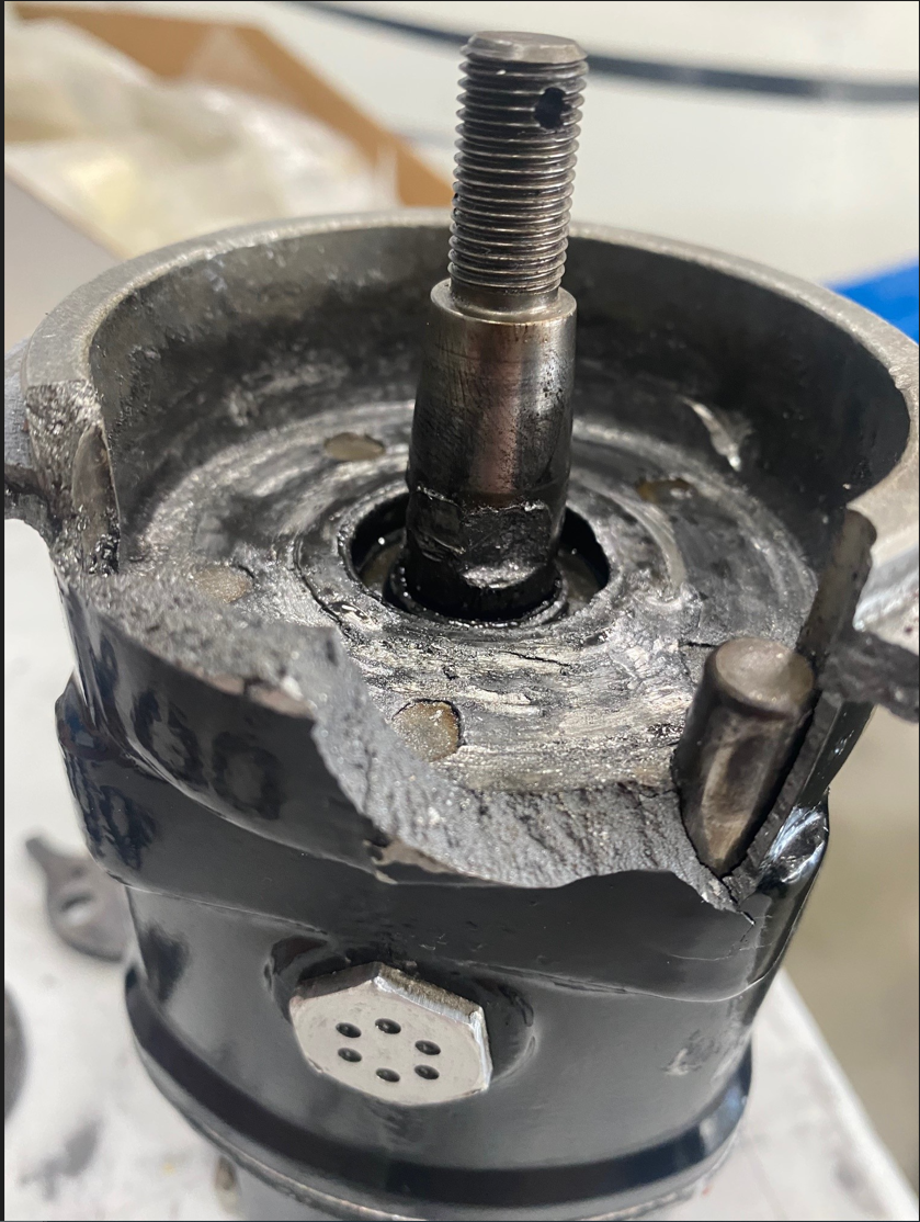
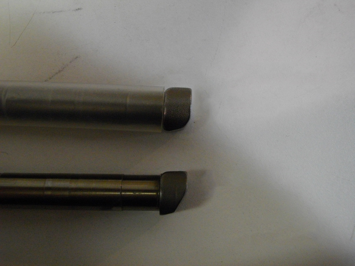
A student pilot was on a solo flight when they experienced a sudden loss of power and a rough running engine. Troubleshooting and attempting to resolve the issue was unsuccessful and the pilot was unable to maintain altitude. As such, the pilot landed the aircraft in a nearby field. They activated the ELT and completed a mayday call before touching down. Upon initial inspection there was no damage to the aircraft from the landing. The mechanical issue was quickly found to be on the cylinder #4. The intake push rod tube was bent, and the exhaust push rod broke through the rocker arm. There were approximately 240 hours on this engine since overhaul with no significant maintenance (besides required inspections) completed prior to the failure. Cylinders were new at overhaul.
Transport Canada Comments:
After conducting an investigation, it was found that Lycoming Mandatory Service Bulletin (MSB) 639 had not been performed at the recommended 50-hour interval following rocker arm replacement during overhaul. To prevent further incidents, Transport Canada Civil Aviation suggests that owners, operators, and maintainers incorporate MSB 639 and continue to file Service Difficulty Reports (SDRs) in the event of rocker arm defects.
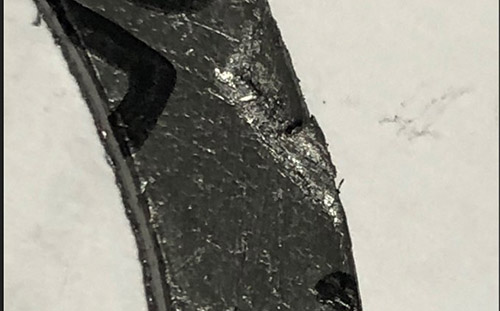
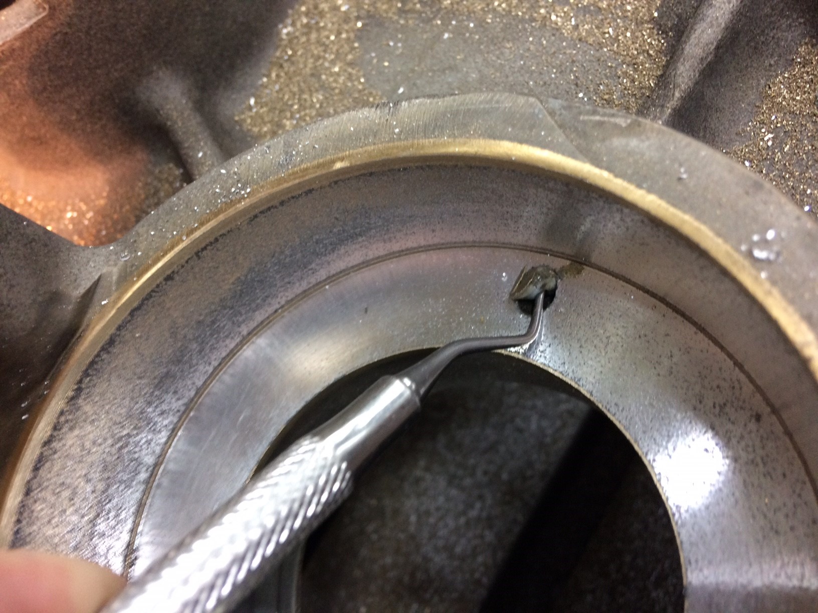
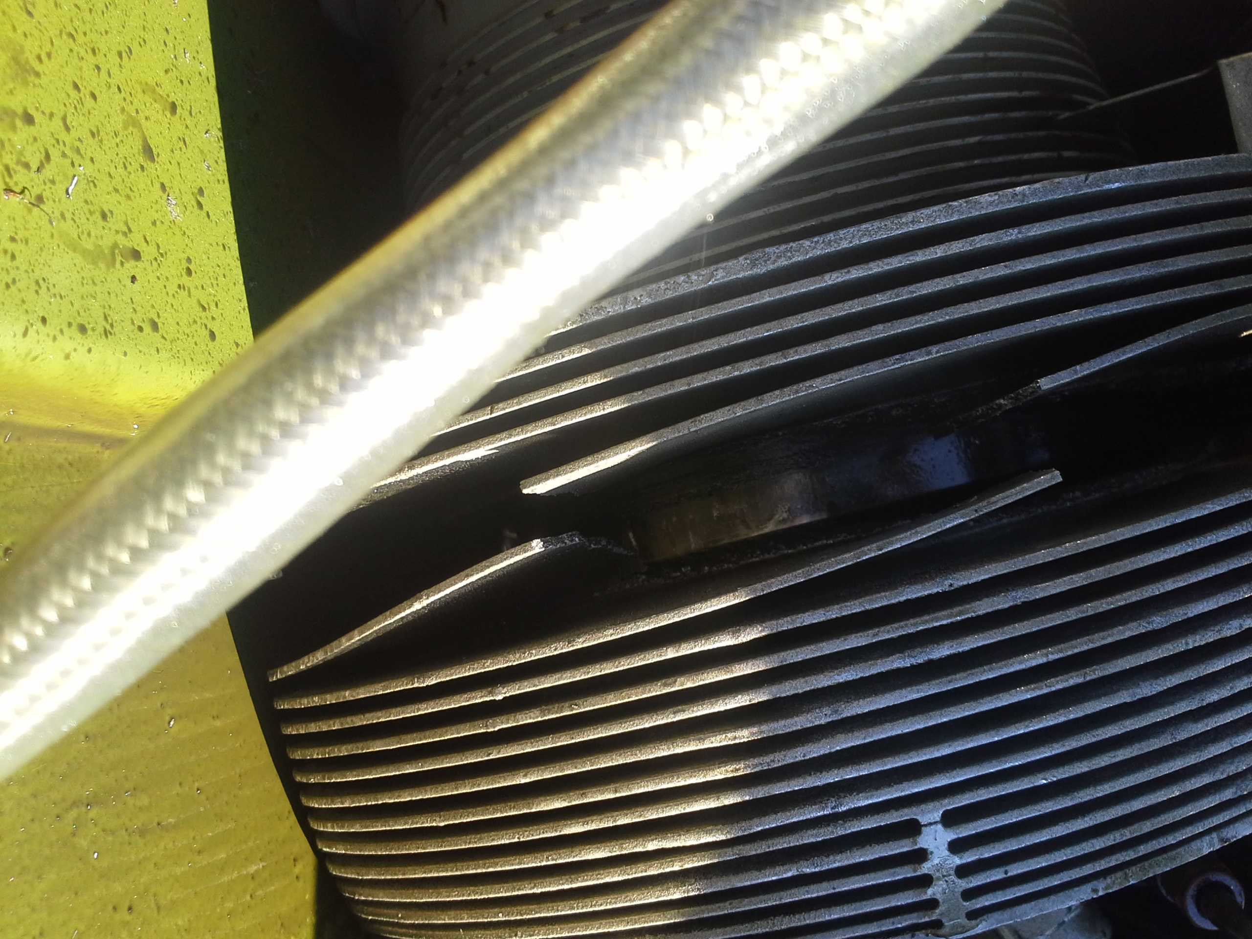
Picture 1 – Rocker Arm failure at pushrod socket
O-320-H2AD - MA-3 and MA-4 Series Carburetor – Liberated Accelerator Pump Discharge Tube
SDR #: 20210923020
Subject:
While landing, the student and flight instructor noticed that they were unable to reduce the engine speed to idle, revolutions per minute (RPM) could only be controlled between 2000-2200 RPM. They declared an emergency, shut down the engine in short final and landed safely. The company’s maintenance technicians inspected the engine throttle control and noticed that it could not be pulled back. The carburetor was removed, and it was found that the accelerator pump discharge tube had detached and stuck in the butterfly.
Transport Canada Comments:
The MA-3 and MA-4 series are updraft style carburetors found on Lycoming, Continental, and other normally aspirated engines. They are currently manufactured by Mavel-Schebler Aircraft Carburetors (MSA) and were previously manufactured by Precision, Facet, and Volare.
The accelerator pump discharges fuel only when the throttle fly is moved toward the open position. In MA4-5, MA-5 and MA-6 series carburetors, this additional fuel is fed through the main discharge nozzle, and in smaller carburetors such as the MA-3 and MA-4 series, a separate discharge tube is utilized. This discharge tube is bonded in the sidewall below the venturi and main discharge nozzle.
Possible indications of a liberated discharge nozzle could include:
- Obstructed throttle fly, jammed throttle control
- Fuel found in airbox
- Cylinder Foreign Object Damage (FOD)
- Failure to start
- Sluggish acceleration during takeoff or other phases of flight
Accelerator pump discharge tubes are bonded in place during assembly or overhaul and undergo a specified torque check to determine serviceability. Transport Canada Civil Aviation (TCCA) recommends that a detailed visual inspection of this area be performed whenever possible to detect a disbonded accelerator pump discharge tube and that such defects continue to be reported by submitting a Service Difficulty Report (SDR).
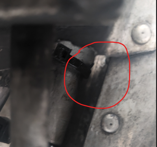
Picture 1 – Discharge tube lodged beside throttle fly
Picture 2 – Discharge tube
Picture 3 – Left-hand (L/H) unserviceable carburetor without discharge tube, right-hand (R/H) serviceable carburetor with discharge tube bonded in place
IO-540-K1B5 - Continental Aerospace Technologies (Bendix / TCM) S-1200 Series Magneto Mounting Flange Loose
SDR #: 20210326007
Subject:
After flight, oil was observed to be leaking from the left engine. The Aircraft Maintenance Engineer who inspected the engine found the magneto to still be firmly fastened to the engine, but its case had split at a swaged joint, allowing oil to leak from the resultant gap.
Transport Canada Comments:
It was confirmed that all 3 internal wrenching screws part number (P/N) 10-349652, which secure the flange to the body of the magneto, were found loose. S-1200 series magnetos, which include 4, 6 and 8 cylinder models all use this method of attaching the flange to the body of the magneto.
Possible scenarios involving loose or fully migrated P/N 10-349652 screws include: oil leak, metal contamination of engine oil system or magneto failure.
Service Difficulty Report (SDR) data indicates this event is not a trending defect, the majority of related occurrences were prior to 1997. The inclusion of the following information in the S-1200 Series Service Support Manual may have played a role in mitigating a continuing airworthiness concern.
Multiple notes and warnings are included in the published service manual, stating to remove and discard the flange securing screws and washers, regardless of whether disassembly is for the purpose of inspection, parts replacement, or overhaul. Additionally, adherence to published fastener torque specifications is highlighted.
A daily pre-flight check may not specifically include checking for security of attachment of the magneto, although including such an item may be beneficial.
IO-540-K1G5D - Filter Collapse-Pressure Failure
SDR #: 20210420010
Subject:
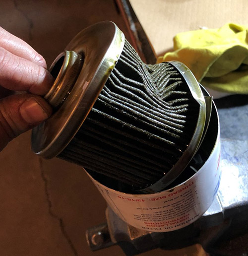
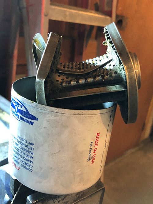
The oil filter was removed and cut open for inspection during the annual inspection of the aircraft. After cutting open the filter, it was discovered that the centre tube and media were crushed with no signs of damage to the oil filter can. The oil filter was in service for 46.5 hours at the time of the discovery.
Transport Canada Comments:
The oil filter in this occurrence has experienced a filter collapse-pressure failure. This is most likely due to excessive pressure buildup during a cold start. Unfortunately, as the filter manufacturer suggests “…after the element is crushed, you’ll have little or no oil filtration. You won’t find the crushed element until the next oil change, as oil pressure will appear normal on the engine oil pressure gauge.”
Identifying signs of a filter collapse-pressure failure may be difficult, a domed filter top, an oil leak or a high revolutions per minute (RPM) during a cold start may indicate that the filter has experienced an over-pressurization. Transport Canada, Civil Aviation (TCCA) suggests that owners, operators and maintainers pay close attention and identify the root cause when defects such as these arise.
For additional information on this subject published by the oil filter manufacturer, please refer to Tempest Tech-Tip 0613 – Alaska Cold Starts
Picture 1 – Filter collapse-pressure Failure
Picture 2 – Centre tube collapse
O-320-E2D - Champion Aerospace Slick Magneto Loose or Broken Impulse Coupling Rivets
SDR #: 20180925011
Subject:
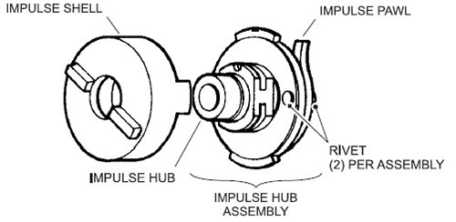
During the first 500 hour inspection on the magneto, the rivets on the impulse coupling were found to be loose. The manufacturer was contacted and the impulse coupling was replaced.
Transport Canada Comments:
Champion Aerospace has published Service Bulletin (SB) SB2-19A Mandatory inspection of impulse coupled Slick by Champion magnetos. Engines utilizing Slick 4200, 4300, 4700, 6200, 6300 and 6700 series magnetos, which have had the impulse coupling replaced with a kit dated 26 February 2015 through to 1 February 2019 are affected. Background information in the SB notes: A loose or broken rivet could potentially enter the gear train of the engine resulting in damage to the gear train or damage to engine accessories and could possibly cause catastrophic engine failure.
Transport Canada, Civil Aviation (TCCA) encourages all owners and operators to review the contents of this SB and continue to report service difficulties for any loose rivets found.
Impulse Coupling
IO-540-K1B5 - Connecting Rod Bushing Failure
SDR #20170404111
Subject:
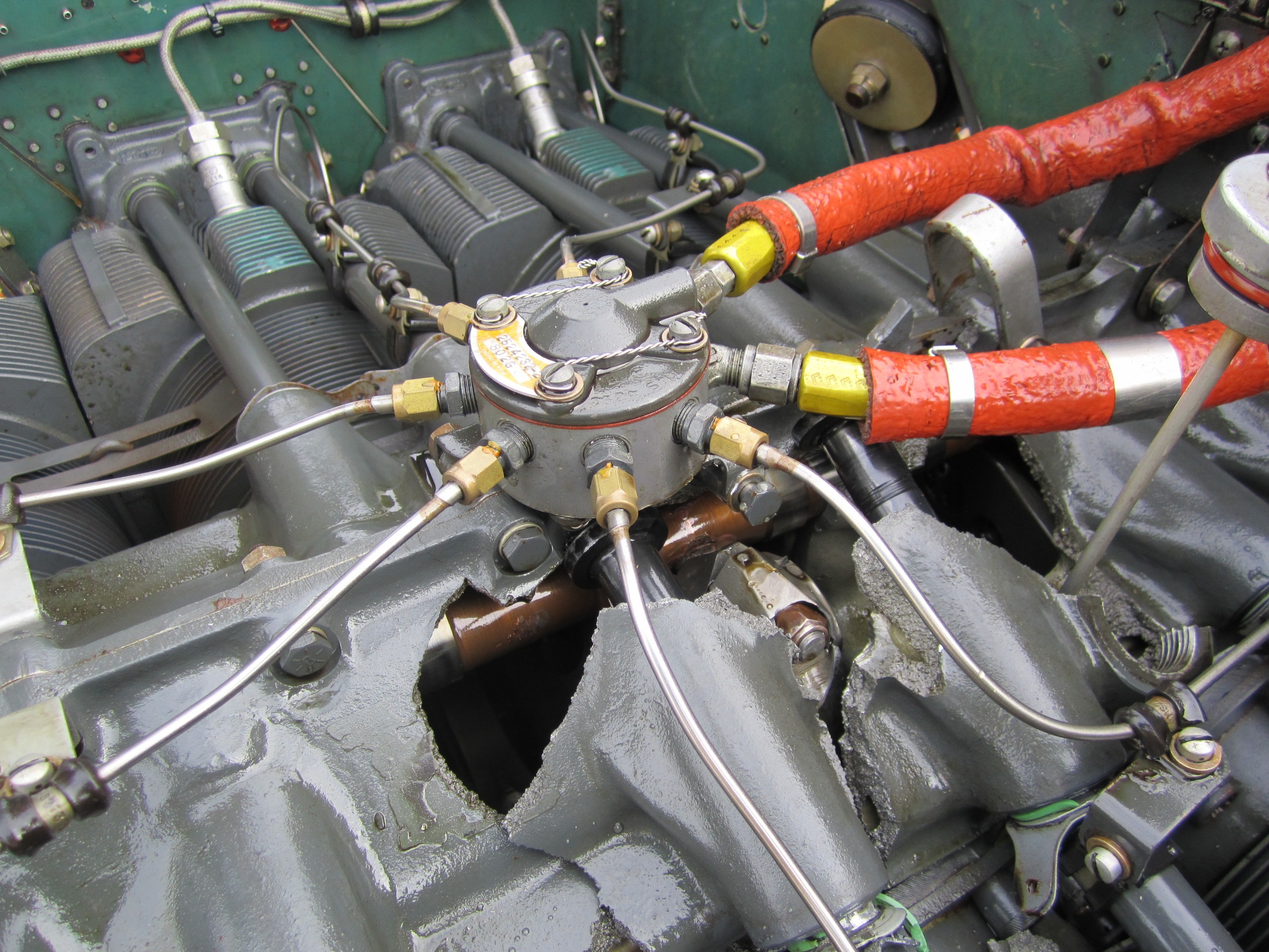
During climb to altitude, the left hand engine sputtered and shutdown. The aircraft returned for landing without further incident. A visual inspection conducted by the pilot revealed a catastrophic failure in the top of the crankcase.
Transport Canada Comments:
The manufacturer, Lycoming, has issued Mandatory Service Bulletin 632B to identify and remove from service certain connecting rods with non-conforming small end bushings. The Federal Aviation Administration (FAA) has issued Airworthiness Directive 2017-16-11 to mandate the inspections and actions listed in the Lycoming Service Bulletin. Transport Canada urges the report of any related service difficulties found on engines not listed in the models affected section of Mandatory Service Bulletin 632B.
Hole in crankcase can be seen following a connecting rod bushing failure.
CFM International
CFM56-7B26/E - Improper Magnetic Chip Detector (MCD) Installation
SDR #: 20230223003
Subject:
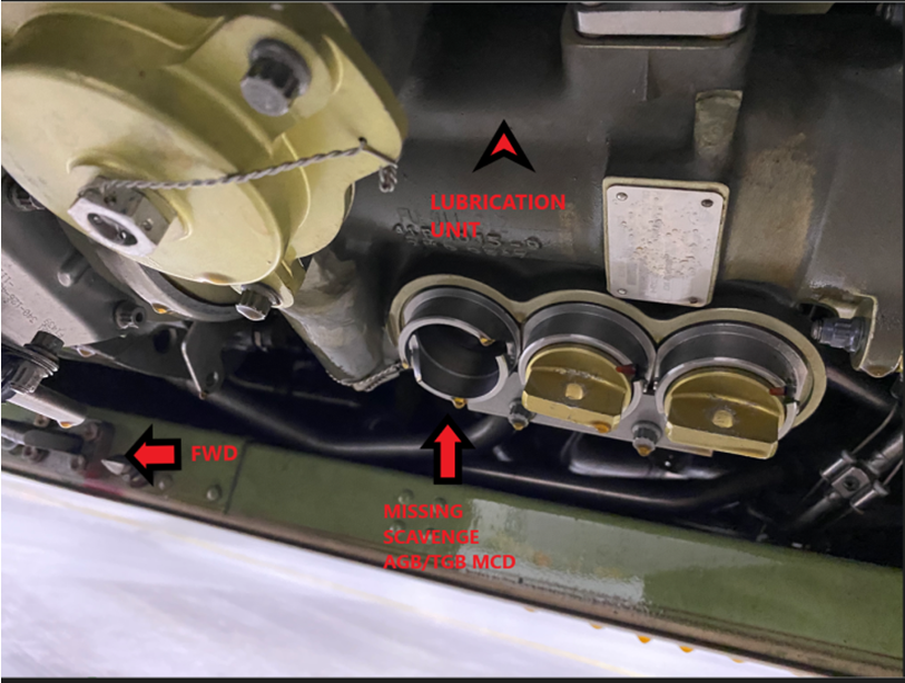
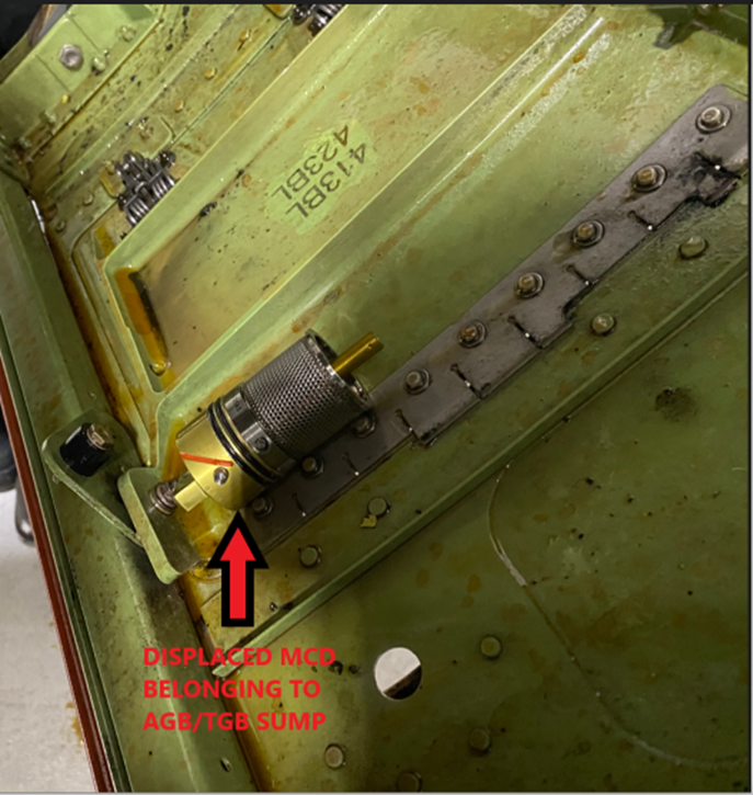
During cruise, on engine number two, low oil quantity was indicated. The quantity soon decreased and an air turnback was initiated. During the turnback, the oil pressure began to fluctuate, exhaust gas temperature and oil temperature began to rise higher than engine number one. Oil pressure fluctuations became more rapid with the indication turning amber, then red. The decision was made to shut down engine number two. The aircraft landed without further incident and towed to the hangar. Maintenance personnel opened the number two engine cowlings and found that an MCD was not in the lubrication unit but was resting on the inside of the cowling. The remaining two MCDs were checked and found secure. All three MCDs on number one engine were checked for correct installation and it was found that the accessory gearbox (AGB) MCD was not locked in the proper detent position. On 13 January 2023, a detailed visual inspection of each engine forward sump, aft sump, and AGB MCDs was carried out as per maintenance task card and installed as per aircraft maintenance manual. The probable cause of the MCD backing out of the lubrication unit was a failure to lock the MCD into position where the bayonet pins fully engage in the slots. It is believed that during the flight of 27 January 2023, the number two engine MCD displaced to the point where the internal cowling structure held it in a position where it still engaged the check valve, allowing the oil to flow out. What contributed to the installation error was the fact that the aircraft maintenance engineer who was performing the task did not use the specified tool as per the maintenance manual.
Transport Canada Comments:
In this event, the published instructions for continued airworthiness (ICAs), specified the use of a special tool for installing the MCDs. The operator suggests that the lack of special tool use contributed to the MCD not being secure and backing out enough to still engage the shut off valve and resulting in oil loss.
It is difficult to speculate why the maintainer did not use the tool to secure the MCDs. Time constraints and pressure to finish the inspection tasks or even tool availability may have been factors.
Transport Canada would like to remind operators and maintainers to follow manufacturers ICAs when accomplishing any task, no matter how straight forward the task may seem. In this event luckily the number one engine MCD, which was found not secure, remained in place and the aircraft landed uneventfully with one engine.
Picture 1 - Lubrication Unit
Text in the picture: Lubrication Unit, FWD, Missing Scavenge AGB/TGB MCD
Picture 2 - MCD
Text in the picture: Displaced MCD Belonging to AGB/TGB Sump
CFM56-5B3/P - Ruptured Fuel Line
SDR #: 20230104008
Subject:
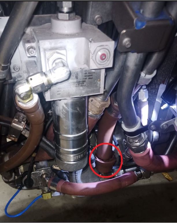
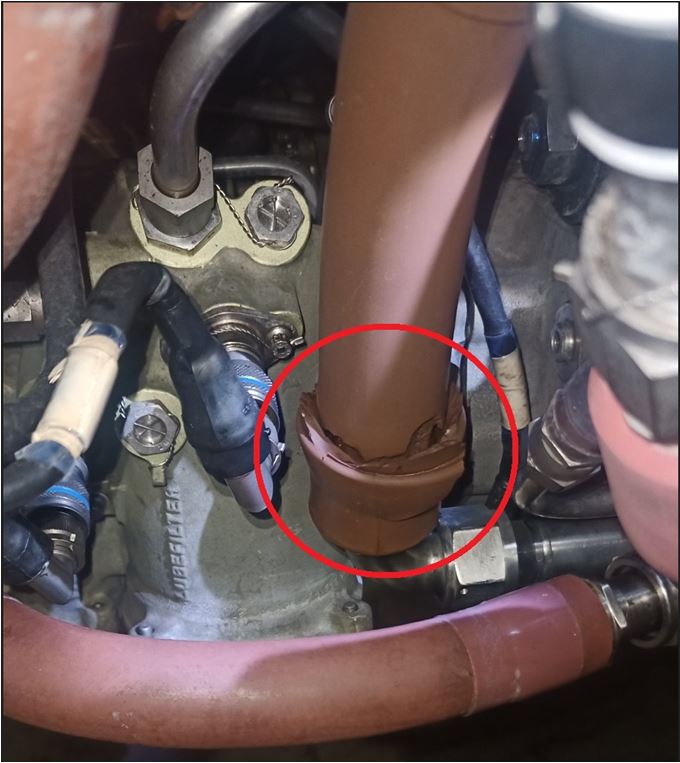
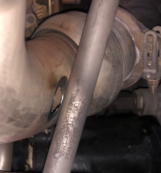
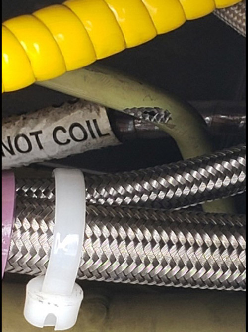
Dripping fuel from right-hand engine fan cowl was found on a walk around. Further inspection of the area showed a ruptured integrated drive generator (IDG) heat exchanger fuel line. The fuel oil heat exchanger tube/line was replaced.
Transport Canada Comments:
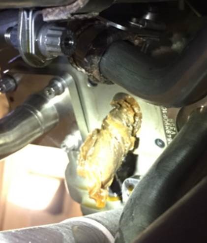
Transport Canada Civil Aviation (TCCA) would like to make operators and maintainers of this engine and similar engine models aware of this event and to pay particular attention to this line when accessing or inspecting this area.
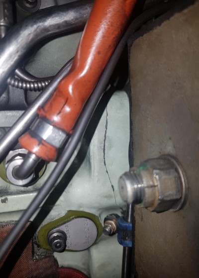
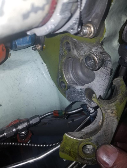
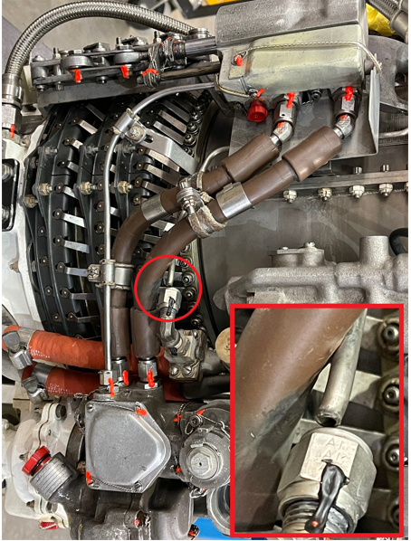
The root cause of the ruptured fuel line is still under investigation, however, as seen in the photos, the congestion of lines and hoses and the protective coating on the ruptured line would have made detection of a fuel leak very challenging at best. Luckily, a fuel leak was noticed during a walk around, the ensuing maintenance inspection located the event line, and a possible serious situation was avoided.
Please report any findings similar to this event to TCCA through the Web Service Difficulty Reporting System.
Photo 1: Fuel line location
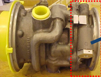
Photo 2: Ruptured fuel line
CFM56-7B26/E - Loss Of Oil Pressure Event
SDR #20170217010
Subject:
On taxi out, the crew reported a low oil pressure warning for engine number one. The crew shut down the engine and returned to the gate.
The subject engine is being replaced. Maintenance found oil quantity zero, the tank was empty and oil was draining from the forward sump drain port.
Transport Canada Comments:
Investigation revealed foreign material in the tube of the scavenge pump. Analysis revealed the material to be a paper towel. It is not known when this foreign material was introduced to the oil system.
This event was clearly a human factors issue. Transport Canada Civil Aviation (TCCA) continues to see these events occur (see feedback magazine past issues 1/2013: improper use of tooling causing in flight shutdown, 3/2014: oil filler cap left off and 4/2014: improper fuel shipping cap.)
Human factors related events like these continue to be difficult to eliminate, this is in part due to the fact that the aviation industry still relies very heavily on the professionalism and competence of front line individuals to detect and avoid these types of errors and doesn’t necessarily go the extra step to consider the associated organizational factors that may have contributed.
Implementing a formal Safety Management System (SMS) is a good place to start in order to understand organizational factors and their influence on safety. TCCA along with other Civil Aviation Authorities have worked to publish various online tools to aid the aviation industry in these areas. Some examples are:
- TCCA’s Easy Reference Guide of Safety Management System-related Documents
- Safety Management International Collaboration Group (SM ICG)
- Maintenance Workload
- Safety Culture
Although front line staff (ground handlers, Aircraft Maintenance Engineers [AME] and Pilots) can be considered the last line of defense to prevent these types of incidents, organizations should not rely on them to be the only line of defense. TCCA encourages aviation organizations to take the steps necessary to gain an understanding of the organizational factors that exist within their businesses so that they can better understand their influence on the safety outcomes of their operations.
Engine case with oil tube removed revealing paper towel stuck in port
Garrett
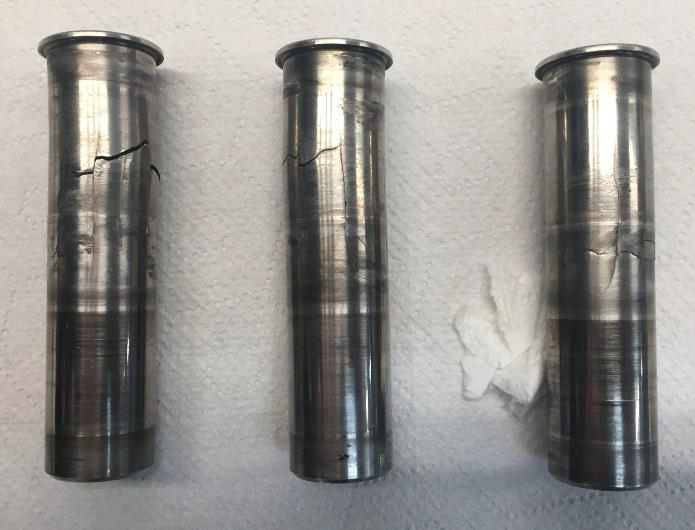
TPE331-12UHR-702H - Cracked Tachometer Generator Drive Adapter Inserts
SDR #: 20200911024
Subject:
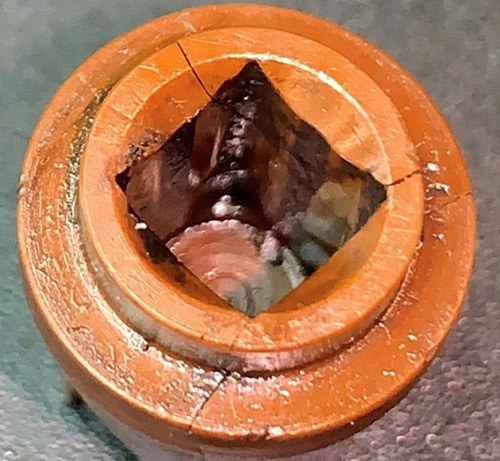
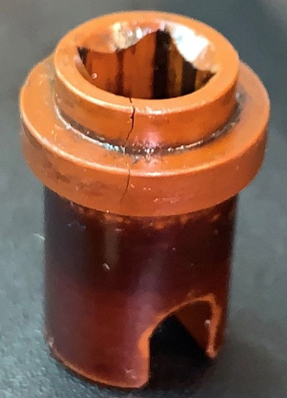
Upon inspection of an engine for a gearbox repair, it was noted that the adapter insert for the tachometer generator drive was cracked in multiple places.
Transport Canada Comments:
These tachometer generator drive adapter inserts are a common component on numerous engine makes and models. They mate the tachometer generator drive to the engine or gearbox to translate rotating movement into a percentage or rpm displayed on a cockpit instrument.
These inserts are often overlooked due to their location and low failure rate. In this event, the insert was cracked but continued to connect the tachometer generator drive to the accessory gearbox.
Due to the diligence and professionalism of maintenance personnel during the gearbox repair, the cracked insert was discovered and a possible event was averted. Well done to these maintainers for the effort to ensure they were releasing a serviceable product back to the customer.
Picture 1 – Cracked adapter insert top view
Picture 2 – Cracked adapter insert side view
TPE331-11U-612 - Damaged Gasket
SDR #: 20201103021
Subject:
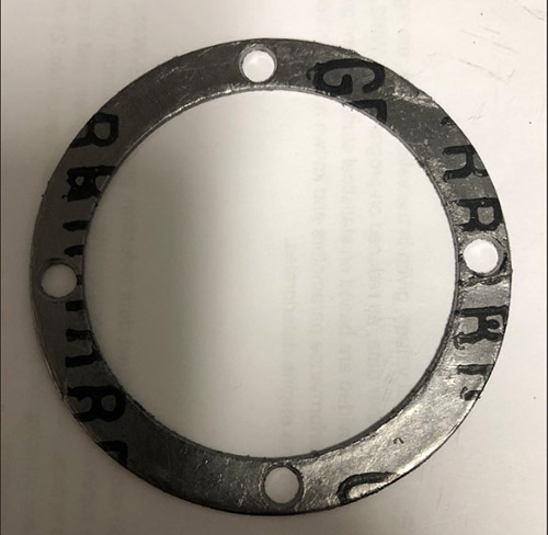
While carrying out a repair on a Garrett engine, we went to get a new gasket to seal the aft turbine oil area. When the gasket was taken out of a new package, it was noted that the gasket was not manufactured properly, it had damage on one of the surfaces. We used another gasket from stores and it was serviceable.
Transport Canada Comments:
Certain tasks such as replacing gaskets, O rings or seals are often considered menial. Inattention to manufacturer’s instructions or standard practices when installing these components, may result in leaks that could have a detrimental result if a fuel leak ignited, or an engine shut down due to lack of lubrication or fuel starvation.
Maintainers are reminded to follow published instructions and verify the condition of these components prior to installing them. Many O rings, for example, have an expiry date or shelf life stated on the packaging, and do not assume a new part is a serviceable part.
In this case, due to this operator’s attention to detail and verification of the condition of this gasket prior to the installation, a potential oil leak was averted.
Transport Canada Civil Aviation (TCCA) requests that owners and maintainers continue to submit Service Difficulty Reports (SDRs) when defective parts, such as this gasket, are discovered.
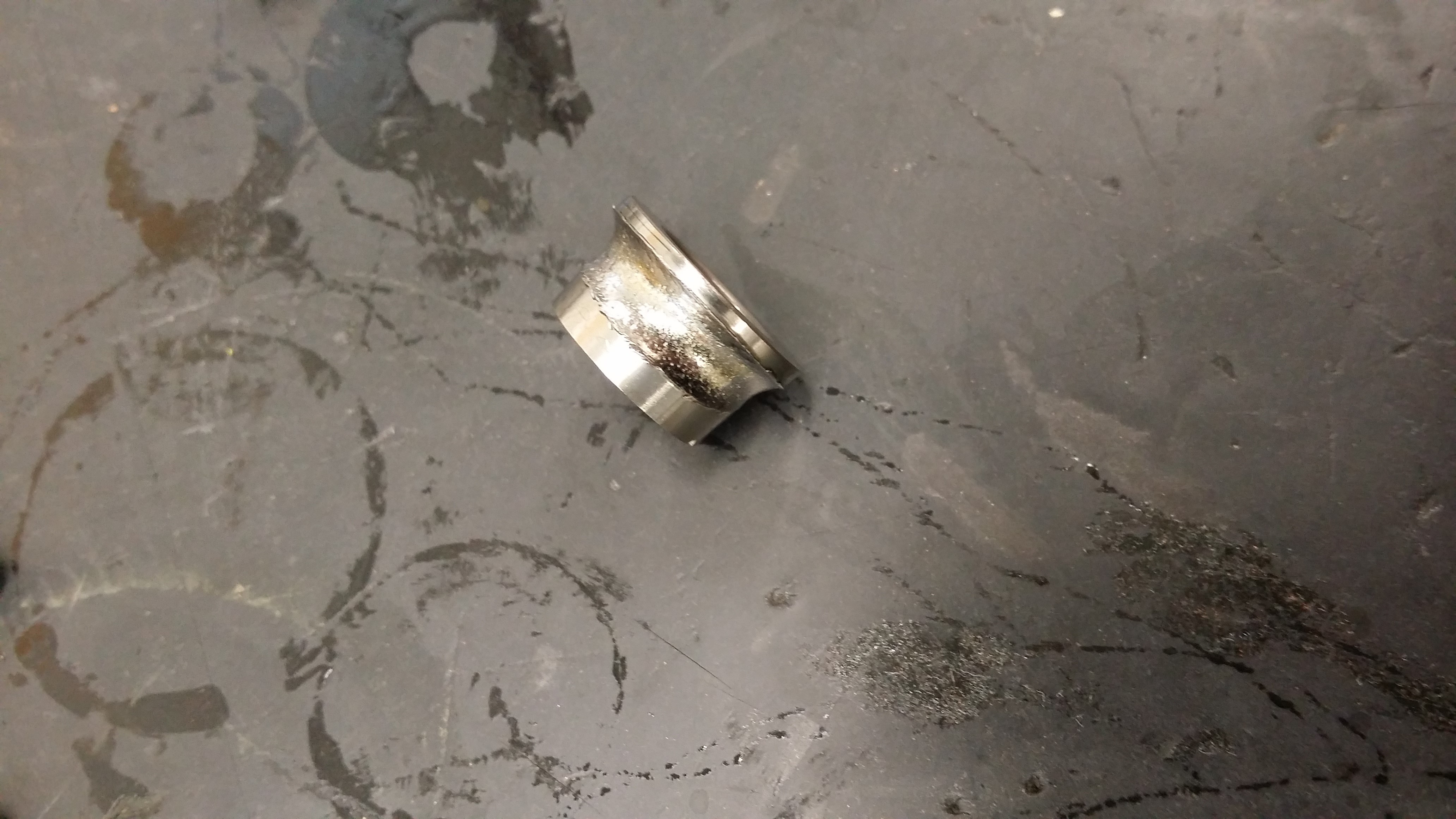
Picture 1 – Damaged gasket
Picture 2 – Close-up of damaged area of gasket
TPE331-11U-612G - Cracked Engine Mount
SDR #: 20200730008
Subject:
During a routine phase 6 inspection of the engine, the magnesium engine case of the #2 engine at the outboard engine to truss mounting pad was found cracked. After removal of the engine for repair, that portion of the case detached. Review of the history found no recent events or defects that could have caused the failure. In February 2016, the engine had been removed and sent to an approved engine repair facility due to a level 2 propeller strike, this was 2640 hours prior to this failure. The engine had also been removed for a hot section inspection/compressor refurbishment, 1421 hours prior to this failure. No defects in the failure area were found during those major shop visits.
Transport Canada Comments:
Magnesium castings are lightweight and strong, however they are susceptible to cracking due to thermal cycling during manufacture, fatigue failure from vibration, human factors if studs or bolts are over torqued, and corrosion if protective coatings wear or are not properly applied.
In this event, a meticulous inspection detected this failure preventing what may have been a serious incident or accident should the mount have failed altogether.
Transport Canada would like to highlight this event and recommend that maintainers and owners pay particular attention to this area during inspections. Transport Canada Civil Aviation (TCCA) commends the work of these maintainers for their thorough maintenance practices.
Picture 1 – Cracked engine mount
Picture 2 – Detached part of casting
TPE331-12UHR - Idler Gear Bearing Failure
SDR #: 20200908013
Subject:
An engine spectrometric oil analysis program (SOAP) sample result indicated that a bearing was failing. The oil sampling facility lab called to let us know of the sample results. The engine was forwarded to the turbine shop for repair and it was noted that when the gearbox was removed, the idler gear duplex bearing had failed.
Transport Canada Comments:
Oil analysis is an effective tool that can be used by operators and maintainers to monitor the condition of an engine. It assists in the early detection of issues that a minor repair may rectify before costly components are damaged or a major engine failure occurs.
As seen in this event, oil analysis detected deterioration of the idler bearing before a catastrophic failure occurred and may have prevented an expensive repair or a serious incident from an engine shutdown.
Although oil analysis is effective at detecting accelerated wear of internal components over time, it has limited effectiveness in predicting a sudden break or fracture.
Transport Canada encourages the use of these programs by all owners and operators to enhance flight safety through the early detection of failing components.
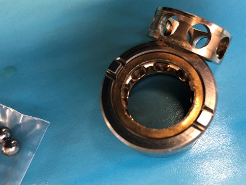
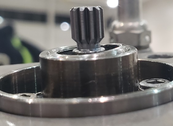
Idler gear bearing
TPE331-10UA-511G - Engine SOAP (spectrometric oil analysis program) Sample - A Proven Maintenance Tool
SDR #20160926005
Subject:
The pilots reported that a chip light on the aircraft had illuminated during climb for 2 minutes and then went out. Maintenance was advised of the indication when the aircraft returned to base. The chip detector was inspected and a SOAP sample was taken. The sample was rushed out to a lab for inspection and the results revealed that an engine inspection was required immediately. The engine was removed from the aircraft and forwarded to the turbine shop. The gearbox was disassembled and the torque sensor idler bearing was found to have failed.
Transport Canada Comments:
This report proves the effectiveness of good preventative maintenance and how an oil analysis program can help increase safety by preventing possible in flight emergencies and reduce operating cost by catching problems before they become catastrophic.
Idler bearing race showing significant wear
TPE331-10 - Incorrectly Set Turbine Rotor Rivets
SDR #20170113010
Subject:
After routine maintenance at an outside repair station, the propeller was turned to prepare for propeller removal. It was observed that the engine would only rotate slightly due to part of the rotating group getting caught on something internally.
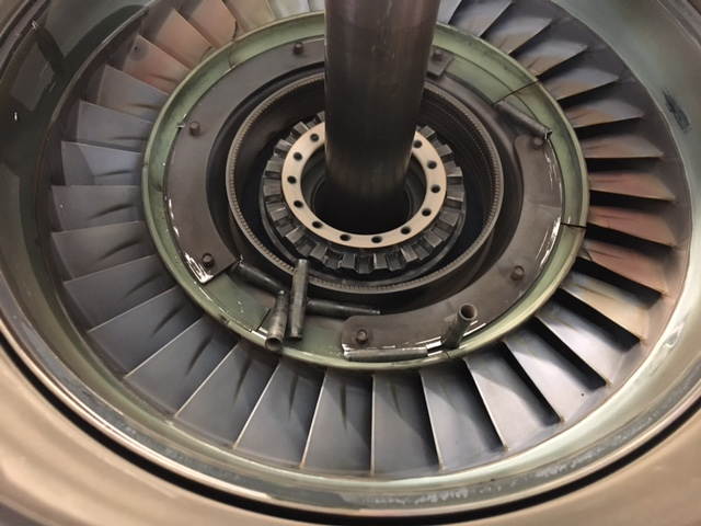
The engine was inspected and it was found that some of the retaining pins (rivets) holding the blades of the second stage turbine (Part Number 3102106-10) had fallen out. After some research it was noted that the rivets were out of dimensions per Honeywell manuals.
The engine is being inspected at an approved overhaul facility and the second stage turbine is in the process of being replaced.
Transport Canada Comments:
Attention to detail is of paramount importance when conducting complex maintenance tasks such as engine assembly. Manufacturers’ recommendations must be followed (CAR 571 Standard 571.02). This is particularly important when the final assembly is hidden from view and not easily inspected.
Fortunately this resulted in a ground incident rather than an inflight emergency.
Rotor assembly with rivets that had fallen out due to incomplete setting
General Electric
CT58-140-2 - Broken P3 Air Line
SDR #: 20210817009
Subject:
During forestry fire-fighting operations, after the load of water was picked-up and the climb was initiated, Engine Number 2 was not providing the required power. When compared with Engine Number 1, the torque was 40% lower and the T5 was 120 to 130 degrees Celsius below the Engine Number 1 T5 indication. The water load was released, the checklist for the low side governor failure was completed, and the helicopter returned safely to the base. An engine inspection revealed a broken P3 air line.
Transport Canada Comments:
The root cause of the broken air line has yet to be determined, however, fatigue and stress may have played a role in this failure. The photo shows the broken air line offset from the B nut, which may suggest a side load from installation.
Due to congestion of lines and bundles on many engines, it is sometimes difficult to have proper alignment when connecting fluid lines. A slight bend of a line to achieve contact, may induce stress and lead to a failure. Another common error is securing and torquing one end of the line before connecting the other end, instead of connecting both ends and then securing and torquing.
Transport Canada Civil Aviation (TCCA) would like to make operators and maintainers of this model and similar models aware of this event. It is also recommended that close attention be paid to this line when inspecting in this area.
Broken P3 air line
CF34-3B1 - Engine Main Fuel Pump
SDR #: 20220124011
Subject:
During a routine inspection, fuel was discovered in the lower engine cowl. Upon further investigation, it was discovered that the engine-driven fuel pump had developed a small pinhole in the inlet case allowing boost pump pressure to leak from the pump body. The affected pump was replaced, and the aircraft returned to service.
Transport Canada Comments:
We have received several Service Difficulty Reports (SDRs) related to fuel leaks from a pinhole on this particular fuel pump part number. The leakage is attributed to a pinhole on the relief valve wall of the secondary housing as a result of erosion caused by the effect of cavitation over the relief valve cavity threads. These leaks may be barely detectable due to the size of the pinhole.
General Electric added inspection instructions in the component maintenance manual to check for cavitation on the secondary housing and issued Service Bulletin (SB) 73-0050 R00 identifying new spare parts for a redesigned main fuel pump with rerouted passageways.
Transport Canada Civil Aviation (TCCA) would like to make operators and maintainers of similar models aware of these events, and urges everyone to be vigilant while inspecting the fuel pump area for leaks.
Photo 1 – Main fuel pump secondary housing
Photo 2 – Pinhole at secondary housing
CF6-80C2B6 - Main Engine Control Driveshaft Migration
SDR #: 20201111012
Subject:
During the left engine start, a hung start condition was observed, with the power turbine speed N2 at 75% and 450 degrees Celsius Exhaust Gas Temperature (EGT), with no response to throttle movement. The engine was shut down for maintenance troubleshooting. Troubleshooting was carried out and identified the Main Engine Control (MEC) as being at fault. Upon maintenance removing the MEC from the accessory gearbox, the driveshaft was found no longer mated to the MEC. The driveshaft had migrated towards the gearbox and was no longer rotating the MEC internal shaft. The nut, attaching the driveshaft within the MEC, had backed off to allow this migration of the shaft. The MEC was replaced, and the aircraft was returned to service.
Transport Canada Comments:
From viewing the MEC driveshaft threads photograph, it appears that the threads were worn or damaged. This condition may have been a factor contributing to the attaching nut backing off. The use of wrong hardware, cross threading or over torque of the securing nut, and thread strength, are a few possible causes of thread damage. Until an investigation is carried out, the root cause of this event remains undetermined.
Although the investigation is still ongoing, Transport Canada Civil Aviation (TCCA) would like to bring this event to the attention of maintainers and operators of the CF6-80C2B6 model or similar models. A verification of the MEC driveshaft condition and security when in this area, or before installation of the MEC, may prevent a similar or more serious incident.
Photo 1 – MEC driveshaft
Photo 2 – MEC
CF34-8E5 - Cracked Fuel Pump Adapter
SDR #: 20200211018
Subject:
During a post engine installation leak check ground run, fuel was noted to be leaking from the number one (1) (left-hand) engine fuel pump. The subsequent investigation found an adapter, which attaches to the fuel pump, to be cracked, which allowed fuel to escape. The adapter was replaced and the engine was returned to service.
Transport Canada Comments:
Post-maintenance functionals, leak checks, ground runs etc. are vital parts of maintenance procedures in the Instructions for Continued Airworthiness. All personnel must be thorough when performing such checks to ensure service difficulties like this one are discovered and rectified before the aircraft is released to service. “Well done” to these diligent maintainers for catching this service difficulty which may have had a potential disastrous outcome if not detected.
Fuel pump adapter with indicated crack area
CF34-8C5 - Chafed Fuel Line
SDR #: 20200603001
Subject:
A fuel smell was present in the cabin during various phases of flight. An investigation found that the 6th stage duct was cracked, making it possible for the fuel line and the duct to rub together. Chafing caused perforation in the fuel line. The right-hand engine will be changed.
Transport Canada Comments:
Performing inspections and maintenance tasks in many sections of an aircraft can be challenging. The routing of lines, wire bundles and hoses in confined spaces makes it difficult to spot every area that may have rubbing or chafing.
Maintainers must be thorough when inspecting or performing tasks in these areas. Always follow the manufacturer’s Instructions for Continued Airworthiness (ICA) when routing lines or wire bundles to ensure that they are secure and that they do not interfere with each other.
Chafing of 6th stage duct and fuel line
CF34-3B1 - Chafed Oil Fill Line
SDR #20190813016
Subject:
A RH OIL PRESSURE warning message appeared while cruising at 33 000 feet. The message was intermittent. Once the message reappeared, we reduced the right-hand engine thrust to idle, performed immediate action and shut the engine down. Maintenance personnel found the oil fill line chafed and a defective check valve at the engine. The small valve unseated from the springs inside the check valve causing the oil pressure to flow back to the chafed fill line, causing oil loss.
Transport Canada Comments:
It is important that maintenance personnel be thorough when installing or inspecting fluid or pneumatic lines with regards to security and the potential for chafing against the airframe, a component or another line/bundle.
Congested areas are prone to such events and maintainers must pay particular attention to the routing of lines and bundles when working in such areas.
Although not the only contributor to this event, had the oil fill line not been chafed it may have been able to contain the engine oil.
Chafed oil fill line
CF6-80C2B7F Fuel Contamination Caused by Superabsorbent Polymers
SDR #: 20170614013
Subject:
A CF6-80C engine’s Hydro Mechanical Unit (HMU) was returned, reporting the aircraft had an inflight shut down with no fuel flow on the left hand engine.
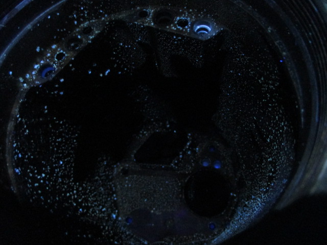
Foreign object damage (FOD) was noted through the area and opened ports. FOD appeared to be all through the overspeed governor bracket and port areas through the bracket as well. The fault was confirmed during analysis of the electrohydraulic servo valves (EHSVs). The substance was identified as superabsorbent polymers (SAP) (polymers that can absorb and retain large amounts of liquid). A common SAP use is in disposable diapers.
Fuel delivery systems at airports around the world use filter monitors with SAP elements to remove water from fuel. SAP may be released into the fuel by improper fuel handling equipment maintenance, cleaning, operation and other scenarios.
SAP particles are typically in the 5 to 20 micron size range and may not be visible, but can be up to 750 microns (0.030 in., visible).
SAP can be identified through black light inspection (SAP will fluoresce in black light) and through chemical testing using sulfate pentahydrate (SAP will turn blue when exposed to this chemical).
The HMU had a contamination overhaul performed, power flushing of main housing and EHSV’s solenoids, and was then returned to service.
The sister HMU from the same aircraft was returned for investigation. There were signs of minor SAP contaminates in some low flow areas and on external surfaces of the HMU, but not as severe.
Transport Canada Comments:
If an operator suspects they have received contaminated fuel, the airframe manufacturer’s instructions must be followed to help ensure safe operation of their aircraft.
Superabsorbent polymer contamination made visible under a black light
CF34-3B1 - Cracked Fan Blade Pins Causing High Engine Vibration
SDR #20170315003
Subject:
During a ground power assurance check, abnormal fan (N1) vibration was noticed on the right hand engine. Inspection revealed severe damage on all the fan blades pins. Three of them were found in very bad condition.
Transport Canada Comments:
This unit is something that is called out for inspection in both the engine and airframe manuals however the airframe manual has lesser inspection requirements. Operators are reminded that when developing maintenance schedules, airframe and engine manufacturer requirements should both be considered. The manufacturers’ recommendations should be thought of as a minimum requirement; operator and industry experience should also be considered.
Damaged fan blade retaining pins
CF6-80C2B6 - Engine failure due to liberated turbine nozzle
SDR #20160913005
Subject:
Crew reported hearing a loud bang from the left engine. Engine vibration was apparent and loss of available power was estimated at about 20% by the crew. Flight was subsequently diverted.
Transport Canada Comments:
The engine teardown revealed that the stage three nozzle had failed. This particular part was the subject of a GE service bulletin (SB) 72-1354 which recommends replacement with an improved unit.
While manufacturer’s SBs are not mandatory unless made so by an Airworthiness Directive, it is good practice to comply with them.
View of engine tail cone after nozzle failure
Honeywell
TFE731-20BR-1B Drive Splines and Interconnect Couplings Inspection
SDR #: 20211102014
Subject:
During the pre-flight checks after engine start, the pilots report the engine computer switch is to be set to manual mode, and a slight engine acceleration is noted. When the switch for the left engine was selected to the manual mode position, the engine had an uncontrolled acceleration. The pilots moved the engine computer switch back to auto mode and the engine returned to its normal operating condition, and the engine was then shut down. The Honeywell Maintenance Manual includes a caution for the fuel control unit (FCU) installation, stating that if the coupling between the FCU and fuel pump is not installed, the engine will overspeed rapidly in manual mode. The left engine FCU was removed to inspect the coupling between the FCU and the fuel pump, and the drive splines on the FCU. The inspection revealed that the output shaft from the fuel pump, the interconnect coupling and the FCU drive splines were stripped.
Transport Canada Comments:
It is common practice for many manufacturers to mate components together using interconnect couplings. These couplings are made from a variety of materials depending on the application. Some couplings are designed to shear if a component seizes, to limit the extent of damage to its mated component.
The root cause of these stripped splines has yet to be determined, but improper alignment during installation and material defects are possibilities. As stated in this event, the manufacturer’s Instructions for Continued Airworthiness (ICA) does bring attention to ensuring interconnect couplings are installed to prevent overspeed of the engine. However, maintainers are reminded to inspect the condition of the mating surfaces and to pay attention when installing components to ensure proper engagement.
Photo 1 – Interconnect coupling
Photo 2 – Fuel pump drive spline
Photo 3 – Fuel pump drive spline close-up view
Pratt & Whitney – Canada
PW207D2 - Leaking Triple Function Switch
SDR #: 20230502009
Subject:
During a post flight serviceability check and servicing, fuel was found on the number two engine triple function switch and pooling on top of the number two engine fuel management module (FMM). Aircraft was taken out of service.
Transport Canada Comments:
Transport Canada has received several service difficulty report submissions regarding leaking of the triple function switch. All events reported similar findings of leaks on the FMM. The leaks were typically detected during pre and post flight inspections where there was a noticeable fuel smell and visible wetness around the top of the FMM.
The subject switch is a new version and was introduced with Pratt & Whitney Canada service bulletin (SB) 28332R1 as a result of the previous triple function switches causing incorrect cockpit displays because of electrical contact contamination.
The engine type certificate holder is currently investigating these events. TCCA therefore recommends that operators and maintainers of this engine model and similar models pay particular attention to this area and report any leaks or other findings through their Web Service Difficulty Reporting System.
Picture 1 Triple function switch location
Text in the picture: Right side of engine, Airframe connector
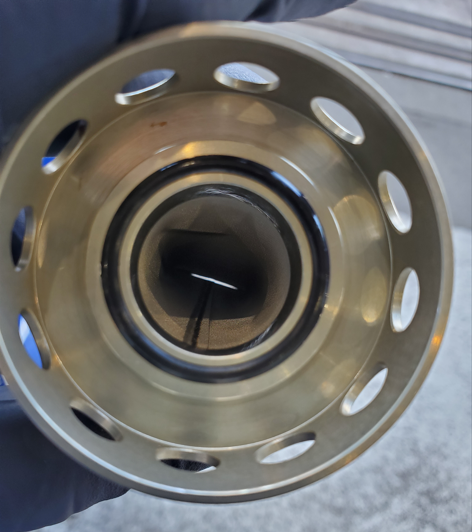
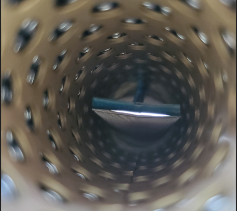
PT6A-34 - Oil Filter Inner Mesh Cone
SDR #: 20230713014
Subject:
During a regularly scheduled inspection of the oil filter, it was noted that the inner mesh cone was split open, just past the end brazing fold (outlet end).
Transport Canada Comments:
The inner mesh screen serves as the secondary filter should the main engine oil filter element go into bypass. In this case, there was no indication that the filter had been bypassed and therefore the secondary inner mesh screen was not being used for oil filtering.
These maintainers are commended for their thorough inspection of this component and detection of the inner screen defect. Had the filter gone into bypass, contaminated oil would have been able to flow through the engine, which could have posed a significant threat to its continued safe operation.
Transport Canada would like to bring this event to the attention of maintainers and operators of this engine and similar models and to encourage reporting of any findings through their Web Service Difficulty Reporting System.
Picture 1 - Oil Filter
Picture 2 - Secondary Mesh Screen
PW150A - Chafed Oil Scavenge Line
SDR #: 20240102006
Subject:
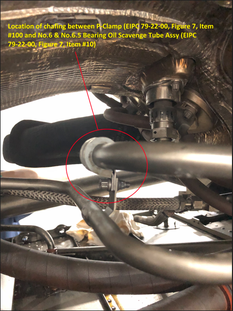
On December 18, during an overnight maintenance check on the aircraft, oil was found dripping from the number two engine cowl at the aft inboard corner near the drain mast. After opening the cowl doors, a significant amount of oil was found on the aft nacelle floor near the oil cooler cover and cooler lines area. Oil was seen dripping from the number two engine 6 and 6.5 bearing oil scavenge tube from underneath a p-clamp. The p-clamp was found to have an unusual amount of play in the fore/aft direction. When removed, it was discovered that the p-clamp cushion had chafed through completely, and the metal portion of the p-clamp had chafed through the oil scavenge tube, causing the oil leak.
Transport Canada Comments:
TCCA received two service difficulty reports with identical problem descriptions. As can be seen in the attached photos, the metal band has worn through the clamp cushion resulting in a chafed scavenge line from metal-to-metal contact.
Like most engine compartments, this area is congested with lines, hoses, cables etc. and the event clamp seems to be secure, but the photo of the removed worn clamp clearly shows that it was moving.
While the investigation continues to determine root cause, TCCA brings this event to the attention of operators and maintainers of this or similar engine models. Take time to check this clamp and all securing hardware when inspecting in this area and report any finding through your Web Service Difficulty Reporting System.
Picture 1 - Engine Bay
Text that appears in the image - Location of chafing between P-Clamp (EIPC 79-22-00, Figure 7, Item #100) and No.6.5 Bearing Oil Scavenge Tube Assy (EIPC 79-22-00, Figure 7, Item #10)
Picture 2 - Chafed Oil Line
Picture 3 - Removed Clamp
PT6A-50 - Damaged Garlock Seal
SDR #: 20230518007
Subject:
On 20 July, 2022, during an inspection, an oil leak was discovered by maintenance coming from the #4 hydraulic pump Garlock seal (plain seal). The Garlock seal for the #4 hydraulic pump was replaced, the engine was leak checked, and found serviceable. On 9 May, 2023 during a flight, the flight crew noticed the #4 low oil pressure caution light illuminate and the #4 oil pressure gauge was indicating low pressure. They shut down the #4 engine and elected to return to the main base. They returned with 3 engines operating and the aircraft landed without incident. Maintenance inspected the engine and found the #4 hydraulic pump Garlock seal damaged. This was allowing oil to bypass the seal and drain overboard. The #4 hydraulic pump Garlock seal was replaced, the engine was leak checked, and found serviceable. The aircraft was returned to service with no further incident.
Transport Canada Comments:
Investigation into this repeat event did not determine a root cause.
A defective seal was not ruled out but given the visual condition of the removed seal it is possible that incorrect maintenance practices may have been a factor. The installation instructions and required tooling are clearly defined in the manufacturer’s instructions for continued airworthiness (ICAs) and their proper use should not result in the type of damage found.
Although the safety implications of this event were low since it occurred on a multi engine aircraft, if this had occurred on a single engine aircraft the outcome may have been much more hazardous. Transport Canada would like to remind maintainers to follow published ICAs when performing maintenance tasks and to report any service difficulty findings.
Picture 1 - Garlock seal side view
Picture 2 - Garlock seal top view
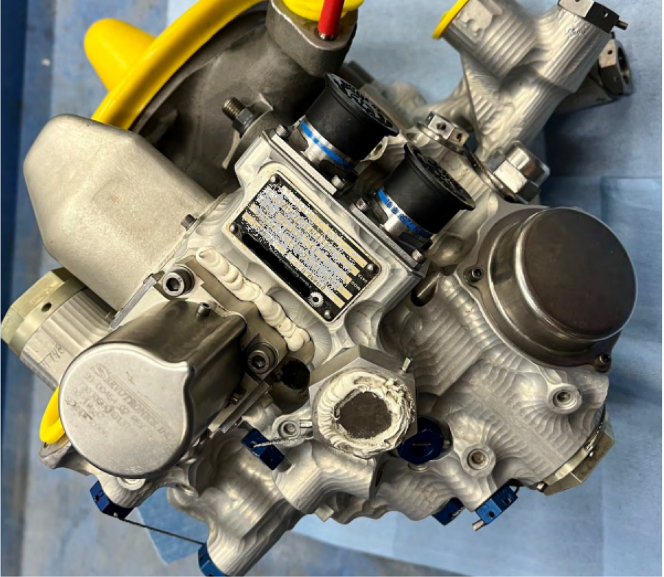
PW150A - Scored Fuel Pump Transfer Tube Bores
SDR #: 20230125017
Subject:
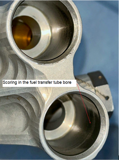
A fuel metering unit (FMU) assembly was issued from stock to be installed on an aircraft and found to have scoring marks in the fuel transfer tube bores, which were beyond the Component Maintenance Manual (CMM) limits. The unit had been received from repair in 2020 and was in stock since that time.
Transport Canada Comments:
Although this event is still being investigated by the manufacturer and a root cause for the scoring has yet to be determined, some possible causes could be a damaged O ring or misalignment of the transfer tube, allowing the transfer tube to contact the bore.
Transport Canada Civil Aviation (TCCA) brings awareness of this event to operators and maintainers of similar models to check these bores prior to installation and report any findings to TCCA through their Service Difficulty Reports (SDR) reporting system.
Well done to this operator and maintainer for performing a meticulous inspection of the FMU and pump before installation.
Picture 1: FMU
Picture 2: Scored transfer tube bores
PW120A - Cracked Fuel Drain Line
SDR #: 20220725001
Subject:
During a scheduled engine fuel nozzle replacement, the combustion chamber fuel drain line was found cracked.
Transport Canada Comments:
Transport Canada would like to inform maintainers and operators of PW120A and similar engine models of this event.
The investigation into the root cause continues, however, corrosion and stress along the weld seam may have been contributing factors.
Please be diligent when inspecting this area and, specifically, this line. Please report any similar findings through the Transport Canada Web Service Difficulty Reporting System.
Picture 1: Broken fuel line
Picture 2: Broken fuel line closeup
PW306D - Broken Thermocouple Harness
SDR #: 20220309008
Subject:
While inspecting the internal ignition lead segments to the igniter plugs, during the first 800-hour interval tasks, broken thermocouples were observed through the bypass access panel. Upon further inspection, it was discovered that there were broken probes on each wiring harness of both engines. All four thermocouple wiring harness assemblies (two per engine) required premature replacement at 818.2 hours total time since new.
Transport Canada Comments:
From the photos provided by the service difficulty report submitter, the thermocouple leads seem to have broken close to the thermocouple probe body where the assembly is attached to the engine case. Some discoloration on the thermocouple leads may indicate corrosion and the offset alignment of the lead to the thermocouple probe after breaking suggests stress or fatigue induced during installation.
The root cause of this event is still being investigated by the manufacturer, however, Transport Canada Civil Aviation (TCCA) would like to highlight this event for operators of PW306D engines and similar models. If performing inspections in this area or carrying out the 800-hour interval task, pay particular attention to the security and serviceability of the thermocouple harnesses and report any findings through the Web Service Difficulty Reporting System.
Picture 1 – Sheared Thermocouple Lead
Picture 2 – Thermocouple Lead Sheared and Rubbing On Case
PW123 - Fuel Line Fitting Under-Torqued
SDR #: 20211129009
Subject:
On take-off while climbing through 1500 feet, the crew identified a loss of torque on the #2 engine accompanied by a loss in propeller Revolutions Per Minute (RPM). The torque went to zero and the crew secured the engine. The aircraft landing was uneventful. An inspection by maintenance determined the loss of power was caused by a fuel leak at the fuel flow divider fuel inlet tube assembly. The affected fuel line and fittings were inspected, O-rings were replaced on the flow divider transfer tube and the line installed in accordance with the maintenance manual. Engine power runs were completed, and the aircraft was released back to service.
Transport Canada Comments:
The occurrence summary in the Transportation Safety Board (TSB) daily notification log of this event states that the maintenance personnel determined that an under-torqued fuel line fitting led to the drop in fuel pressure and subsequent engine power loss.
The fuel, oil and electrical systems of engines are normally housed in very cramped and restricted areas of most aircraft and access can be limited at best. Many “B” nuts for fluid lines may not have clearance to attach a torque wrench in a conventional way and a variety of extensions or adapters may have to be used for access. These extensions or adapters may result in an over or under torque situation. The proper torquing of these lines is vital to ensure they remain secure so maintainers are reminded to be vigilant when installing or inspecting these lines and consult manufacturer’s instructions or standard practices such as AC43.13-1B for proper torque calculations if using extensions or adapters.
This aircraft had an uneventful landing however had the fuel leak ignited, it may have been a very different outcome.
PT6A-27 - Corroded Starter Generator Drive Gear Shaft
SDR #: 20220623027
Subject:
Starter generator drive gear shaft assembly, Part Number 3029567, was received in overhauled condition. During the receiving inspection, it was noted that corrosion was present on the gear shaft once the protective cap was removed.
Transport Canada Comments:
Overhauled components regularly sit on storage shelves for extended periods and may not get inspected before being shipped.
The bearing surface of the gear shaft had numerous pit marks from corrosion, which may have been caused by improper preservation for storage. This corrosion was not detected until the protective cap was removed from the gear shaft assembly.
Transport Canada Civil Aviation reminds maintainers and operators to carry out receiving inspections to ensure serviceability of incoming components. Do not assume parts are serviceable because of the documentation attached. Well done to this operator who caught this issue prior to the gear shaft being installed in an accessory gearbox.
Picture 1 – Corroded gear shaft
PW210A - Fuel Control Unit (FCU) Casting Defects
SDR #: 20230119005
Subject:
The FCU supplier recently discovered various casting defects within several internal core passages of the inlet housing assembly of the FCU. These defects are mainly excess aluminum material of various shapes (granules, globules, raised ridges, casting flash) resulting from the casting process. The estimated size of these defects ranges from 0.030 to 0.180 inches. There can also be a thin wall thickness condition potentially leading to a fuel leak or affecting the FCU’s functionality. A total of 52 FCUs are affected by this condition. A service bulletin (SB) will be issued to replace the FCU within 150 hours. For helicopters that have two engines affected by this condition, the recommendation is to replace one of the two FCUs before further flight. The affected engine models are PW210A, PW210A1, and PW210S.
Transport Canada Comments:
Transport Canada Civil Aviation (TCCA) would like to raise awareness of this finding to operators and maintainers of the affected engine models. A manufacturing issue may result in a possible blockage of the FCU internal passage affecting fuel flow and may also result in a thin wall thickness condition that could lead to external fuel leakage.
The engine manufacturer, Pratt & Whitney Canada (P&WC), issued SB A57168 which addresses this issue. Please review the SB and component logs or check part numbers and serial numbers of the FCUs on the affected engine models and contact P&WC for disposition.
As TCCA continues to monitor this issue, please report any findings directly to P&WC or to TCCA via the Web Service Difficulty Reporting System.
PT6A-21 - Propeller Governor Flyweight Bearings Insufficient Ball Retention
SDR #: 20230202005
Subject:
During a normal inspection, it was discovered that the right-hand engine magnetic chip detector had a piece of metal attached to one of its magnetic pick-ups. It was a metal ball of 0.039 inch in diameter. We sent the information to the engine manufacturer and after several days, the information came back stating that the ball was probably coming from the propeller governor and possibly also from the overspeed governor. The propeller governor was removed and sent to the overhaul facility who confirmed that one of the four internal flyweight bearings failed. All eight (8) balls and race were missing. On our side, no other metal part has been found so far into the oil filter, on the aft Accessory Gear Box (AGB) pump inlet screen or around the forward AGB magnetic chip opening.
Transport Canada Comments:
Woodward, the propeller governor manufacturer, issued Service Bulletin (SB) 83053-61-027 in 2012. The SB provides instructions for replacing bearings that were assembled with lightly crimped bearing retainers. Engineering analysis, conducted cooperatively by the engine, governor and bearing manufacturers, concluded that the failure was likely caused by a vigorous oscillatory motion of the two-piece, loosely crimped, bearing retainer resulting in fretting wear of the retainer assembly.
Further to their investigation into this Service Difficulty Report (SDR), Pratt & Whitney Canada continues to promote compliance with Woodward SB 83053-61-027. Transport Canada Civil Aviation (TCCA) concurs with this position and would like to highlight the value in assessing and following manufacturers’ recommendations, including those at the component or vendor level.
TCCA encourages submission of SDRs for similar events through the Web Service Difficulty Reporting System.
Figure 1 – Damaged flyweight bearing
Figure 2 – Damaged and serviceable flyweight bearings
PW127M - Disconnected Fuel Line
SDR #: 20211001010
Subject:
During a power assurance check, the left engine caught fire.
Transport Canada Comments:
The investigation of this event determined that the fuel pressure line had been disconnected during the removal of the nacelle lower structure. This is a deviation from the airframe manufacturer's procedures, and disconnection is not required. Following scheduled maintenance, a leak check was not performed before the power assurance check was carried out. A review of the Engine Maintenance Manual (EMM) and Airframe Maintenance Manual (AMM) found nothing wrong with the procedures for the task.
The described event perfectly shows how failure to follow manufacturers' Instructions for Continued Airworthiness (ICA) can lead to very serious situations. Not only did omitting steps lead to problems, but the additional step of disconnecting a fuel pressure line resulted in an engine fire. If a ground run had been performed post-maintenance, this event may have been prevented.
Transport Canada Civil Aviation reminds operators and maintainers to strictly adhere to ICA, perform ground runs after maintenance, and have a colleague check the work performed before closing panels or doors.
Disconnected fuel line
PW150A Improper Generator Installation
SDR #: 20191010008
Subject:
The crew reported that the right-hand direct current (DC) generator caution light was illuminated followed by an oil pressure warning light during flight. The crew commanded shutdown of the engine and landed without any incident. Upon troubleshooting, maintenance found the right-hand DC generator separated from its mount on the reduction gearbox.
Transport Canada Comments:
An investigation by the engine manufacturer found the oil pressure warning was caused by an oil leak from the DC generator that was not seated on its mount. The root cause was determined as improper generator installation.
Generators or starters on most aircraft tend to be heavy, cumbersome to handle or install, and located in an area that is usually difficult to access and congested with lubrication and fuel lines as well as wire bundles. The securing hardware of the generator to its drive varies from basic stud mounts with nuts, to band clamps that encompass the generator and gearbox mounting flanges.
Although these different mounting systems may seem straightforward, you must follow the manufacturer’s instructions to ensure proper installation. Normally, they need to be in a certain orientation for wiring hookup, which may or may not be aided by a locator pin. Many have specific torque procedures for clamps or specific torque sequences for stud mounted, and other components may require removal to facilitate an installation.
In this event, the crew was fortunate to land without incident but had the generator detached from the mount, it may have resulted in a very different outcome. Transport Canada Civil Aviation reminds all maintainers to be diligent and follow the manufacturer’s Instructions for Continued Airworthiness (ICA) regardless of how simple the task may seem.
PT6A-67P - Leaking Propeller Shaft Seal
SDR #: 20200716009
Subject:
On July 11, 2020 the propeller shaft seal was replaced due to leaking, and an engine ground run and leak check were completed. On July 13, 2020 the aircraft took off from the airport and completed a turnback due to oil on the windscreen and the engine cowling. Maintenance replaced the faulty propeller shaft seal on July 15, 2020. During the replacement of the faulty shaft seal, a buildup of seal material on the mating surface of the seal was noted and grooves on the aft side of the seal mating surface had worn off.
Transport Canada Comments:
In this event, an oil leak was found, and a seal replacement was carried out by maintenance personnel. Unfortunately, the seal failed on the next flight even though ground runs had been performed after its replacement. Further inspection found a buildup of seal material on the mating surface, which probably resulted in the sealing grooves being worn off and another oil leak.
An investigation into the root cause could not rule out the possibility of both seals being defective. However, it was determined that improper maintenance practices likely contributed to the failure of the second seal. It was found that the replacement seal was not repositioned according to the maintenance manual instructions. A third seal was installed, and the aircraft returned to service.
With the demands of meeting schedules and deadlines in a very competitive market, many tasks are at risk of being rushed to completion. In this circumstance, it appears that a full inspection of the area including mating surfaces may not have been completed prior to installation and repositioning of the propeller shaft seal. Transport Canada Civil Aviation (TCCA) reminds maintenance personnel that they have a responsibility to accomplish tasks in accordance with the appropriate standards of airworthiness and to remain vigilant for human factor issues that may impact the quality of their work.
Picture 1 – Propeller shaft seal
Picture 2 – Buildup of material on seal
PW127M - Re-orientation of Bus-Bar Support Bracket Bolts
SDR #: 20201127003
Subject:
The pilot observed high inter-turbine temperature (ITT) on the left engine during climb and elected to safely return to the airport of origin. During troubleshooting, one thermocouple leg was found touching the mount base. It was isolated and secured, and the aircraft was released back to service.
Transport Canada Comments:
Pratt & Whitney Canada Service Bulletin (SB) 21931 is related to this issue. In summary, the calculated value for the ITT can fluctuate due to intermittent contact between the negative bus-bar support bracket bolts and the turbine support case (TSC) insulation blanket. To eliminate interference, the SB provides instructions to re-orient the negative bus-bar support bracket bolts to increase the clearance with the TSC insulation blanket. Transport Canada, Civil Aviation (TCCA) recommends compliance with this SB.
PW305A - New Bleed Valve Solenoid
SDR #: 20201005017
Subject:
During taxiing for take-off, the crew saw the left engine inter-turbine temperature (ITT) climb to 885oC, the low oil pressure annunciator illuminated, and the crew immediately shut down the engine and taxied back to the fixed base operator (FBO).
Transport Canada Comments:
Transport Canada Civil Aviation (TCCA) has received numerous Service Difficulty Reports (SDRs) related to compressor bleed valves on Pratt & Whitney Canada (P&WC) models PW305A, PW305B and PW306A engines.
The purpose of this Feedback article is to raise awareness of P&WC Service Bulletin (SB) 25401R7 and SB 24645R6. These SBs introduce a new bleed valve solenoid valve to improve the durability of the compressor bleed valve. Reference P&WC Service Information letter (SIL) PW300-198, which advises operators of these SBs.
TCCA encourages operators to follow all manufacturers' recommendations and consider implementing these SBs in the interest of safety.
JT15D-4B - Improper Igniter Cable Routing
SDR #: 20201215004
Subject:
At take-off, the crew advanced the throttle, and while adjusting the right-hand engine to the correct power rating, the right-hand throttle lever became jammed. The crew aborted the take-off and vacated the runway normally. The left-hand engine was shut down normally to limit thrust during taxiing. A moment later, the right-hand aircraft brake failed and spun the aircraft off the taxiway. While the crew was trying to unstick the right-hand throttle, the thrust reverser inadvertently deployed, and dust/dirt entered the cabin. The crew had to shut down the right-hand engine using the firewall shut-off valve. The source of the throttle jam was found to be an engine igniter cable not routed properly on the engine, which interfered with the throttle cable.
Transport Canada Comments:
The importance of security and proper routing of lines, cables, bundles etc. cannot be stressed enough. With the confined areas of some aircraft, it may seem impossible to ensure that no chafing or interference of moving parts exist.
In this event, the root cause was determined as improper routing of the ignition cable. This may seem like a human factors error; however, it may have made sense to install the cable in such a way as to avoid interference with other lines or bundles. Luckily this event ended without incident; however, had the event occurred during flight, the outcome may have been much worse.
When carrying out such tasks, please follow the manufacturer’s instructions and if there are doubts or concerns about the security or proper routing, contact the manufacturer for verification. Always check clearance of moving parts when routing bundles, lines or cables to ensure no interference with controls.
PW127M - Fuel Nozzle Transfer Tube Missing O-Ring
SDR #: 20210326013
Subject:
The customer reported an excessive fuel leak from the left engine drain mast after engine start. This happened after the first flight since the fuel nozzles were replaced. The customer identified a missing O-ring from the #4 fuel nozzle transfer tube. The O-ring was installed and the aircraft returned to service after a ground run check.
Transport Canada Comments:
Many maintenance tasks involve mundane procedures that require repetitive actions. The replacement of fuel nozzles is one such task that involves the removal of old and installation of new O-rings on numerous transfer tubes, depending on the engine model.
In this event, an O-ring was found missing from a transfer tube causing a fuel leak. Fortunately, this was detected on engine start prior to flight. Had the leak occurred during flight and ignited, it may have had a much worse outcome.
Complacency caused by repetitive tasks, distraction from the job at hand, fatigue, and the pressure to get the job done are all possible factors that can lead to such events. Aircraft maintainers face significant threats to maintaining diligence when carrying out any type of work, but the threats related to repetitive activities are elevated. Being aware of possible human factor errors, and recognizing when they are most likely to affect one’s performance, are essential skills for any aircraft maintainer to master.
PT6A-67F - Seal Running Surfaces
SDR #: 20200629030
Subject:
Engine accessory gear box (AGB) high pressure fuel pump drive gear is scored causing an oil leak past the drive seal.
Transport Canada Comments:
Seals are often replaced to correct oil leaks, but the seal itself is not always the root cause. As seen in the attached photo, there are visible wear marks in the area of the seal running surface of the gear shaft. Replacing a seal in an attempt to correct an oil leak caused by a worn or damaged seal running surface often results in the leak reoccurring very shortly thereafter.
Limited access to these components often makes it difficult to inspect and verify the amount of wear on the running surface, however, using technology such as inspection cameras, or other similar devices, greatly improves the ability of the maintainer to detect such damage.
Figure 1: Fuel pump drive gear
PT6A-67F - Leaking Fuel Pump Drive Seal
SDR #: 20200623016
Subject:
The engine driven high pressure fuel pump drive seal was leaking oil excessively. The seal was found to be damaged. No lost time.
Transport Canada Comments:
Damaged O-rings and seals are a common root cause for many leaks in oil, fuel and hydraulic systems on aircraft. Many factors, such as limited access and lack of proper tooling, contribute to the possibility of damaging seals on installation. However, in this case, the fuel pump drive gear shaft appears to have been scored, reducing the effectiveness of the oil seal. In cases like this, simply replacing the seal is unlikely to be effective and the shaft would normally require repair or replacement to correct the oil leak.
Picture 1 : Damaged seal
Picture 2 : Damaged drive gear
PT6A-67F - Starter Generator Carbon Seal
SDR #: 20200707012
Subject:
The starter generator seal is leaking oil excessively. The carbon seal appeared to have a worn face. The carbon seal and the runner were replaced. Leak checked was carried out ok.
Transport Canada Comments:
Carbon seals are a proven industry standard in a wide variety of aircraft and engine applications. The seals are ideal for use because of their low coefficient of friction, low wear rate, high thermal conductivity and resistance to oxidation.
Unfortunately, all of these characteristics are ineffectual if the seal is damaged. Installation without proper tooling, insufficient cleaning of sealing surfaces, seal carriers and bores etc. or inattention when installing driven components such as a starter generator are some of the factors that may cause seals to be damaged and leaks to occur.
Inspect both the seal and the seal running surfaces to ensure they are not damaged. Use recommended lubricants and cleaners where applicable and clean thoroughly and always follow manufacturer’s Instructions for Continued Airworthiness (ICA) when installing, removing, inspecting or handling these components.
Seal and Runner
PW123B - Fuel Control Unit Driveshaft Bushing
SDR #: 20201021003
Subject:
Following a fuel control unit (FCU) replacement on the right-hand engine, maintenance found an internal leak between the fuel pump and the FCU. After removal of the FCU, it was noted that the bushing on the FCU driveshaft was improperly installed. The FCU was freshly overhauled.
Transport Canada Comments:
Events such as these are all too familiar to maintainers and operators, where a new or recently overhauled component is installed, and during testing or ground run, they are found to be defective or unserviceable.
The improperly installed bushing may have been the result of incorrect tooling, failure to follow component maintenance manuals, poor maintenance practices or may have been dislodged due to poor handling during shipping or receiving.
Transport Canada Civil Aviation would like to remind maintainers that the certification and serviceability of a component to be installed on an aeronautical product is not only the responsibility of the overhaul shop but also the person who certifies the installation. Do not assume parts bearing certification tags are indeed serviceable, carry out a thorough inspection of components prior to installation.
Photo 1: Properly installed bushing
Photo 2: Improperly installed bushing
PW150A - Cracked Fuel Transfer Tube Bracket
SDR #: 20190524018
Subject:
During the accomplishment of a scheduled maintenance task (replacement of the Fuel Metering Unit (FMU) to the Fuel/Oil Heat Exchanger (FOHE) transfer tubes), an Aircraft Maintenance Engineer (AME) noted that the fuel transfer tube bracket on the left engine was cracked. The assembly was replaced with a serviceable component and the aircraft was returned to service.
Transport Canada Comments:
Pratt & Whitney Canada (P&WC) is aware that cracks develop occasionally on the weld, equally in the pre- and post-mod configurations (see P&WC Service Bulletin No.3533R1) . These cracks typically do not affect the functionality of the bracket and are usually discovered during opportunistic inspections when the tubes/bracket assemblies are replaced.
Transport Canada would like to make maintainers aware of the possibility of these cracks and to pay particular attention to these transfer tubes when circumstances provide access to the FMU as well as during scheduled maintenance.
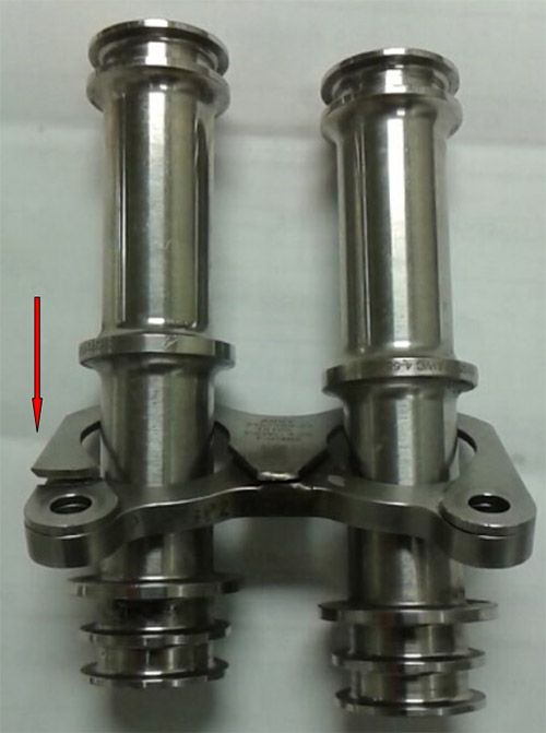
Photo 1 Transfer tube assembly
PW150A - Oil Pump Leak
SDR #: 20200212008
Subject:
During flight, the right-hand engine experienced fluctuating oil pressure. The pilot proceeded to land the aircraft uneventfully. It was decided to replace the engine and the aircraft returned to service.
Transport Canada Comments:
During cruise, the number two engine oil pressure fluctuated between 40 and 55 psi with the oil pressure light illuminating on and off during the flight. The number two engine was feathered in accordance with the Quick Reference Handbook (QRH) and the oil pressure increased from 50 to 60 psi and was noted as 62 psi on landing. During the troubleshooting, an oil leak was found at the oil pump drain. Further inspection of the area revealed that two bolts holding the oil transfer tube retaining plate had sheared and allowed the retaining plate to vibrate and chafe through the body of the oil pump leading to a hole in the pump casing.
Investigation into the event discovered that a non-mandatory service bulletin (SB) had been issued recommending a periodic visual inspection to check for fretting of the transfer tube retaining plate and ignition support bracket, and to verify the torque on the attaching hardware.
Transport Canada encourages all operators to review SBs issued by manufacturers and recommends adopting these types of inspections as part of their maintenance programs. Although the aircraft landed uneventfully, it could have been much worse and would have likely been avoided had the SB been complied with.
PW306D - Fuel Filter Impending Bypass Switch
SDR #: 20170110013
Subject:
After takeoff, at approximately Flight Level 260, the crew observed a Fuel Filter Bypass Crew Alerting System (CAS) message on the right-hand engine and no other messages were indicated. The crew completed the checklist items, declared an emergency and diverted the flight for an uneventful landing.
Transport Canada Comments:
Transport Canada has received several similar Service Difficulty Reports (SDRs) with the Fuel Filter Impending Bypass Switch identified as the specific part causing difficulty for the illumination of the CAS message.
Pratt &Whitney Canada has published Service Bulletin (SB) SB25455 introducing a replacement switch which annunciates using a normally open contact and has an electrical inverter for interface compatibility purposes. The replacement switch alleviates the existing false annunciations due to the deterioration of the current switch’s normally closed contacts.
It is strongly advised that particular attention be given to the SB’s CAUTION statement which instructs maintainers to NOT remove the bypass valve to facilitate removing the switch.
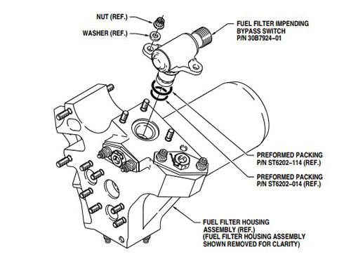
Figure 1: Fuel Filter Impending Bypass Switch
PW150A - Scavenge Oil Filter Leak
SDR #: 20200320007
Subject:
The flight crew reported that during the approach to the airport, they received a low oil pressure indication on the number one (1) engine. The flight crew followed the Quick Reference Handbook (QRH) and shutdown the engine. A PAN PAN was declared and the aircraft diverted to an alternate airport and landed without further incident. During troubleshooting, maintenance personnel found an oil leak originating from the scavenge oil filter area. The packing and the oil filter were replaced in accordance with Aircraft Maintenance Manual (AMM) 79-22-11-400-801 and a leak check was carried out serviceable. The aircraft returned to service.
Transport Canada Comments:
The operator confirmed that the low oil pressure event occurred on the first flight following the replacement of the scavenge oil filter. An investigation by the operator suggested that the scavenge oil filter cover packing was damaged during the installation and that environmental factors may have diminished the ability to perform an effective inspection during the leak check.
Maintainers often find themselves in situations where factors like weather conditions and accessibility create difficulties in performing certain tasks, however maintainers are reminded to take all necessary steps to perform these tasks, to be thorough when performing maintenance and follow all instructions for continued airworthiness.
PT6A-67D - Cracked fuel line discovered after fuel seen in engine area
SDR #: 20170831016
Subject:
Minor edits have been made to the text below taken from the Service Difficulty Report’s Problem Description. Transport Canada Civil Aviation reserves the right to edit for spelling, grammar and punctuation to increase comprehension.
During a scheduled inspection, maintenance found fuel leaking from the left hand engine. Further investigation revealed that the primary fuel pressure tube assembly (part number 3035618) was cracked at the flange area. The tube assembly was replaced, successful ground runs and leak checks performed. Aircraft was returned to service.
Transport Canada Comments:
This type of failure can be caused by many factors such as mishandling of the line, improper alignment prior to final torqueing or excessive vibration. Maintainers must be careful when working with fluid lines to avoid dangerous situations.
Excessive vibratory loads can be more difficult to detect and diagnose. Propeller balancing is an important step in reducing vibratory loads and should be carried out in accordance with the manufacturer’s recommendations.
Another less obvious source of damaging vibratory loads can come from Starter Generator failures. Often when a Starter Generator bearing fails, it will put a massive vibratory load that can damage many engine components (including fluid lines). After such events, maintainers must use extra care in inspecting the entire engine for secondary damage.
Cracked fuel line
PT6A-60A - Commanded In-flight Shutdown Due to Miss-rigging
SDR #: 20171002008
Subject:
Minor edits have been made to the text below taken from the Service Difficulty Report’s Problem Description. Transport Canada Civil Aviation reserves the right to edit for spelling, grammar and punctuation to increase comprehension.
The aircraft was climbing through eleven thousand five hundred feet with power set at eighty eight percent torque and prop speed at sixteen hundred rotations per minute (rpm). The flight crew heard the propeller rpm changing and observed it dropping back to eight hundred rpm and torque rising. When the torque approached redline, power was reduced to thirty percent. The torque and prop rpm stayed at around eight hundred. The aircraft was levelled off and prop was feathered. The crew elected to leave the engine running. The aircraft returned to base and landed safely. Maintenance performed an inspection and discovered the reversing cable stretched and the prop governor BETA valve was extended (out of rig.). The reversing cable was shortened (re-rigged) and engine ground run carried out. During ground run prop appeared to operate normally however it was indicating in the three to four hundred rpm range at all power settings. Further investigation revealed damage to the prop tach drive gear. The engine was removed from the aircraft and sent to a repair facility.
Transport Canada Comments:
It is believed that the engine may have been repeatedly shutdown with the power lever still in the BETA range. This could cause the reversing cable to stretch and in turn allow the BETA valve to go out of rig.
Evidence of lightning strike was found that may have contributed to the rpm fluctuations (residual magnetism was found in the prop governor).
PT6A-114A - Missing or Forgotten Bracket Causes Engine Shutdown
SDR #20170718006
Subject:
This engine was removed and shipped for repair after the crew reported an in-flight shutdown on final approach, about half a mile from touch down. Efforts to restore power were not successful and a glide approach was successfully executed.
Upon examination of the engine, it was noted that the fuel pressure tube from the fuel control unit to the fuel flow divider had chafed through where it passes through the rear fire shield. The engine was received with this pipe loosely installed as it had been disturbed by the customer and all the hardware as well as the insulation plates and seals were not present for evaluation. It was also noted that the bracket, part number (P/N) 3027046, used to secure the fuel pressure tube coupling to the accessory gearbox "G" flange was not installed.
The root cause of the fuel pressure tube chafing on the rear fire shield was determined to be the fuel pressure tube bracket P/N 3027046 not being installed. This resulted in the fuel pressure tube not being correctly aligned and applying pressure to the rear fire shield seals. The seals eventually failed, allowing the tube to come into contact with the fire shield.
Transport Canada Comments:
It was not determined when this bracket was omitted. It is likely that it was missed during some maintenance activity such as an engine change or major inspection. Maintainers must be aware of build specifications and service bulletin status when installing an engine or when conducting maintenance. They must also ensure that the engine is in the correct configuration.
Broken fuel tube and chaffing on fire shield
PW123B - Fuel Leak Caused By Skydrol
SDR #20170510013
Subject:
During aircraft turn around, a fuel leak was noticed on the number two engine. After investigation, maintenance found that transfer tube O-rings on all bottom engine fuel nozzles were chemically deteriorated by Skydrol. Further investigation revealed that the Skydrol came from the nacelle waste container which was filled by a leak of the engine driven hydraulic pump shaft. The Skydrol was able to backtrack the drain pipe of the fuel nozzle during different flight attitudes of the aircraft, and chemically damaging the lower fuel nozzle transfer tube O-rings and causing a leak.
Transport Canada Comments:
This is not the first time Transport Canada has seen reports of Skydrol deteriorating seals and causing issues to other systems. Maintainers are reminded that even minor leaks must be investigated and corrected before they develop into major problems.
Fuel tubes with Skydrol damaged O-rings
PW535A - Incompatible Chemicals Causing Oil Leak
SDR #20170404036
Subject:
During routine maintenance, a small oil seep around the number one engine oil pump was found. The seep was traced to one of the oil pump external transfer tube seals.
Pratt & Whitney were contacted to see if this was a known problem, it was confirmed it was not a known problem. As it was a small seep, they were not immediately concerned and agreed the best course of action was to monitor the seep and as long as it didn’t deteriorate and to rectify it at the next scheduled engine shop visit.
The aircraft flew another 6 hours with no signs of the seep increasing, it then flew a 1.7 hour leg and upon landing oil was observed dripping from the engine cowl. The aircraft was grounded pending an inspection and it was found that the engine had leaked 2.5 quarts of oil on the flight. Further checks found a steady drip from the oil transfer tube seal with the engine running.
On removal of the oil pump and transfer tubes, it was found that the seal had eroded on the exposed air side of the seal. Pratt & Whitney evaluated the seal to try and determine the cause of the erosion, current thoughts are chemical erosion due to contact with an incompatible fluid, possibly some kind of cleaning solvent. All the other seals associated with the pump were found unaffected but were replaced anyway.
Transport Canada Comments:
Incompatible chemicals can potentially cause major problems for aerospace products. Issues can include corrosion, hydrogen embrittlement, and seal erosion as in the case above. Aircraft Maintenance Engineers must be aware of which products are approved for use on the equipment they maintain as listed in the most current manufacturers’ publications.
Oil tube seal with signs of erosion
PW123D - Operation In Harsh Environments
SDR #20170315010
Part #311560101
Subject:
The engine was received for investigation and repair after the operator reported high pressure blade distress. Due to the time accumulated by the engine since overhaul, the operator also elected to overhaul the turbomachine and reduction gear box at this shop visit.
Transport Canada Comments:
Teardown findings revealed one high pressure turbine blade was missing approximately one third of its airfoil and other blades were missing material and showed hot corrosion.
Damage was consistent with what is considered harsh environment deterioration.
Maintenance tasks such as compressor washes and hot section inspections help reduce the potential for events such as the one described above. Pratt & Whitney Canada have information available to help operators determine what and when maintenance tasks should be done. Service Information Letter PW100-172R3 has information regarding harsh environment operation and can be found on Pratt & Whitney’s website: http://www.pwc.ca/en/home
Damaged turbine blade with evidence of harsh environment operation
PT6A-114A - Improper field adjustments leading to an un-commanded shutdown.
SDR #20160323016
Subject:
It was reported by an overhaul shop that one of its customers had an un-commanded fuel control unit (FCU) roll back followed by an engine shut down during taxi, prior to take off. Understanding the engine could not be started after the incident, the customer immediately carried out preliminary troubleshooting and did not find any external discrepancy. A loaner FCU was subsequently installed and the aircraft safely returned to operation with no discrepancy. The suspect FCU was supplied in an overhauled condition by Pratt & Whitney Canada (PWC). The customer requested to return the FCU to PWC for investigation and warranty repair.
Investigation found that the FCU had been subjected to improper field adjustments that led to the power roll back and subsequent shutdown.
Transport Canada Comments:
Operators are reminded that conducting maintenance must be done in accordance with CAR 571.02 “Maintenance and Elementary Work performance Rules” which includes the following statement: “A person who performs maintenance or elementary work on an aeronautical product shall use the most recent methods, techniques, practices, parts, materials, tools, equipment and test apparatuses that are
- Specified for the aeronautical product in the most recent maintenance manual or instructions for continued airworthiness developed by the manufacturer of that aeronautical product.
- equivalent to those specified by the manufacturer of that aeronautical product in the most recent maintenance manual or instructions for continued airworthiness; or
- in accordance with recognized industry practices at the time the maintenance or elementary work is performed”
Pratt & Whitney – USA
PW1524G3 - Fuel Check Valves
SDR #: 20220921006
Subject:
A fuel imbalance was experienced in flight. The following log entry was submitted by the aircrew: During the whole flight, we had fuel imbalance. The maximum was a 200kg difference. The low side was always on the right-hand side. The system balanced fuel three times within 45 minutes. On the ground, the fuel imbalance was still 160kg less on the right-hand side and the fuel flow was the same on both engines. The removal of the engine feed/isolation check valve revealed that the check valve was not properly installed.
Transport Canada Comments:
Several Service Difficulty Reports (SDRs) have been received reporting “Fuel Imbalance” master caution messages during flight. Maintenance inspections found dislodged fuel check valves, which prevent backflow of fuel from wing tanks to centre tanks, as well as permit engine fuel cross-feeding when electrical boost pumps are in operation.
It was discovered that the retaining wire, which holds the check valve in its correct position, is of an insufficient diameter allowing the check valve to become dislodged and, consequently, allowing fuel to bypass the check valve.
Transport Canada Civil Aviation would like to make operators and maintainers aware of Airbus Canada Service Letter CS-SL-28-20-004, which provides instructions for the replacement and installation of an improved retaining wire part number P/N 2183023-101.
Photo 1 – Check valves
Photo 2 – Dislodged piece of check valve
PW1500G - Fuel Manifold Leak
SDR #: 20201013016
Subject:
Fuel was noticed by maintenance personnel, and during further investigation, a pressure leak at the fuel manifold was found. The engine was removed for shop level part replacement.
Transport Canada Comments:
Transport Canada Civil Aviation (TCCA) would like to bring this event to the attention of operators and maintainers of similar aircraft models. At this time, no root cause has been determined, however, the photo provided shows a fine spray of fuel coming from what may be a crack or corrosion pit at a fuel manifold.
With the easing of COVID-19 restrictions and the increase in flying operations, many operators are having issues related to less than optimum preservation practices. When bringing aircraft back into service, proper ground runs and inspections are vital to ensure that all the aircraft’s systems are serviceable.
This event may not actually be related to a preservation problem, but it is still a good example of what operators may experience and what they should look for. For this event, please pay particular attention to the manifold and line when inspecting in this area and also be aware that these conditions may exist when introducing an aircraft back into service.
Leaking Fuel Line
PW1524G Pinched O-Ring
SDR #: 20190328006
Subject:
Minor edits have been made to the text below taken from the Service Difficulty Report’s Problem Description. Transport Canada Civil Aviation reserves the right to edit for spelling, grammar and punctuation to increase comprehension.
Inflight shutdown on the way back to airport. Initial general visual inspection revealed the engine was wet around the oil filter. Oil debris monitor limit posted previous day and maintenance carried out at night to replace oil debris monitor. Chip detectors and oil filter checked for debris. Preliminary report from Approved Maintenance Organization (AMO) indicated oil filter not installed correctly causing pinched O-ring.
Transport Canada Comments:
This event appears to be a “human factors” related issue and serves as a valuable reminder for maintainers to be diligent even when carrying out some of the most basic maintenance tasks. This Service Difficulty Report (SDR) highlights the importance of post maintenance procedures such as engine run ups and leak checks, verifying for correct part numbers, and adherence to instructions for O-ring lubrication prior to installation. Transport Canada supports and recommends the replacement of used O-rings after each use. Documenting and investigating events such as these through a Safety Management System (SMS) program could assist in determining a possible means of prevention in aviation organizations.
Example of Pinched O Ring
JT8D-17 - Engine Shutdown Due to Oil Loss from Loose Fitting
SDR #20170711020
Subject:
We have a reported precautionary inflight shutdown of this engine due to indication of oil quantity loss. Emergency was declared at destination airport and the aircraft landed without additional incident. More information will be uploaded when our investigation progresses.
Transport Canada Comments:
Investigation into this event revealed that a loose connector tube was the cause of the leak. This event appears to be a “human factors” related issue as maintenance had been accomplished on the affected area prior to the oil loss.
A safety management system can help prevent this and other similar type events by documenting, investigating and determining possible means of prevention. This must all be done in a non-punitive fashion that can bring everyone involved together to raise awareness and promote a safety culture.
Rolls Royce – USA
USA, 250-C300/A1 - Compressor Bearing Housing Assembly Configuration
SDR #: 20190924001
Subject:
The forward compressor bearing housing assembly is being discovered in many compressors with a modification that does not conform to the Commercial Engine Bulletin (CEB) that modifies the original part number (P/N) 6853505. These items are installed in Rolls-Royce M250 C20 and M250 B17 models. The bulletin requires one slot to be added, however many parts are discovered with two slot cutouts. We have purchased parts in overhauled condition, and when the receiving inspection is performed, the same condition is discovered. The serviceability of the parts are suspect, as they do not conform to the design aspect of the product, but as indicated, they are frequently seen in service.
Transport Canada Comments:
There have been numerous Service Difficulty Reports (SDRs) submitted regarding the correct configuration of the forward compressor bearing housing assembly P/N 6893617 for Rolls-Royce Corporation (RRC) M250 C20, C20B and M250 B17, B17B engine models.
The original configuration used two roll pins to secure an oil seal in the bearing housing assembly, however this design lacked squareness control of the seal and caused damage.
To reduce the potential for damage, RRC issued CEB1100, which introduced a new bearing housing assembly, P/N 6893617, and provided the instructions necessary for the rework of the original bearing housing assembly, P/N 6853505. The rework included the removal of the roll pins, machining a groove on the inside diameter, and the cutting of an access slot for installation and removal of a retainer ring. Upon completion of the rework, the bearing housing assembly was to be identified as P/N 6893617.
Various revisions of the above-mentioned CEB have been issued, revision one provided rework instructions to add two retaining ring access slots to the original bearing housing assembly P/N 6853505, and to identify the reworked part as P/N 6893617. Revision three changed the rework from two slots to one slot but retained the instructions to identify the reworked part as P/N 6893617.
Since there have not been any instructions to remove either a one slot or two slot configured bearing housing assembly, both configurations are in circulation, both will be found during overhauls and both are being received from vendors as overhauled parts.
Transport Canada Civil Aviation (TCCA) would like to inform maintainers and operators that after a lengthy investigation by the Federal Aviation Administration (FAA), both configurations have been found to conform to the approved type design and are acceptable for installation.
1 and 2 slot bearing housing assembly configurations
USA, 250-C47E/4 - M250 Engine Series #5 Annular Ball Bearing
SDR #: 20201124011
Subject:
The combined engine filter assembly (CEFA) bypass light came on upon landing. The filter was contaminated with metal debris. The upper and lower chip plugs were covered in contamination but did not trigger the chip light. The health and usage monitoring system (HUMS) kit indicated an increase in vibration reading on the power turbine shaft and on bearings 3, 4, 5 and 6. The engine was taken out of service and sent out for further evaluation.
Transport Canada Comments:
The engine manufacturer Rolls Royce published M250 Part Information Letter (PIL) 2016-008-D to introduce the release of a new part number (P/N) for the #5 annular ball bearing. This PIL is applicable to the M250 engine series and the new P/N M250-10795 bearing is interchangeable with the old P/N M250-10106 bearing. A number of service difficulty reports exist where metal chips were detected in the oil system during engine operation with the new P/N bearing installed. Operators and maintainers are encouraged to report service difficulties for M250 engines with either the new or the old P/N bearing installed.
Example of the metal detected by an M250 engine oil chip detector
250-C300/A1 Forgotten Plugs Found in Oil Holes
SDR #: 20170424012
Subject:
The gearbox cover was sent to our facility for overhaul. The power take-off (PTO) bearing cage was removed for machining of previous plasma repair. The machinist noticed that both oil holes were plugged by plasma spray. Pictures were taken and the machinist removed old plasma on a milling machine. After the plasma was milled away, rubber plugs were found in holes from previous plasma repair.
Bearing cavity with rubber plug left after previous repair
Teledyne Continental
TSIO-520-M - Blocked Oil Vent Line
SDR #: 20240123021
Subject:
During a 100-hour inspection, it was found that the engine had been blowing oil out of the oil filter, the oil quantity dipstick, and the crankcase breather at the engine attach point. The aircraft had been flying in sub -30 temperatures and upon inspection, it was found that the crankcase breather had frozen up (as it usually happens) and the whistle hole had been blocked with a ty-wrap causing a partial blockage of the breather. Because of the blocked breather points, the crankcase was pressurized, and oil was forced through other areas of the engine. The pilot had noticed oil beginning to spray on the windshield. This could have been catastrophic if the engine pressurized enough and blew the propeller seal out. A ty-wrap was found blocking the whistle hose. The ty-wrap was used to secure an oil line to the breather, to avoid wear, and had broken. When it had broken, it had travelled down the breather tube and stuck in the whistle hole.
Transport Canada Comments:
Investigation into this event involved researching the manufacturers instructions for continued airworthiness (ICAs) to ensure proper routing and securing of all lines and bundles in this area. The operator could not find any ICA that specified the routing.
This is a good example of the Swiss Cheese model in accident causes: a series of events that align and cause an event. The blocked crankcase breather along with the blocked vent tube caused pressurization of the oil system and may have resulted in an engine failure.
Operators and maintainers are reminded to be diligent when securing lines, hoses, or wire bundles in any area. ICAs may not give specific instructions so attention to proper routing to prevent potential rubbing and chafing is essential. TCCA encourages everyone to report similar finding through their Web Service difficulty Reporting System.
Picture 1 - Broken Ty Wrap
O-470-R - Teledyne Continental O-470-R Exhaust Valve Springs Broken
SDR #: 20220825011
Subject:
The pilot noticed the engine running rough in flight. He returned to base and landed. Upon further investigation, the Aircraft Maintenance Engineer found low compression on the #1 cylinder and both exhaust valve springs broken. He did some research and found a report of another Teledyne Continental engine O-470 with similar problems with valve springs and subsequently decided to replace all the valve springs. At that time, he found another outer spring and 4 inner springs broken and replaced them with springs from a different supplier.
Transport Canada Comments:
Although the submitter of this event stated that they found reports of other Teledyne Continental engines with broken exhaust valve springs, a search of our service difficulty data base did not find any SDRs submitted with this Parts Manufacture Approval (PMA) part number.
PMA parts are eligible for installation on Canadian aircraft or on an aeronautical product intended for installation on a Canadian aircraft provided that the parts are marked in accordance with the part marking requirements set out by the FAA. The parts must be accompanied by an authorized release certificate which certifies that the parts conform to the applicable design data approved by the FAA or the Minister and indicates the aeronautical product for which they are eligible.
Transport Canada brings this event to the attention of operators and maintainers for awareness of a potential problem with these PMA parts. If you have experienced related problems with these valve springs on this engine model or similar models, we encourage reporting events through your SDR system for trend monitoring and possible continued airworthiness safety actions.
Picture 1 - Broken Inner and Outer Valve Springs
IO-550-F - Seized Magneto
SDR #: 20220822019
Subject:
At approximately 1500 feet indicated, 750 feet Above Ground Level (AGL) the pilot felt a sudden power reduction. The aircraft was put into a decent and a turn was made back towards the area on the lake the aircraft had departed from. The pilot conducted a brief cause check but could not determine the cause of the loss. The aircraft made a safe landing back on the water. A visual inspection of the aircraft on the dock revealed that the left magneto had separated from the engine. The magneto`s case and the engine adapter both showed damage consistent with a sudden seizure of the magneto. No other damage to the engine/aircraft was noted. Both magnetos were replaced with overhauled units and a replacement engine adapter was installed. Aircraft was grounded and flight checked serviceable.
Transport Canada Comments:
Transport Canada Civil Aviation (TCCA) has received several similar Service Difficulty Reports (SDRs) which indicate broken magneto mount flanges and/or adapters as well as impulse coupling fractures.
TCCA recommends that maintainers and owners pay particular attention to the flanges and adapters while inspecting the ignition system. SLICK Service Bulletins (SB) SB1-19A and SB2-19A address reports of impulse coupling broken rivets and stop-pins liberating and potentially entering the gear train, which could contribute to seizure of a magneto. The failed magneto in this event appears to still have the pin in place but it is difficult to determine if the rivets were a factor due to the damage.
Transport Canada continues to monitor for these types of failures. Maintainers, owners, and operators of these products are encouraged to continue reporting similar events through TCCA’s Web Service Difficulty Reporting System.
Picture 1 – Broken Impulse Coupling
Picture 2 – Broken Magneto Case
Picture 3 – Worn magneto Shaft
IO-550-N - Incorrect Cylinder Assembly
SDR #: 20201207020
Subject:
The engine was received for a top overhaul. A cylinder balance pack (six cylinders with all pistons balanced the same) was supplied under part number (P/N) 658815A2BP. Upon receiving inspection, the part and serial numbers in accordance with the Federal Aviation Administration (FAA) 8130 Authorized Release Certificate and the outer shipping container documentation were confirmed and accepted. The units were unpacked, the serial numbers were confirmed, and the pre-installation assembly was started. The fifth cylinder to be installed to the engine block was discovered to be a P/N 658820A1 parallel cooling fin style and not a P/N 658815A1 tapered cooling fin style unit in accordance with the included documentation and shipping container information. The cylinder serial number AC20EB685 was incorrectly included with the balance pack and not eligible for installation. All cylinders were removed for quarantine. The engine shop, distributor and manufacturer were contacted. Subsequently, a new balance pack with six new correct cylinders were installed.
Transport Canada Comments:
As explained in the problem description of this Service Difficulty Report (SDR), the Approved Maintenance Organization (AMO) followed receiving procedures, and all documentation was verified against the cylinder pack prior to installation. However, upon installation, it was discovered that one cylinder assembly was not correct, and all cylinders from the set were subsequently removed.
The tapered and parallel cylinder assemblies are very similar in appearance and therefore, it is understandable that the incorrect cylinder may have been mistakenly included with the rest of the cylinder set in a moment of inattention.
Further investigation found that the subject cylinder was incorrectly labeled during packaging at the manufacturer’s location and then shipped, and consequently, the packaging procedure is being reviewed.
Transport Canada Civil Aviation (TCCA) would like to bring this event to the attention of all maintainers and operators. The importance of product certification and verification of eligibility in accordance with the Canadian Aviation Regulation (CAR) 571 during receiving or installation cannot be overstated. Always confirm part and serial numbers of the components and never assume packaging labels are correct. TCCA commends the AMO for the professionalism shown in this event since this cylinder could have inadvertently been installed if it had not been for the attention of the maintainer prior to installation.
Photo 1 – Tapered Cylinder Assembly P/N 658815A1
Photo 2 – Parallel Cylinder Assembly P/N 658820A1
TSIO-360-EB - Throttle Body Missing Spacer
SDR #: 20201211009
Subject:
A recently installed Teledyne Continental TSI360EB engine was scheduled in for a routine oil change from break-in oil to multi-grade oil; a request from the operator that this was a good time to do a good look over of this left position recently overhauled/installed engine. It was noted on the incoming ground run-up, that the idle may need to be adjusted as it seemed to be running lean. A visual inspection of the engine discovered fuel leaking on the throttle body. In comparing it to the same part number from stores, it was apparent that a spacer was missing, not allowing the o ring to seal, subsequently causing a fuel leak. The component was returned to the engine shop, who repaired the unit, bench tested it and returned it. The repaired throttle body was installed on the aircraft, the fuel system was set up, and the system leak and function checked serviceable. The aircraft was returned to service.
Transport Canada Comments:
This is a familiar occurrence for many operators receiving aeronautical products from overhaul. The expectation is that overhauled components are serviceable and ready to be installed with minimal maintenance required to return to service.
The root cause of the missing spacer may have been due to inattention during assembly, unclear or confusing procedures in the Instructions for Continued Airworthiness (ICA), poor quality assurance practices or inadequate training programs to name a few.
Fortunately, the good maintenance practices of this service facility, during the incoming ground run-up and visual inspection, detected the leak and may have prevented what could have been an engine fire and possible loss of life or loss of the aircraft.
Transport Canada Civil Aviation (TCCA) commends the proactive procedures of these maintainers and encourages that such actions be taken by all operators and maintenance personnel.
Figure 1: Throttle bodies
Picture 2 – Distorted o ring
TSIO-360-EB - Sheared Rocker Arm Retaining Studs
SDR #: 20200728009
Subject:
The exhaust rocker arm retaining studs sheared off, leaving the rocker arm and shaft laying in the rocker cover. The retaining nuts and lock tabs were found to be in the correct safety position. Due to the correctness of the lock tabs and nuts, it is difficult to determine the cause of the failure.
Transport Canada Comments:
Without further investigation such as a lab analysis, it would be difficult to determine the root cause of these sheared rocker cover studs. Unless corrosion is present or some kind of impact damage is evident, a visual inspection usually does not reveal any findings.
We normally attribute these events to metal fatigue and eventual failure. A manufacturing quality escape, a defective or improperly installed stud or heli-coil as well as poor maintenance practices such as not verifying proper torque for the stud installation may also be contributors, which could result in a serious occurrence such as inflight shutdown and emergency landing.
Transport Canada Civil Aviation (TCCA) would like to make operators and maintainers aware of this event and urge everyone to pay particular attention when working in these areas, and to look for similar problems. Please report any such occurrence by submitting a Service Difficulty Report (SDR).
Figure 1: Sheared studs
Figure 2: Exhaust valve assembly insitu
Figure 3: Removed exhaust valve assembly
TSIO-360-EB1 - Broken Cotter Pin
SDR #: 20190521033
Subject:
Minor edits have been made to the text below taken from the Service Difficulty Report’s Problem Description. Transport Canada Civil Aviation reserves the right to edit for spelling, grammar and punctuation to increase comprehension.
During routine maintenance, a piece of metal was found in the left-hand (L/H) engine oil sump screen. Further investigation found that the cotter pin installed into the #4 cylinder connecting rod bolt had broken. The head of the cotter pin was the piece of metal found in the oil sump screen and the remainder of the cotter pin was found still installed in the bolt/nut. The cotter pin’s remnants were removed, and the torque of the nut was checked and found to be within the specified range. Had the connecting rod bolt/nut loosened, the results could have led to failure of the engine.
Transport Canada Comments:
Although the sump screen performed as intended and prevented metal from entering the oil system, it may have been much worse had the nut backed off the connecting rod. Maintainers must be thorough when performing maintenance and adhere to Canadian Aviation Regulations (CARs), Instructions for Continued Airworthiness (ICAs) or standard industry practices (AC43-13-1B) as applicable. The cause of this cotter pin’s failure was not identified, however repetitive use, improper size or incorrect installation procedures are known contributing factors to broken cotter pins. Never reuse cotter pins and ensure you have the proper size for the application by verifying the correct part number from the Illustrated Parts Catalog (IPC).
Cotter pin remnants
LTSIO-360-EB Connecting Rod Bolt Discrepancy
SDR #: 20170821016
Subject:
After installation of the first cylinder, the technician noticed that the connecting rod bolts were contacting the crankcase when the engine was rotated on the nose stand. The new bolts were compared to the old bolts and a very definite difference was discovered between them at the chamfer on the head of the bolt. The manufacturer is being contacted.
Transport Canada Comments:
Continental Motors has released Service Bulletin SB17-06 that deals with this issue. It can be found at the following URL:
http://www.continentalmotors.aero/support/service-bulletins.aspx
Continental Motors Connecting Rod Bolts
On the top is a new 655959 bolt from stock. The chamfer isn’t cut enough to clear the crankcase.
On the bottom is the bolt that was removed from the engine.
IO-240-B - Corroded Weld on Oil Sump Causing Leak
SDR #20170623009
Subject:
The aircraft was snagged for an oil leak. Investigation found pin holes in the lower part of the oil sump close to the drain plug. The holes were in a weld that is visible externally, but that is for an internal support rod. The sump was replaced and the aircraft released with no leaks.
Transport Canada Comments:
Any components installed on aeronautical products that are not ‘life limited’ are operated ‘on condition’. That is to say that the part must conform to its design specifications and be free of defects (cracks, excessive wear, corrosion etc.). The manufacturer will normally set limits that the unit must fall within or else the part must be replaced. In the case mentioned above, this unit was an ‘on condition part’ and was deemed eligible for re-installation at overhaul. The corrosion that caused the leak was either not present at that time or was missed due to the fact that it was difficult to see or internal in the weld. Transport Canada reminds maintainers to be certain that parts are in conformance with their design specifications when inspecting them for re-installation.
Oil sump with hole caused by corrosion
IO-520-F - Improperly Installed or Possible Missing Cotter Pin
SDR #20160608011
Subject:
On climb out, at approximately 5000 feet above sea level (ASL), the pilot heard a loud bang and the oil door on the cowling shot open with oil going everywhere. The pilot declared an emergency and returned to the departure airport. After a safe landing, the aeroplane was shut down and towed to a hangar for maintenance.
Upon inspection, a large dent was found in the middle of both sides of the cowling next to the oil door. The cowling, windshield, fuselage, tail and wings were covered in oil. The cowling was removed and a chunk of the crank case was discovered to be missing. The fuel manifold was pushed out of the way, and cylinder number 4 connecting rod was missing from inside.
The oil level was checked and found at least 7 quarts still remained in the engine despite the hole in the top. No evidence of metal was seen in the remaining oil however the oil filter had yet to be inspected at that time.
Further inspection inside the crankcase and cylinder number 4 found the connecting rod clamp with the bolts sheared off, extensive damage to the inside of the case, crankshaft and cylinder number 4. The piston in cylinder number 4 was in chunks with the pin only lightly damaged (relative to the rest of the piston). In looking at the connecting rod clamp, the one remaining bolt/castle nut on it was missing the cotter pin and the nut had just started to back off. The other connecting rods visible through the hole in the case had cotter pins installed on the other clamp nuts. The second bolt on number 4 connecting rod was sheared with 3 or 4 threads remaining.
The engine was removed from the aeroplane.
Transport Canada Comments:
Although it is not known exactly when the cotter pin was incorrectly installed or perhaps omitted, Transport Canada Civil Aviation would like to remind maintainers to be vigilant when conducting work.
Aircraft Maintenance Engineers, non licensed technicians and apprentices are all capable of having a ‘bad day’ and miss a step in an assembly procedure or incorrectly install a component. There are rules in place to help minimize these risks such as those listed in Canadian Aviation Regulation (CAR); 573.08, 576.06 and 576.07. In addition to the above regulations, maintainers must also have at their disposal any relevant technical data related to the task(s) they are to perform. This includes manufacturers’ instructions for continued airworthiness (ICA’s) and standard practice information. (For example: correct cotter pin installation can be found in U.S. advisory circular 43.13-1B and in the Aviation Maintenance Technician Handbook.) Maintainers must also keep in mind CAR 571, Standard 571.02 which states in part: “Persons who perform maintenance or elementary work are required to follow the manufacturer’s recommendations, or equivalent practices. Where the recommendations of the aircraft manufacturer are incompatible with those of the engine, propeller, or appliance manufacturer, the recommendations of the aircraft manufacturer shall be used. Where the manufacturer has not made specific recommendations, standard industry practices are to be used.”
Damaged nut with improperly installed cotter pin and damaged cotter pin found inside oil pan during post incident inspection
IO-520-D - Magneto Rotor Bushing Failure
SDR #20160408008
Subject:
During a 100 hour inspection, a golden metallic dust was discovered around the vent port. The magneto was removed and replaced with a new unit. Removal of the housing cover revealed a large amount of metal particles inside the housing. The source was traced to the distributor rotor shaft bushings showing excessive wear. The magneto was functioning normally at time of discovery.
Transport Canada Comments:
It is unusual that the magneto was functioning normally when this discrepancy was discovered. This example illustrates the need for regular inspections and follow up action when an unusual finding is discovered.
IO-550-D - Engine Components International (ECI) Cylinder Malfunction
Subject:
The pilot noticed a vibration from the engine while in flight and then ceased operations to return to base. Maintenance personnel removed the engine cowlings and discovered the number one cylinder head had separated from the cylinder body with minimal oil found in the engine cowling. The pilot reported no loss of engine oil pressure and all the engine gauges were operating within green operating ranges.
Transport Canada Comments:
Transport Canada was informed that this cylinder is affected by FAA Airworthiness Directive (AD) 2016-16-12 and was scheduled to be complied with within the prescribed time frame. Operators are reminded that it is important to inform their local airworthiness authorities of such events so that the effective dates of ADs can be evaluated and if necessary be amended.
Cylinder with obvious head separation
Turbomeca
ARRIUS 2R - Engine Front Bearing Modification
SDR #: 20190325024
Subject:
The following was reported to Bell Helicopter: the aircraft suffered an engine chip event during a ferry flight. Safran is aware of the situation and has determined the chip to be bearing retainer material from the gearbox module. Safran is working on providing a replacement module or a replacement engine. Bell Customer Support and Engineering is working with the aircraft owners to facilitate a repair or an engine replacement. The aircraft and engine current total time is 82 hours.
Transport Canada Comments:
Safran Helicopter Engines conducted an investigation of the engine chip event, and found that the debris came from the front bearing of the fuel pump drive intermediate gear. The front bearing has a metal “stamped” separating cage. The root cause of the engine chips was revealed to be fragments of metal coming from the “stamped” separating cage. Safran has since published Service Bulletin (SB) 319 75 4090 to introduce a modification to the front bearing. The modification is a change to the design of the bearing separating cage, from “stamped” to “riveted machined”. Transport Canada, Civil Aviation (TCCA) recommends that operators and maintainers of the Arrius 2R model engine review SB 319 75 4090, and consider incorporating this modification for increased reliability of the engine.
Fragment from the stamped bearing separating cage and the relative size when compared to an American dime.
WILLIAMS
FJ44-3A - Power Turbine Temperature Sensor and Electrical Connector
SDR #: 20220810003
Subject:
On ground, an engine turbine temperature heater fail annunciator and an engine control system annunciator were received. After shut down, the circuit breaker for the left hand power turbine temperature heater was found open in the tail cone. Upon inspection, it was noted that the P20 electrical connector had uncoupled from the engine power turbine temp sensor and was hanging loosely within the intake structure. The P20 electrical connector`s threaded bezel had fractured into several pieces. Evidence of electrical arching was noted on the J20 and P20 electrical connectors. The body of the failed sensor appeared to be swollen when compared to a serviceable unit. Additionally, it was observed that one of the sensor`s three mounting bolts had pulled through the isolation grommet. Research of the technical records show no maintenance had been performed on the sensor.
Transport Canada Comments:
Transport Canada is bringing attention of this event to operators and maintainers of the Williams FJ44-3A and similar models.
The photos attached show the extent of several failed components of the power turbine temperature sensor system. The electrical connector plug P20 may have disconnected because of the damaged threaded bezel fracturing therefore not being secured to the receptacle J20, however why it fractured could be the result of the sensor itself which appears to have overheated and distorted its shape. This distortion may also have caused the mounting bolt and grommet to pull out of the mounting bracket.
TC would like to remind operators and maintainers to pay particular attention to this sensor and connector when inspecting in this area and note of any findings by reporting them through their SDR reporting system.
Picture 1 - Disconnected P20 electrical connector
Picture 2 - Damaged J20 electrical connector
Picture 3 - Damaged P20 electrical connector
Picture 4 - Missing mounting grommet
Picture 5 - Serviceable and Unserviceable Sensor
FJ44-3A - Electrical Connector Arcing
SDR #: 20210118032
Subject:
The aircraft was taxiing to depart, and during taxi, a fail message ENG T2 HTR fail came on and the aircraft returned to the hangar. The turbine temperature (TT2) sensor failed, and on inspection, the wiring harness to the probe had arcing in the connector.
Transport Canada Comments:
With the vast assortment of monitoring and indicating systems on aircraft engines, an electrical harness may contain numerous electrical connectors of different applications and sizes. As well, these connectors have multiple fastening features, from the standard threaded connector, to quick disconnect bayonet connectors, to name a few.
In this event, the arcing of the contact in the connector may have been caused by an internal failure, or damage to the connector sealing grommets, or a foreign object shorting between contacts, or shorting by corrosion from moisture ingress, as examples. From the photos provided, it appears that the keyways are serviceable, which would rule out misalignment of the connection.
Commonly, the repair and maintenance of electrical connectors is carried out in accordance with either the manufacturer’s principle Instructions for Continued Airworthiness (ICA) or Advisory Circular (AC) 43-13, which provide a wide range of standard practices. Transport Canada would also like to highlight that many manufacturers now publish specific electrical standard practice procedure manuals for their products. These procedures have useful information specific to connector care, as well as recommended products used to protect from moisture or other liquids when environmental protection is needed. When performing tasks on or around electrical wiring or hardware, remember to consult the manufacturer’s specific connector care publications, if provided.
Photo 1 – Electrical connector socket with arcing damage
Photo 2 – Electrical connector pin with arcing damage
