
Service Difficulty Reports about fixed wing that either show a trend or should be known by the airworthiness community.
On this page
Make D to Z
AEROSPATIALE
ATR 42 500 - Loose ATR42 Engine Mount Bolts
SDR #: 20210401017
Subject:
When opening the #1 engine for inspection, it was discovered that the forward inboard lateral shock mount securing bolts attaching the mount to the engine case were loose. Further inspection revealed that the outboard lateral mount bolts were also loose. The lock wire on all 8 bolts were still intact. No discrepancies were found on the remaining mounts.
Transport Canada Comments:
These engine mount bolts were still lock wired for security and were found to be loose. Quick visual inspection would not have found this problem. Look for signs of wear or streaking and check the bolts for movement with a wrench. Engine mount bolts are under continuous stress and will wear out and fail if not properly torqued.

Figure 1: Close-up of the engine mount bolts
ATR 72 202 - ATR Flight Attendant Seat Lock
SDR #: 20230628023
Subject:
During removal/installation of the aft flight attendant seat, it was found that the left-hand aft seat lock had the internal pin sheared and hollow hex bolt was bent. The aircraft maintenance manual procedure for seat installation has a caution note stating: "do not turn internal pin inside hexagonal head screw, it would break". The maintenance procedure makes it clear that there is potential to break the pin, but what the maintenance procedure does not state is that the hex bolt must be torqued counterclockwise to lock the foot to the rail. Due to the tight clearances in the area, there is also no visibility to verify in which direction the bolts must be turned to tighten the lock.
Transport Canada Comments:
There have been a number of reports of these lock pins shearing in ATR 42 and 72 flight attendant seats. Please follow the maintenance manual instructions to ensure that the flight attendant seats are properly installed. Failure to do so would cause the seat to be loose in the tracks and could cause injury to passengers or crew.

Picture 1 - Damaged lock mechanism
ATR 42 300 - Burnt Wiring on Fuel Probe
SDR #: 20190403004
Subject:
Minor edits have been made to the text below taken from the Service Difficulty Report’s Problem Description. Transport Canada Civil Aviation reserves the right to edit for spelling, grammar and punctuation to increase comprehension.
Right-hand fuel gauge unreliable, over reads sometimes and under reads sometimes. Maintenance investigation: fuel probe wiring harness checked, static dischargers checked and rear spar bonding checked in accordance with the ATR Aircraft Maintenance Manual. No faults found. All probes inspected in accordance with the component Maintenance Manual and found two fuel quantity probes with what appears to be burnt wiring inside the probes.
Transport Canada Comments:
Any arcing in the wiring in the aircraft fuel tank can be catastrophic. When inspecting fuel quantity probes, pay close attention to the condition of the wires in the probes.

Burnt wire in the fuel quantity probe
AS 355 - Cracked Hydraulic System Reservoir
SDR #: 20180803011
Subject:
Minor edits have been made to the text below taken from the Service Difficulty Report’s Problem Description. Transport Canada Civil Aviation reserves the right to edit for spelling, grammar and punctuation to increase comprehension.
The pilot was in cruise flight inbound to the airport approximately 8 miles back when the hydraulic pressure light illuminated first. Shortly after, a servo light illuminated and it was followed by a limit light. After landing, a large amount of hydraulic fluid was noted on the left hand side of the aircraft. It was also noted that the fluid had come from the left hand hydraulic tank and the tank was now empty. The maintenance department dispatched an Aircraft Maintenance Engineer to inspect the aircraft. A broken weld was found on the bottom of the left hand reservoir tank. The cracked left hand hydraulic tank part number (P/N) 355A75-1330-03 was removed and replaced with a new tank. As a precautionary measure the right hand hydraulic tank P/N 355A75-1330-04 was also replaced with a new tank. Inspection of the right hand hydraulic tank welds showed some similar early signs of wear.
Transport Canada Comments:
Airbus Helicopters previously acknowledged that some cases of cracks were found on the left hand hydraulic reservoir suction line in Service Letter No. 952-29-89. The letter was published to identify the root cause of the cracking as a stressed installation of the hose. To limit this type of Service Difficulty, Airbus Helicopters advised a check of the hose installation in accordance with the Standard Practices Manual and visual checks during routine inspection intervals. Cracks found at any time on the left hand or right hand hydraulic system reservoir are considered as a reportable Service Difficulty.

Cracked Hydraulic reservoir suction line base.
ATR 42 320 - Overhaul oversight leads to damaged landing gear component.
SDR #: 20170711013
Subject:
Minor edits have been made to the text below taken from the Service Difficulty Report’s Problem Description. Transport Canada Civil Aviation reserves the right to edit for spelling, grammar and punctuation to increase comprehension.
While completing a nightly walk-around, it was discovered that the right-hand main landing gear side brace D22710000-9 was assembled incorrectly at overhaul or last shop visit. The lower arm upper pin Part Number (P/N) D57407 and collar (washer) P/N D57408 at the universal joint, were installed upside down causing the collar to hit the link assembly, P/N GA62048, of the secondary alignment brace. This caused the link to be bent slightly.
Transport Canada Comments:
Maintenance personnel are reminded that when installing components or assemblies onto an aircraft, they are responsible for inspecting that unit and the associated paperwork before installation.
Pursuant to section 571.13 of the CARs, a part is to be inspected and its accompanying documentation verified prior to installation in accordance with a procedure that the Minister finds acceptable, having regard for the safety of the aircraft, to ensure that the part conforms to its type design...
Just because a component has a green tag does not necessarily mean it is serviceable.

Damage to link caused by contact with collar

Noticeable bend in link P/N GA62048

Incorrectly installed collar which shows evidence of contact with link unit.
ATR 42 300 - Chafed wires result in smoky flight compartment
SDR #: 20180723019
Subject:
Minor edits have been made to the text below taken from the Service Difficulty Report’s Problem Description. Transport Canada Civil Aviation reserves the right to edit for spelling, grammar and punctuation to increase comprehension.
Electrical smoke on take-off by the captain’s left knee. Maintenance found 2 chafed Flight Management System (FMS) wires, W09008-815 and W09008-816, both wires were then isolated & secured.
All other local wiring inspected, no further damage found. Number 2 FMS inoperative, Differed Maintenance Item (DMI) two circuit breakers collared. Engine runs carried out as per 72-00-00 serviceable.
Transport Canada Comments:
When installing components or performing visual inspections, maintainers are reminded to be diligent for potential chafing between structure and lines, conduits, hoses, electrical harnesses, etc.

Location of fastener and evidence of arcing

Arcing evidence on wires
ATR 42 300 - The importance of a thorough and attentive walk-around.
SDR #: 20180817016
Subject:
Minor edits have been made to the text below taken from the Service Difficulty Report’s Problem Description. Transport Canada Civil Aviation reserves the right to edit for spelling, grammar and punctuation to increase comprehension.
During a walk-around of the aircraft, the right-hand main landing gear (R/H MLG) side brace lower attach bearing brace was found to be migrating from the assembly bore. The R/H MLG side brace assembly was replaced and gear swings carried out in accordance with ATR42 AMM JIC 32-11-53 RAI 10000. No further faults.
Transport Canada Comments:
By finding this defect on the ground, observant maintenance staff may have prevented a failure that would have adversely affected the aircraft’s ability to land safely. Operators are asked to take their time when performing inspections and pre-flight walk-arounds.

Bearing seen migrating from housing

Parts Catalogue showing side brace location
ATR 42 500 - Attentive Walk Around Leads to Abnormal Discovery
SDR # 20170607015
Subject:
While performing a crew walk around, it was noticed that the lens part of the left-hand NAV light cover assembly was missing. The lens must have come off during previous flight. The left-hand NAV light cover assembly was then replaced and the aircraft returned to service.
Transport Canada Comments:
Although this might seem like a small occurrence, it reminds us all that a slow attentive walk around can lead to abnormal discoveries.

Wing tip with no lens

Clean surface with no lens
ATR-72-202 - Mystery Bang Leads to Discovery of Severe Damage
SDR # 20170516007
Subject:
The aircraft was on an overnight stay when a mechanic opened the passenger/crew entry door. As the door was almost entirely open, the mechanic heard a loud bang and the weight of the door increased suddenly. Investigation revealed that the passenger door forward-lower counterbalance spring anchorage fitting had separated from the aircraft. Further investigation showed the intercostal plate to which the anchorage fitting was attached had cracked and let go from the rest of the aircraft structure.
Transport Canada Comments:
Transport Canada recommends that all ATR-72 operators who have aircraft Manufacturer Serial Number 737 and prior, incorporate service bulletin (SB) no. ATR72-53-1086. This SB encompasses the addition of stronger fasteners on the attach fitting with intent of preventing such a failure. As always, follow the manufacturer’s instructions for continued airworthiness (ICA) and all instructions embodied within service bulletins.
In this instance, the mechanic was fortunate that the door was near end travel and almost open. Had the door been in a higher position an injury may have occurred.

Material missing, rivet and screw pulled through on intercostal

Door spring attach fitting with material from web

Close up of attach fitting showing missing screw
ATR 42-300 - Leaking Hydraulic Line
SDR # 20160517002
Subject:
On engine startup, the flight crew noticed a hydraulic low level indication. The engine was subsequently shutdown for investigation and maintenance personnel discovered a ruptured hydraulic line. The leaking hydraulic line had depleted the blue hydraulic system. The hydraulic line was subsequently replaced and the hydraulic system was serviced and leak checked. No further faults were noted.
Transport Canada Comments:
Pre-flight cockpit monitoring and start up checks by the crew can identify problems while they are still minor. Had the crew not noticed the low hydraulic quantity at engine start before departure, the loss of a hydraulic system while in taxi, take-off or flight mode would likely have resulted in the use of Emergency procedures.
Flexible hydraulic lines are subjected to the stresses of high pressures, pressure bumps, flexing and movement during operation. This can cause deterioration over time. Regular maintenance inspections and crew checks are good methods to detect defects.
AIRBUS
A320 214 - Big Plane – Small Defect
SDR #: 20230214004
Subject:
Yellow system reservoir low-level Electronic Centralized Aircraft Monitoring (ECAM) in climb. ECAM procedure applied. Yellow system reservoir indicating empty. Pan declared; the aircraft landed safely. The hydraulic line was chaffing under a clamp, pipe assembly was replaced. The yellow system pressure line in the pylon was replaced in accordance with the aircraft maintenance manual chapter 29-13-49-400-008A. Leak checks carried out, checked serviceable. #1 fan cowl closed and #1 FIREX bottle install.
Transport Canada Comments:
Even the smallest defect can bring down a large aircraft. The defect discovered in the event could be found in all aircraft equipped with a hydraulic system. In this particular case, the entire contents of the Yellow hydraulic system were lost because of the smallest hole. More redundancy is built into the system on large aircraft to absorb such a loss. Smaller aircraft may not be so lucky. Some of the signs of a hydraulic leak could include the following:
- Blistering paint;
- Dirt build-up around a line or on the structure adjacent to the line; or
- Swollen clamp material
Please be vigilant when performing walk-around or pointed inspections.
Picture 1 – Chafe mark in the hydraulic line
A321 211 - Ground Crew Saves the Day
SDR #: 20220330006
Subject:
The ground crew noted that the runway turn-off light bracket assembly was cracked (loose). The nose gear support assembly bracket was broken. The support assembly was replaced in accordance with Aircraft Maintenance Manual (AMM) 32-21-11. The installation of the nose wheel steering servo control was completed in accordance with AMM 32-51-51-400-001-A. The nose wheel steering test with handwheel was carried out in accordance with AMM 32-51-00-720-003-A.
Transport Canada Comments:
An excellent observation was made by the ground crew. This defect was noticed prior to departure. Even small defects can become big problems. Safety in aviation is everyone’s responsibility. By keeping your eyes open and being vigilant, you may notice the next defect before it becomes an incident.

Picture 1 – Cracked bracket

Picture 2 – View of nose wheel assembly
A330 - Broken Wheel Tie Bolts
SDR #: 20190522023
Subject:
Upon arrival, the brake fan was discovered making a noise, and during inspection maintenance found three (3) fins broken off and noticed some tie bolts were broken. The number three (#3) main wheel was found with three (3) broken tie bolts and with damage to the rim, brake and brake fan.
Maintenance personnel replaced the #3 brake assembly in accordance with Aircraft Maintenance Manual (AMM) 32-42-27 PB 401 due to damage by a foreign object and replaced the #3 main wheel assembly in accordance with AMM 32-41-11 PB 401 due to broken tie bolts. The brake fan was put on deferral, to be replaced later, as a new part was not available.
Transport Canada Comments:
This event was investigated and followed up with the wheel repair facility by the operator and Transport Canada. The shop was following the Safran Component Maintenance Manual (CMM) recommended inspection methods and replacement intervals for the wheel components, including the wheel tie bolts. Following the investigation, the operator implemented the non- destructive test (NDT) inspection techniques rather than the visual inspection methods referenced in the CMM at an earlier interval than recommended by the CMM. A specific torque procedure was also implemented as a procedure for the operator’s components.
The CMM inspection methods and replacement intervals should be used as a guideline for operators to build their own inspection and replacement requirements. The CMM intervals are based on a certain type of operation and some operators may subject their wheels to different stresses based on their type of operation or operating environment. The CMM recommended replacement intervals may be too long for some operators/types of operations and premature failures may occur.
The operator’s new inspection requirements will likely produce more frequent tie bolt replacements but in this case the failed/broken bolts damaged a wheel and a brake cooling fan. The cost of replacing the bolts earlier will be much less than the cost of repairing the additional damage that can be caused, and lower in-service failure rates increase wheel reliability and also prevent operational delays.

Figure 1: Broken tie bolts

Figure 2: Debris removed from brake cooling fan
A319 114 - Missing Wheel Assembly After Departure
SDR #: 20200226014
Subject:
After departure, it was observed that one of the wheel assemblies had potentially departed the right main landing gear (MLG). The aircraft did a fly-by of the tower and the tower confirmed that the number four (#4) wheel assembly was indeed missing. The flight continued to its destination airport. The crew declared an Emergency and the aircraft landed uneventfully with Airport Fire Rescue standing by. The aircraft stopped on the runway and the damage was assessed before the aircraft moved to the operator`s maintenance facility. All passengers were deplaned on the runway and transported by bus to the terminal. Maintenance was on site after landing to inspect the landing gear. Upon visual inspection, wheel #4 was missing and the inner hub was found fractured in two (2) locations. The right-hand MLG assembly was replaced along with a new wheel assembly. The state authority reported that the wheel assembly had been found and retrieved fully inflated.
Transport Canada Comments:
The event detailed above is quite interesting. The investigation to determine the cause of the wheel assembly departure is ongoing. Preliminary inspection, performed by the wheel assembly manufacturer, points to a sudden lock-up of the wheel’s outboard bearing. The pictures below show a crack radiating through one of the axle nut retention bolt holes. This crack could have been caused by the lock-up torque radiating from the bearing or the cause of the bearing being loose and failing.
Since the event, the operator has instituted numerous mitigation actions. These actions include:
- A flight crew alert message advising crew to be mindful of HOT BRAKES Electronic Centralized Aircraft Monitor (ECAM) message triggered during taxi-out; and
- A fleet campaign to inspect and replace all MLG wheel bearings
As stated above, the investigation to determine the cause of this failure is ongoing. Transport Canada recommends that operators of all types of aircraft be mindful of wheel bearing conditions upon wheel assembly installation. Always follow the manufacturer’s recommendations when greasing bearings and installing wheel assemblies.

Pic 1: Main landing gear upon arrival

Pic 2: Main landing gear axle

Pic 3: Close-up of main landing gear axle with axle nut removed
A321 211 - Loose External Receptacle Causes Hidden Fire
SDR #: 20190814001
Subject:
Minor edits have been made to the text below taken from the Service Difficulty Report’s Problem Description. Transport Canada Civil Aviation reserves the right to edit for spelling, grammar and punctuation to increase comprehension.
Evidence of fire was discovered in the forward avionics bay caused by the ground power unit receptacle. Sparks from loose feeder 20xg terminal B were arrested by the blanket insulation between frames 7 and 8, and self-extinguished. The remaining soot was cleaned and the area was inspected. The external power receptacle was replaced.
Transport Canada Comments:
The operator of this aircraft was fortunate that the fire had extinguished itself and had not caused more extensive damage to other components. The crew was also fortunate that an emergency landing was not conducted. To confirm wear and tear of the external power receptacle, Airbus recommends performing the GO-NOGO test, Aircraft Maintenance Manual (AMM) Task 24-41-00-220-801-A on an interval of 36 months/8000 Flight Cycles.

Pic 1: Evidence of fire. Soot present on wiring and structure.

Pic 2: Shared receptacle cover.
A319 114 - Improper Wire Routing Leads to Shocking Snag
SDR #: 20170811002
Subject:
Minor edits have been made to the text below taken from the Service Difficulty Report’s Problem Description. Transport Canada Civil Aviation reserves the right to edit for spelling, grammar and punctuation to increase comprehension.
While troubleshooting a snag about seats 1F and 1D, the power outlet was found to be unserviceable. The technician found the power outlet was missing one of the three AC phases. After consulting the wiring schematic, the wiring was traced and the fault was discovered in panel 2000VU. Wire w9019-909-16 was cut and wire 4641-ac9251-yy16 was found chafed. The second wire was found to be the 115vAC power for the onboard GOGO WIFI. Upon further inspection, it was found that the routing of the harness was wrong and it was rubbing against a bolt holding a clamp inside panel 2000VU.
Transport Canada Comments:
Installers and maintainers are reminded to confirm there is no contact between items or components. While this instance simply resulted in an inconvenience for a few passengers, chafing of wiring can result in a much more serious event.

The results of chafed wiring. Arcing evident.

Arcing evident on bolt for DG clamp

Small panel with tight clearance compounded with many wires.
AIRBUS - CANADA
BD 500 1A11 - The Importance of Following Instructions for Continued Airworthiness (ICA)
SDR #: 20200525004
Subject:
The auxiliary power unit (APU) is impossible to start. A melted wire was found on the starter connector. The lug and starter were replaced.
Transport Canada Comments:
The manufacturer of the starter motor confirmed that starter motor arcing occurs when only the starter motor terminal nut is removed and the aircraft power cable terminal lugs are placed right on the top washer (not making direct contact with the bus bar assembly). This creates a large resistance between the power cable lug and the bus bar assembly, resulting in arcing damage to the top washer, the bus bar assembly contact, and the terminal block.
The airframe manufacturer’s ICA clearly shows the proper stack up of the nut, washer and power cable orientation on the bus bar assembly of the APU starter motor.
Operators and maintainers are reminded to use the most current ICA when performing all maintenance on aircraft and aircraft components.

Figure 1: Charred starter motor bus bar contact

Figure 2: Charred airframe power cable lug

Figure 3: Airframe manufacturer’s ICA diagram showing proper hardware orientation
BEECH
200 - Momentary Chip Detection with Circuit Breaker Trip
SDR #20210115029
Subject:
A Beech 200 experienced an abrupt and dramatic in-flight failure of the left hand (L/H) engine. Crew reported that on the flight preceding the incident, they had a "momentary" chip detection indication. Warning lit for 2 seconds, then self-reset. They closely monitored engine instruments and made the decision to continue the flight. On the next flight (return to base) the L/H engine failed.
From a maintenance perspective and based on the mode of operation of this system, it’s odd that a "detection" would self-reset. One of the items of our primary investigation was to inspect the chip detector and verify correct operation of the chip detection system. Steps were as follows:
- Check for a chip detection light prior to pulling the chip detector, no light was noted.
- Chip detector removed and found to be very heavily contaminated with metallic debris.
- Chip detector element terminals were checked and showed continuity.
- The detector connector terminals were bridged, and no warning light was present.
- Troubleshooting showed that the 5-amp circuit breaker feeding the detection system was tripped - breaker reset and detection system worked normally.
The Australian Transport Safety Board (ATSB) in Australia noted a similar failure. There is the possibility for a large and immediate propagation of metallic debris to cause the chip detector to "short circuit” and trip the breaker - disabling the detection circuit. Maintenance crews or flight crews were unaware of this potential flaw in the chip detection system. Additionally, the push-to-test still functions on the annunciator associated with this warning when the circuit breaker is tripped.
ATSB Report, AO-2013-154
https://www.atsb.gov.au/publications/investigation_reports/2013/aair/ao-2013-154
Transport Canada Comments:
The submitter has clearly described the sequence of events and action taken, including reference to the 2013 ATSB report. To complement that information, the following safety message from ATSB report AO-2013-154 is provided for awareness:
AO-2013-154
Additionally, pilots and operators should also be aware of the potential for reduction gearbox chip detector cockpit annunciator lights to only illuminate momentarily or not at all, due to short circuits caused by the rapid accumulation of liberated gearbox material, in situations of accelerated engine failure. Even a momentary indication could be an indicator of engine deterioration and therefore should be noted for subsequent maintenance attention.
Transport Canada is interested in any similar events across the King Air fleet. Occurrences where an engine failure does not occur, but momentary chip detection and circuit breaker trip has occurred can be considered reportable. Please submit a Service Difficulty Report for these events.

Figure 1 - Heavy accumulation of ferrous material
200 - Landing Gear Torque Tube Taper Pin – Security of Attachment
SDR #: 20220106019
Subject:
While performing the biennial airframe inspection, it was noted that the outboard taper pin hole of the middle right-hand main landing gear torque shaft was elongated and cracked. The torque tube damage appears to be caused by repeated torque loads. A review of the technical records indicated that this was probably an original factory installation. A complete failure of this shaft or the taper pin, part number AN386-2-8A, would have prevented the right-hand main landing gear from extending or retracting.
Transport Canada Comments:
Human error has been identified in multiple King Air gear collapse accidents where a taper pin was not installed correctly. When completing maintenance that requires removal and reinstallation of taper pins, it is extremely important that the correct torque is applied as specified by the appropriate Instructions for Continued Airworthiness (ICA) to ensure security of attachment.
It is worth noting that the absence of a taper pin in the torque tube will not allow the landing gear to be extended in an emergency. There is no system redundancy, the emergency extension system utilizes the same torque tube connection to the mechanical actuator as the electric motor during extension / retraction.
Additional information on the installation of taper pins can be found in King Air Communique No. 2003-02.

Picture 1: Torque Tube Taper Pin Hole - Elongated
B300 - Low Pitch Solenoid and Uncommanded YAW
SDR #: 20230612012
Subject:
During the final approach into the airport at 50 feet above ground level (AGL), the flight crew brought both power levers back to idle. A left yaw quickly developed, followed by a rapid drop to the left wing. An attempt to go around and level the wings was unsuccessful, and the left-wing tip contacted the runway surface. The aircraft deviated from the centerline toward the left edge of the runway. The nose dropped, and the aircraft proceeded uncontrolled off the runway and into the snow-covered infield. Once the aircraft came to rest, the flight crew egressed the aircraft.
During the investigation into the incident, the left-hand (LH) and right-hand (RH) beta solenoids were disassembled, and there were signs of corrosion noted. Examination of the beta solenoid brackets found wear markings from their respective roller bearings evident along the working line of contact, from the normal in-flight position to the retracted position when the reversing cable is pulled by the pilot utilizing the power lever. The through-thickness hole on the LH bracket was observed. The location of these worn engine assemblies would make it difficult to observe the wearing marks unless disassembly during routine maintenance in the area was performed.
The beta solenoid could not be ruled out as a cause of the propeller blades progressing below the in-flight low-pitch stop setting. The beta valve could not be ruled out from having experienced a failure that prohibited it from moving freely, thereby allowing the pressure of the engine oil to drive the blades to a pitch below the normal in-flight idle low stop pitch position.
Transport Canada Comments:
A similar Feedback article was published in Feedback Magazine Issue 1/2004. Since that time, Beech has addressed various factors that may contribute to an inadvertent low-pitch condition. See Beech Communique ME-TP-001, ME-TP-010, and the latest publication of the Aircraft Maintenance Manual.
The following defects have been reported in relation to an inadvertent low-pitch condition:
- Solenoid stuck / plunger corroded
- Linkage hardware too tight
- Linkage hardware worn/corroded
- Pedestal Ground Idle Stop Switch intermittently sticking in the closed position
- Solenoid Bracket poor clamping with reversing cable (reversing cable slippage)
- Solenoid Support Bracket Bearing Wear
- Rigging
Special attention should be given to the functionality of this system to avoid an inflight occurrence during a critical time such as the landing sequence.

Picture 1 – Wear marks observed in the body of the solenoid bracket
1900D - Deice Boot Inflation Failure Caused by Melting of Deice Line
SDR #: 20230508015
Subject:
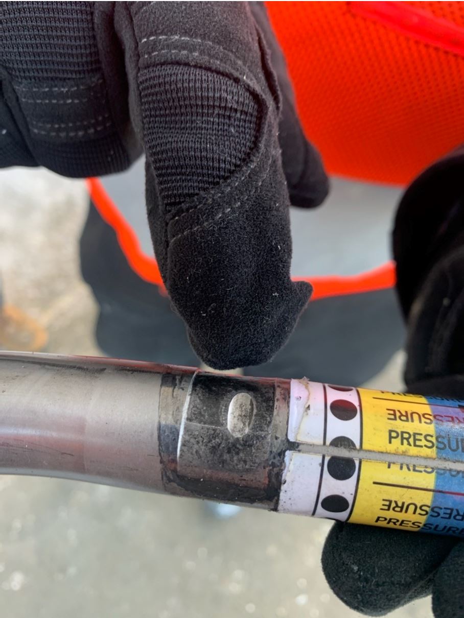
During routine maintenance of the horizontal stabilizer internal inspections, we have found the deice line that runs over top of the logo lights melted and distorted – in one case was melted right through and sealed itself shut not displaying any faults in the cockpit and no inflation of deice boots on tail-let. We have replaced line with superseded Part Number 131823PT6.
Transport Canada Comments:
According to the submitter, the flight crew did not receive any fault indications. However, it is important to note that in single or manual mode, the tail deice annunciator may appear to be illuminated normally, giving a false impression of a normal inflation-deflation cycle to the flight crew. Additionally, the instrument panel pneumatic pressure gauge may seem to indicate normal function even if there is a blockage or restriction in the stabilon, stabilizer, or tail-let deice boot line downstream of the tail pressure switch. Despite this, during surface deice operational checks, any insufficient boot inflation or deflation should be investigated further.
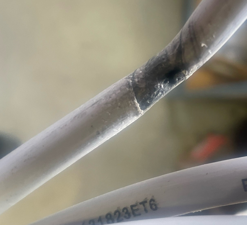
Picture 1 – Melted deice line
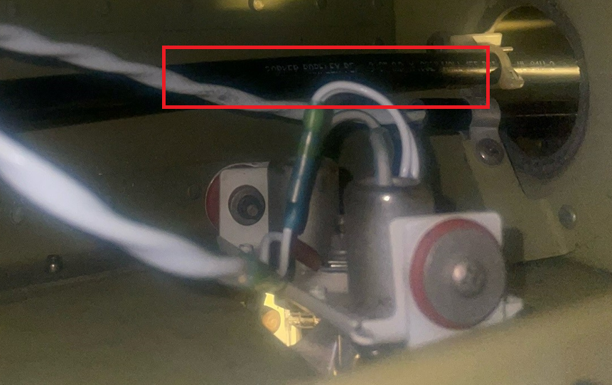
Picture 2 – Location of concern above logo light, internal of stabilizer
A100 - Aging Aircraft – Electrical Cables and Connections
SDR #: 20230210018
Subject:
During a training flight, the crew selected the landing gear handle to the up position. The landing gear did not retract. Upon checking the circuit breakers, it was found that the right-hand no 1 and no 2 subpanel feeder 50-amp circuit breakers were out, which caused loss of power to the no 2 dual fed subpanel bus. During an inspection, it was found that the zero-gauge wires, connected to the terminal studs of the isolation limiters on the isolation limiter bus, were loose and had arced. The system was repaired and the aircraft returned to service with no subsequent issues.
Transport Canada Comments:
Aging aircraft, particularly their electrical cables and connections, are a significant concern in the aviation industry. The electrical system of an aircraft is complex, and it is critical to the safe operation of the aircraft. Over time, the cables and connections in the electrical system can deteriorate due to factors such as environmental exposure, vibration, and mechanical stress. As a result, it is essential to inspect the electrical cables and connections regularly to ensure that they are in good condition and functioning correctly.
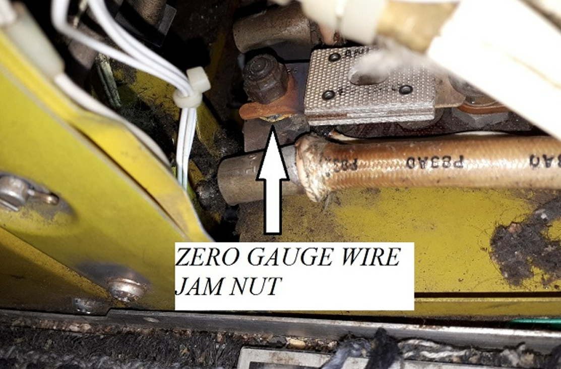
Picture 1 – Isolation limiter terminal stud location
Picture 2 – Unserviceable hardware evident
B300 - Lower Forward Wing Attachment Bolt Corrosion
SDR #: 20220808014
Subject:
During an inspection of a lower forward wing attach bolt carried out every 60 months in accordance with Beechcraft Special Inspection 57-18-03, the bolt was found to be seized and unable to be removed in accordance with Beechcraft instructions. When communicating with Beech, we were informed that this is unusual and the bolt should not be seized.
Transport Canada Comments:
A Textron technician assisted the operator in the removal and replacement of the lower forward wing attachment bolt which was seized due to corrosion. The technician mentioned that a possible cause of corrosion may be due to the use of anti-ice solution used in northern climates.
Corrosion discovered in the case of this Service Difficulty Report (SDR) has not been determined to be the result of a lack of corrosion preventative compound (CPC), although Transport Canada Civil Aviation (TCCA) would like to remind maintainers of the importance to follow recommended practices outlined in the appropriate instructions for continued airworthiness (ICA). Current mandatory replacement of the lower forward wing attachment bolts every five (5) years and annual servicing recommendations both require the correct application of specified CPC. TCCA would appreciate receiving any additional SDRs of wing attachment bolt corrosion, particularly where recommended servicing has been followed.
Since the drafting of this Feedback Article, Textron Aviation published Multi-Engine Turboprop Communiqué MP-TP-0033 (January 2023) discussing this subject in detail. Additionally, MP-TP-0033 includes recommended removal techniques to complement existing ICA maintenance practices.

Figure 1 – Forward lower wing attachment bolt – Corrosion evident

Figure 2 – Forward lower wing attachment fitting
B300 - Air Intake Anti-Ice Lip – Weld Assembly Engine Air Inlet Cracked
SDR #: 20221026012
Subject:
During regular maintenance, maintenance personnel noticed that the bottom of the engine was covered with soot. Further investigation revealed that the lower cowl inlet duct was completely broken, shooting hot bleed air directly on engine oil lines and engine wiring. Wiring was inspected, no damage was found, and the oil lines were replaced proactively. This Service Difficulty Report (SDR) is the result of investigation following a recent event. Refer to SDRs 20221019001 and 20221026010.
Transport Canada Comments:
Similar failures have also been reported on other King Air models (not limited to King Air 300 Series aircraft) that utilize an inlet de-ice lip heated by exhaust gas from a collector in the exhaust stack. Failures include weld failure of the inlet/outlet tubes as depicted below, anti-ice flex hose failure, or connection points failure. Flight crews may be unaware that the air intake anti-ice lip heating function is degraded or completely unavailable as there are no shutoff, caution, or temperature indications for this system.
Operators and maintainers are reminded to remain vigilant when inspecting the surrounding areas. Soot is an obvious sign of exhaust gas leakage which should warrant a closer look to determine the exact cause. See Feedback Issue 3/2003 for related information.

Picture 1 – Soot, signs of exhaust gas leakage

Picture 2 – Approximate location of weld failure

Picture 3 – Weld failure, source of exhaust gas leakage
1900D Incorrect Fuel Filter Assembly Leading to Low Pressure Condition
SDR #: 20211127002
Subject:
During flight, the L FUEL PRES LO annunciator came on, so the pilot turned on the standby pump, but the light did not extinguish. The airframe fuel filters were inspected, and the red (bypass) indication poppers were not popped though both filters were full of ice. The left-hand (LH) filter discs were severely deformed and bulged.
Further investigation determined that the incorrect part number airframe filter assembly was installed on the LH side of the aircraft. A right-hand (RH) filter assembly was installed on the LH side prior to the aircraft joining our fleet.
Transport Canada Comments:
The maintenance error went unnoticed until ice buildup in the fuel filter assembly installed on the LH side significantly reduced the fuel pressure, resulting in a warning annunciation. Fuel bypass would not be possible as the direction of flow (IN/OUT) was the opposite than intended. The fuel filtering function would also flow in the opposite direction than designed; outwards versus inwards of each disc.
Unfortunately, it is possible to install an opposite filter assembly (LH instead of RH) and it may not be obvious on a post-installation leak check or ground run. Fuel pressure indication will continue to function, although without a functioning fuel filter bypass, ice build-up within the filter assembly can restrict fuel flow with consequences possibly being fuel starvation.
Please note that the IN/OUT markings on the fuel filter assembly casting are not visible when viewing through the under-wing filter access door as they are located on the top side of the casting inlet and outlet ports. The upper access panel on the top of the wing may need to be removed to see the markings on the casting.

Figure 1 – Bulged filter disc due to the fuel flowing in the opposite direction than designed

Figure 2 – View through under-wing filter access door

Figure 3 – View from upper access panel with OUT marking evident
A100 - King Air Horizontal Stabilizer Bracket Cracked
SDR #: 20210917031
Subject:
During routine inspection, the bracket between the horizontal stabilizer, fuselage, and vertical stabilizer was found cracked. This may have been caused by a screw from the tail cone coming into contact with the bracket, causing a stress riser.
Transport Canada Comments:
In addition to the safety message related to the same topic in Feedback publication Issue 1/2015 shown below, care must be taken when installing the tail cone of these aircraft. In at least three (3) cases, damage to the horizontal stabilizer bracket resulting in a crack had been caused by the use of improper hardware when installing the tail cone. Similar findings have also been reported on model 99 series aircraft.
Feedback Issue 1/2015 – King Air Stabilizer Bracket Cracked
“As aeroplanes age, it is important to take your time to properly inspect all areas in order to find damage that could progress to a failure of the part. Proper lighting is important so that you can see what you are inspecting.”
The pictures below, taken of two separate aircraft, depict both left-hand and right-hand brackets cracked in the same location.

Picture 1 – Left-hand horizontal stabilizer bracket crack

Picture 2 – Right-hand horizontal stabilizer bracket crack
B200 - Engine Fuel Purge Tank Failure
SDR #: 20201026014
Subject:
During a Phase 3 Inspection on a King Air B200, it was noted that the #1 engine purge tank was damaged. The side wall of the purge tank separated at the weld and departed from the purge tank.
Transport Canada Comments:
Beechcraft King Air B200 and B300 operators that have experienced this failure in service, have described it as “smoking exhaust at shut-down” or “jet fuel odor in the environmental system that dissipates”. Fuel purge tank inspection is covered through regular intervals as outlined in the applicable Instructions for Continued Airworthiness (ICA). Particular attention should be given to the welded end caps.
Fuel purge systems installed in model 1900/C/D Airliner and King Air C90/C90A, E90 and F90 models using the same purge tank assembly, have not reported failures of this nature at this time.

Figure 1: Fuel Purge Tank Separated End Cap
B300C – Bent Rudder Horn Attachment Bolt
SDR #: 20190925006
Subject:
The B300C aircraft was undergoing a scheduled Phase 4 Inspection. During this inspection, maintenance discovered that the rudder horn assembly part number (P/N) 101-524059-1 rudder bearing bolt P/N AN175-20A was bent and the pivot bearing P/N MS28913-5C was seized and corroded. Given the fact that several examples of this type of damage was discovered in the past on the King Air fleet, the operator decided to create an in-house inspection of the rudder horn assembly that would be carried out in conjunction with the Phase 4 Inspection. No inspection of this nature could be found in the Beech program. As well, this bolt and bearing does not have a scheduled lubrication interval. The bearing is a sealed unit. An inspection of the surrounding area was carried out and the bolt and bearing will be replaced with a serviceable unit. The operator believes that the bent bolt is a result of the rudder lock not being applied on the ground during high winds.
Transport Canada Comments:
Beechcraft King Air F90, 200, 300 and B300 series aircraft share this design and Textron Aviation published Model Communique KA-2015-01 in March 2015 describing this scenario. KA-2015-01 recommends the inspection of bolt P/N AN175-20A any time the rudder is removed. Transport Canada Civil Aviation (TCCA) recommends the use of a rudder lock as noted by the submitter of the Service Difficulty Report (SDR), and that particular attention be given to this area whenever possible.

Pic#1 – Lower rudder attach bolt P/N AN175-20A

Pic#2 – Lower rudder attach bolt location
B200GT – Missing Nut at Elevator Bellcrank
SDR #: 20190807006
Subject:
While conducting a Phase 4 Inspection on the empennage section of a B200 aircraft, one of the engineers opened a button size cover (approximately 1 and a half inch diameter) to have a look at the elevator bellcrank. After removing the cover, he found that there was no nut or washer on the end of the bolt that attaches the elevator bellcrank to the vertical stabilizer. Upon review of the Phase 4 Inspection and vertical stabilizer inspection for B200 aircraft, we realized that the cover to gain access to the bolt and nut for the elevator bellcrank system is never required to be opened during an inspection. The engineer doing the inspection took it upon himself to open up the cover to see what was inside and that is how he made the discovery of the missing nut and washer. Due to the fact that this is a new aircraft and the cover had not been removed since it was delivered to us, it would seem that the aircraft had this defect since it was manufactured. We have contacted Textron Aviation and informed them of our findings, a new washer and nut were installed on the bolt and the aircraft was returned to service.
Transport Canada Comments:
Transport Canada has contacted the responsible foreign airworthiness authority. The authority is currently investigating this issue but has not identified any other aircraft with this condition in the factory and do not have any indication of this happening on other aircraft.
Transport Canada reminds maintainers and operators that this incident exemplifies the need to remain vigilant, human factor errors do not discriminate between new or old aircraft.

Pic #1 Elevator bellcrank hardware location

Pic #2 Missing nut and washer
Beech B300 – Aileron Balance Weight Cracked and Separated
SDR #: 20181023015
Subject:
Minor edits have been made to the text below taken from the Service Difficulty Report’s Problem Description. Transport Canada Civil Aviation reserves the right to edit for spelling, grammar and punctuation to increase comprehension.
During unscheduled maintenance, abnormal noise was heard coming from the right-hand aileron. Removed aileron and found aileron balance weight broken into 2 pieces. Outboard 13 inches of balance weight was found to be held on with 1 CherryMAX rivet which it was rotating on.
Transport Canada Comments:
It is important to note, flutter is a phenomenon that can occur when an aerodynamic surface begins vibrating. This can lead to failure of the control surface.
Other factors that could cause or contribute to control surface flutter:
- Improper tension on control cables
- Improper attachment security
- Balance out of limits
- Any other loose condition in the empennage
The addition of a loose aileron balance / nose weight dampener could contribute to this type of situation.
Pilots and maintainers are reminded of the importance of a thorough pre-flight inspection.

Example of a B300 Cracked Aileron Weight
A100 - Rudder Pedal Failure
SDR #: 20130325018
Subject:
Minor edits have been made to the text below taken from the Service Difficulty Report’s Problem Description. Transport Canada Civil Aviation reserves the right to edit for spelling, grammar and punctuation to increase comprehension.
Pilot reported that the aircraft was hard to steer. Maintenance found the pilot’s right-hand rudder pedal arm had broken off where the pedal is attached to the arm.
Transport Canada Comments:
This rudder pedal design is common across multiple Beechcraft models. Part Numbers (P/N) 50-524326 (all dash numbers) and P/N 002-524020 (all dash numbers). Beechcraft does include detailed inspection criteria and possible bushing insert repair instructions. Multiple Service Difficulty Reports (SDRs) continue to be submitted regarding excessive wear or failure of the rudder pedal.
Transport Canada Civil Aviation (TCCA) recommends particular attention be given during scheduled inspection. Wear may be difficult to estimate or cracks may go unnoticed while the pedals are still attached.
Related Feedback Article 1/2014 (SDR) # 20120510005

Failure of the rudder pedal arm at the brake pedal pivot holes.
B100 - Smoke in the Cabin
SDR #: 20190516012
Subject:
The translated article below is taken from a Service Difficulty Report’s (SDR) problem description submitted in French.
During the initial climb, the pilot felt it was unusually hot even though the heating system was set correctly. Shortly after, smoke began flowing from the exhaust tubes. The pilot declared an emergency and returned to the airport of departure where it landed safely. The maintenance team investigated and found a melted heating duct. The aircraft is still on the ground so that the cause of the overheating can be investigated. The King Air B100 has no system to indicate overheating of its heating system. An inspector from the Transportation Safety Board (TSB) came to report on the situation. Two heating ducts (part number (P/N) 97-555011-15) were replaced, the right-hand bypass valve was found to be non-functional, which caused the overheating. The bypass valve actuator (P/N NYLC9871) was replaced, the system was ground-checked and operates normally. The aeroplane was returned to service, and it flew. The system is functioning normally.
Transport Canada Comments:
Similarities exist between this event and a B100 Emergency Landing in 2012. Both aircraft experienced smoke in the cabin due to melting of a section of hot air duct below the floor. See TSB Aviation Investigation Report A12Q0029.
Beech King Air 90 and 100 series aircraft do not utilize a duct overheat annunciator. Repeated overheating of the system, environmental exposure to heat (proximity to bleed lines), or other unreported anomalies relating to the bleed air and heating system, can all exacerbate the problem. A faulty bypass valve in this case could introduce air hot enough to cause damage to air ducts.
Maintenance personnel are reminded to pay particular attention to the hot air ducts and under-floor bleed air lines. The ducts are covered with insulation, and it could be difficult to detect any thermal deterioration or deformation. Beech recommends to physically inspect ducts by touching ducts, checking for thermal deterioration, deformation of the ducts, and proper connection at the joints.
Caution: Bleed air lines as well as hot air ducts may run in proximity to pneumatic de-icer boot pressure tubes (Ethyl vinyl Acetate (EVA) tubing) and electrical wiring. Minimum distances as identified in the Maintenance Manual must not be overlooked.
Deformed ducts or EVA tubing should always warrant further investigation to uncover the cause.

Melted cabin heater duct
A100 - External Power Terminal Strip
SDR # 20160128002
Subject:
Original Submission:
While completing Airworthiness Directive CF-1981-25R6, it was noted after removing the wing panel inboard of the right-hand (RH) nacelle that 2 wires, (P83D0 and P83B0) were disconnected from the external power terminal strip. The wires had made contact with the wing spar and, by arcing, had burned a hole in it. A fleet inspection was carried out with no other defect found. Upon further investigation, it was determined that the cables must have been removed during a previous maintenance action. The area was thoroughly inspected and neither the washer nor the nut was found in the area. Also, by the condition of the stud (dirty) it was determined that the cables must have been off for quite a long time. The operator reviewed almost 2 ears of maintenance records and did not find any evidence of maintenance carried out in the area that would have required removing those cables. The operator suspected that the cables had been removed during the last heavy check visit of the aeroplane. The operator indicated that it was to discuss the situation with its heavy maintenance service provider and that it intended to bring it to the attention of its maintenance employees during recurrent training.
Transport Canada Comments:
Despite the best efforts of Transport Canada and the industry to educate and prevent human factor incidents from occurring, these types of maintenance errors continue to happen. This was a very avoidable and costly mistake and it could have turned out much worse.
Maintainers are reminded to be extra diligent when carrying out maintenance activities to make sure that any component or system that is disturbed is returned to its normal configuration or condition before closing up. In addition, taking simple precautions and best practices like recording any items that have been disturbed in the maintenance records, tagging disturbed wires or lines with streamers or flags and having good panel or zone close out inspection procedures could have caught the error before it became a mishap.

External Power cables disconnected at Terminal Strip
BOEING
B737-800 – Main Landing Gear (MLG) aft trunnion pin
SDR #20251002022
Subject:
During the investigation of a recent MLG collapse of a B737-800 aircraft, it was discovered that a fractured MLG aft trunnion pin had failed. Following the event, during a proactive campaign to replace left and right MLG aft trunnion pins, an additional defective pin was found. The right MLG aft trunnion pin on a second aircraft was found with defects and exhibited plating cracking; Refer to Figure 1 below. The trunnion pin was sent to the Transportation Safety Board (TSB) lab for further investigation. The aft trunnion pin life limit is 75 000 Flight Cycles (FC) and restoration/overhaul is at 21 000 FC or 10 years.
The subject aft trunnion pin times since new were:
Date: 02/10/2008
Time Since New (TSN): 57 791 Flight Hours (FH)
Cycle Since New (CSN): 19 198 FC
Time since last restoration/overhaul:
Date: 04/06/2018
Time Since Overhaul (TSO): 20 721 FH
Cycle Since Overhaul (CSO): 7667 FC
Transport Canada Comments:
The aft trunnion pin that was found damaged, and the one that failed upon landing, had been in service since early 2009 and accumulated 19 198 FC and 17 920 FC of total time respectively. Both pins had been through one overhaul and the times at overhaul were 11 531 FC and 9142 FC at the 10-year calendar overhaul limit. The Federal Aviation Administration (FAA) issued an Airworthiness Directive (AD) US2016-18-01 mandating a Service Bulletin (SB) 737-32-1448R1 and later superseded it with AD US2019-01-03 mandating SB737-32-1448R2 for MLG - forward and aft trunnion pin assemblies inspection and change, due to previously found corrosion and cracking issues. The operator had complied with the ADs and SB requirements and had upgraded the pins to the latest part number.
The Transport Canada Civil Aviation (TCCA) is aware of two National Transportation Safety Board (NTSB) reports. One from August 2023 on a 15-year-old aircraft, and one in December 2019 on a 9-year-old aircraft, which describes MLG aft trunnion pin failures occurring at 15 826 FC and 23 535 FC. The August 2023 report noted one overhaul of the pin and cracking had occurred at least 797 FC before failure. The December 2019 report noted two overhauls of the pin and cracking occurred at least 6225 FC before failure. This means the pins in these two earlier events started cracking at 15 029 FC and 17 300 FC since new.
Please be aware that MLG aft trunnion pins have failed in the range of 15 029 to 19 198 FC since new on some aircraft. This is well in advance of the published 75 000-cycle life limit or in some cases even the overhaul interval of 21 000 FC. The investigation of this event is still ongoing at this time.

Figure 1 - Corrosion pitting on aft trunnion pin
767 375 – B767-300 - Cargo Loading Pallet Handling System Wiring Burnt
SDR #: 20210803013
Subject:
During routine maintenance, it was found that multiple drive units in the aft lower cargo bay were not working. Troubleshooting found multiple (2) circuit breakers popped. Further investigation discovered burnt wires between fuselage stations FS.1142 and FS.1197. The burnt wires were repaired in accordance with the Supplementary Wiring Procedures Manual (SWPM), the cargo loading pallet handling system was checked in accordance with the Aircraft Maintenance Manual (AMM), and the aircraft was returned to service.
Transport Canada Comments:
The cargo loading pallet handling system was installed along with the cargo system installation when this aircraft was reconfigured from passenger to freight in accordance with a Supplementary Type Certificate (STC). In the photos provided, the wiring installation appears to be proper, but there are damaged wires and signs of overheating that should not be occurring. The operator would have performed an assessment to understand how and why this event occurred to prevent any re-occurrence and will likely be inspecting other aircraft in their fleet with this same STC installation.

Figure 1: Location of damaged wires

Figure 2: Closeup of the damaged wires
767 306 – B767 – Carbon Brake Failures/Premature Wear-Out
SDR #: 20190814013, 20190822011, 20190903016
Subject:
The following three service difficulty report (SDR) descriptions were provided by the same operator and additional reports have also been received.
- During the daily service check, the #6 brake rotor segment was found fractured, 1/2 the inner disk was missing. The operator will request a bench report from the brake overhaul facility as there is a known brake oxidation issue (refer to Boeing Service Letter 767-SL-32-106). This issue was addressed with an improved heat stack. The heat stack that failed on this brake was the improved heat stack installed at the last overhaul.
- During a service check, maintenance discovered oxidation of the #4 carbon brake and replaced it. The service letter provided in 2009 by Boeing, identifies an Aircraft Maintenance Manual (AMM) revision for the inspection requirements to identify the issue, and although there is an inspection in place, it only identifies the issue and does not correct it.
- During a service check, the #8 brake was found with oxidization on the heat sink kit. The #8 brake was replaced and the aircraft returned to service.
Transport Canada Comments:
Boeing issued Service Letter 767-SL-32-106 regarding the Effects of Alkali Metal (Organic Salt) Runway Deicers on Carbon Brakes and is applicable to all aircraft models with carbon brakes. This service letter informs operators of reported events of catalytic oxidation of carbon brake disks. The oxidation is a result of the exposure to the alkali metal (organic salts) used mainly in potassium acetate, potassium formate, sodium acetate, and sodium formate runway deicers.
The following information has been excerpted from Boeing Service Letter 767-SL-32-106: “In some cases, when a carbon disk is contaminated with runway deicer, the anti-oxidation coating applied by the brake manufacturers to protect the carbon disks is compromised, allowing catalytic oxidation of the carbon disk. The catalytic oxidation occurs when the carbon disk’s temperature is elevated to normal or higher brake-operating temperatures with a compromised anti-oxidation coating. The alkali metal catalytic deposits react with oxygen and the carbon material, resulting in the loss of mass through an oxygen-transfer mechanism, leading to the structural degradation of the carbon disk over time. The structural degradation rate is dependent on the amount of contamination and the time the carbon disk remains at an elevated temperature. This results in damaged carbon disks, piston impressions in the pressure plate, missing rotor lugs, chipping or flaking of the carbon. If allowed to continue these defects will manifest into a structural failure of the pressure plate, rotor disks or stator and cause damage to the wheel assembly.”
From 2017 to April 2021, Transport Canada received 30 reports of carbon brake failures on the B767 model aircraft. The average failure time in-service from these reports was 3569 hours and 1537 cycles, and the reports came largely from one operator. Transport Canada reviewed the issue with other operators of the B767 aircraft, and found that they had experienced similar issues with carbon brake oxidation.
Operators reported that, even though the Original Equipment Manufacturer (OEM) had addressed the situation with improved coatings, they continued to experience related failures. As a result, they elected to replace the carbon brakes on their aircraft with steel brakes, which are not susceptible to this type of failure.

Figure 1 - Oxidation damage on stator disk, outside edge

Figure 2 – Oxidation damage on rotor

Figure 3 – Oxidation damage on rotor drive clip, outside edge

Figure 4 – Oxidation damage on stator drive lugs, inside diameter

Figure 5 – Oxidation damage on a stator or pressure plate showing piston impressions
737 2T2C - B737-200C – Aft Passenger Door and Airstairs Hinge Breaks
SDR #: 20190808001
Subject:
The aircraft was on the ground and the flight attendants called for the closure of the main cabin door. While closing the main cabin door, as the airstairs were rising, the forward hinge fitting broke allowing the airstairs and door assembly to fall down. When the door assembly swung down, it punctured the lower fuselage in a few places.
Transport Canada Comments:
No follow up or lab reports were provided for the broken hinge fitting nor was time in-service provided. The hinge fitting was likely in-service for some time and the airstairs are used regularly, so fatigue would be a reasonable assumption for such a failure. It’s possible that there may have been some pre-existing damage in the form of a dent or a crack, however confirmation is not possible without a detailed inspection of the broken fitting or a lab report.
These fittings go through many cycles of use in regular service and are subject to high loading as they support both the weight of the door and the airstairs. Regular detailed inspections and replacement of fittings that exhibit damage, is the best way to help prevent similar occurrences.

Fig 1: Illustrated Parts Catalog showing fitting location

Fig 2: Illustrated Parts Catalog detail of broken fitting

Fig 3: Broken fitting lower section

Fig 4: Broken fitting upper section

Fig 5: Damage to lower fuselage

Fig 6: Broken fitting close up
737 86J - Burnt out Logo Light
SDR #: 20190107009
Subject:
Minor edits have been made to the text below taken from the Service Difficulty Report’s Problem Description. Transport Canada Civil Aviation reserves the right to edit for spelling, grammar and punctuation to increase comprehension.
Intermittent Flight Data Recorder (FDR) light caused by burnt Logo Light connector and receptacle. Extensive troubleshooting found that the FDR fault only happens when the Logo Light is turned to on position. Horizontal stab connector D40190 was checked and found that the receptacle and the connector were toast.
The following parts were replaced and no further occurrences were reported: Connector Part Number (P/N) : BACC63BP14C12SN, receptacle P/N: BACC63BV14F12PN
Transport Canada Comments:
As maintenance personnel, additional consideration must also be given to the operating environments that may cause early buildup of corrosion. Electrical connectors and receptacles often hide the defect until the unit arcs and creates a fault. Please follow your aircraft’s corrosion prevention and control program for appropriate methods to avoid such a snag.

Pic 1: Evidence of arcing and soot on the connector pins

Pic 2: Melted receptacle
737 8 - Leaky Line
SDR #: 20190225014
Subject:
Minor edits have been made to the text below taken from the Service Difficulty Report’s Problem Description. Transport Canada Civil Aviation reserves the right to edit for spelling, grammar and punctuation to increase comprehension.
Maintenance found system “A” hydraulic quantity at 60%. Upon inspection, fluid was found leaking from the #1 engine aft fairing drain tube at a rate of approx. 4 drops/sec. Hydraulic supply line was found chafed from contact with the aft strut fairing. Hydraulic line was replaced and leak checked serviceable.
Transport Canada Comments:
Even new aircraft may have surprise leaks. When installing components or performing visual inspections, maintainers are reminded to be diligent for potential chafing between lines, conduits, hoses, electrical harnesses, structure, etc. Maintainers are also reminded to wear all the proper personnel protective equipment while working around Skydrol and all other harmful chemicals used on aircraft.

Pic 1: Location on wing of leaking line

Pic 2: Chafe mark on inner web of fairing

Pic 3: Chafe mark on line with hydraulic fluid spraying from hole
727 225 - Daily Inspection discovery
SDR #: 20180816015
Subject:
Minor edits have been made to the text below taken from the Service Difficulty Report’s Problem Description. Transport Canada Civil Aviation reserves the right to edit for spelling, grammar and punctuation to increase comprehension.
During a daily inspection of the aircraft, a hydraulic leak was found in the aft airstair area. Closer investigation found the hydraulic "a" system elevator module had split. The failure occurred at the attach point of the valve assembly motor to the body of the modular package. The modular package assembly was replaced and the aircraft returned to service.
Transport Canada Comments:
Aging aircraft provide unique defects possibilities. Maintainers should be extra vigilant during daily inspections and other scheduled maintenance activities. The total time for the part on the aircraft was 43.9 hours and 26 cycles. The part condition of the assembly when purchased and installed was “Inspected”.

Picture 1: Module assembly showing missing valve

Picture 2: Valve found hanging beside module assembly
737 4Q8 - Missing Cotter Pins
SDR #: 20170822024
Subject:
Minor edits have been made to the text below taken from the Service Difficulty Report’s Problem Description. Transport Canada Civil Aviation reserves the right to edit for spelling, grammar and punctuation to increase comprehension.
During routine maintenance of the flap system, it was discovered that the two bolts that attach the right hand fore flap to the fore flap sequencing carriage assembly were missing. The flap was being retained by the two attachment bushings (69-43503-1 and 69-43503-2) that remained connected to the brackets on the fore flap and the carriage fittings and the links to the mid flap.
The bolts (BACB30LJ5D12 or BACB30NR5DK12), washers (AN960PD516) and nuts (BACN10JD105) were found in the respective canoe fairings at Wing But Line 254 and 355. The cotter pins (MS24665-304) were not found.
Transport Canada Comments:
In accordance with the Canadian Aviation Regulations, Standard 571.10 (4), Types of work table, (d) Work that disturbs engine or flight controls:
That the system has been inspected for correct assembly and correct locking of any parts disturbed by the maintenance performed, including an operational check for proper sense and range of motion of the engine or flight controls has been accomplished, by at least two persons, and the technical record contains the signatures of both persons.
(amended 2010/12/30)
Information Note:
One of the signatures required by this section may be that of the person who has signed the maintenance release.
Although the omission of the cotter pins did not end up causing an incident, the bushing could have migrated out of the fittings causing the loss of the flap assembly. Maintainers can institute a dual inspection system for all work performed. It never hurts to get a second look.

Pic 1: Bolt and nut found in flap canoe

Pic 2: Bushing remains in fitting holding flap in place

Pic 3: Bushing in fitting
737 8CT - Wheel assembly missing/broken tie bolts
SDR #: 20160203026
Subject:
During the take-off roll, at approximately 120 to 130 knots, the crew reported that they heard a bang followed by a vibration and decided to reject the take-off.
When maintenance arrived at the aircraft, they confirmed that the number 1 and 2 tires had blown and that damage was also found to the wheel halves. The cause of the tire blowout was unknown, but all affected components were changed out and sent to the appropriate vendor for assessment.
The number 1 and 2 wheel assembly halves were found still held together by the tie bolts. The number 1 wheel assembly had four sheared tie bolts and all the bolts appeared to be intact on the number 2 wheel assembly. The wheel fuse plugs on both wheel assemblies were inspected and found to be intact. The aircraft servicing history was reviewed and no abnormal servicing issues were noted since the installation of the wheel and tire assemblies.
All wheel assemblies and the number 1 and 2 brakes were replaced to return the aircraft to service. The service difficulty report (SDR) will be updated with all findings following vendor analysis.
Transport Canada Comments:
Investigation by the shop concluded all the bolts from this event were as follows:
- All bolts were evaluated and met specifications for hardness, coating and material (H-11 steel) with no indications of a batch or quality issues.
- The cause of the six fractured bolts was found to be fatigue. Four bolts were found with cracks initiating from the 8th to 9th thread root and two bolts were found with cracks initiating from the under-head radius transition area.
- No abnormal cause of the fatigue cracking was detected (corrosion, mechanical damage).
- Overload fractures detected on three of the six bolts were assumed to have occurred during the take-off roll.
- No indication of bolt stretch was observed.
The original equipment manufacturer (OEM) was contacted and reported that they were unaware of any problems with tie bolts in industry. The operator initiated a fleet campaign replacement of all bolts, and limited the bolts to less than the OEM recommended service life, in an effort to prevent these issues. The reduced service life program has worked and reduced the failure frequency. One SDR has been reported since July 2016 where a loose bolt was found during maintenance.

Wheel showing wheel damage and missing tie bolts

Wheel and tire damage

Photo of a sheared tie bolt showing fracture at threads
737 8Q8 - Loose metal found in brake assembly
SDR #: 20170419007
Subject:
During a gear inspection, the maintenance staff noticed the appearance of loose metal inside the aperture of the rim. After removal of the wheel and brake assembly, the brake disk retainer was found loose and metal was also seen coming from the brake disks assembly. The metal brake disk retainer had started to wear a groove in the interior of the wheel rim and a piece of metal was removed from the brake disk assembly.
Transport Canada Comments:
It was not reported what caused these defects, but both issues were discovered when maintenance personnel found something that did not look right and investigated. If the defect had not been found, more extensive and costly repairs may have been needed and aircraft braking capability would have been adversely affected.

Figures 1a and 1b - Brake disk retainer showing the wheel assembly wear (location and close up)


Figures 2a and 2b - Loose metal found inside brake assembly (where found and what it looked like

757 2B7 - Leaking Elevator Pressure Reducer By-pass Valve
SDR # 20170518018
Subject:
During a service check, the maintenance staff found a hydraulic fluid puddle beneath the tail of the aircraft. Further investigation of the leak revealed that when hydraulic system pressure was applied, a notable increase of hydraulic fluid flow was observed. The elevator pressure reducer/by-pass valve was found to be the source of the leak and was removed and replaced. After removal and upon closer inspection, the valve case was found cracked.
Transport Canada Comments:
The maintenance staff investigated something that appeared out of the ordinary, possibly preventing an in-flight failure. By finding this defect on the ground, observant maintenance staff may have prevented a failure that would have adversely affected the elevator control system and the associated hydraulic system. The leaking valve could have caused a large loss of hydraulic fluid, possibly necessitating crew emergency actions.
Alert maintenance personnel exercising awareness during maintenance activities and looking beyond the immediate task can find problems before they manifest into more serious events.

Complete valve assembly

Valve showing cracked area
767-338 - Aileron Power Control Actuator Rods Not In Safety
SDR # 20160726005
Subject:
While performing a routine lubrication, during an aircraft phase check maintenance visit, it was discovered that the right hand (R/H) inboard aileron power control actuator (PCA) input rods were not properly safety-wired at both ends of the two rod end assemblies. The deficiency was corrected by torqueing the jam nuts to the maintenance manual requirements and lock wiring the R/H inboard aileron PCA input rods. The aileron PCA rigging was not affected as it was checked and found to be within the required limits. All remaining aileron power control actuator locations were inspected on the aircraft with no discrepancies noted.
Transport Canada Comments:
The aircraft had recently undergone a heavy maintenance check and it appears that the final aileron rigging checks had not discovered the lack of proper aileron control system safety. The defects were discovered and corrected by the aircraft operator during a phase check inspection that followed the heavy check. The operator then performed a fleet campaign to ensure that all other aircraft in their fleet did not have similar problems.
The thorough and detailed inspection techniques of the aircraft operator’s maintenance staff led to the discovery of a defect that if left unnoticed could have contributed to aircraft control issues during flight.

Rod shown with loose nut and safety wire not done up properly

Loose locking nut and broken wire
BOMBARDIER
CL215 6B11 (CL415) - CL-415 External Power Receptacle Ground Lug Arcing Damage
SDR #: 20250331018
Subject:
Performing ground maintenance to do a drying run of the turbine engine after a rinse. The Ground Power Unit (GPU) was being used at the time. The aircraft electrical systems lost power, and the technician in the cockpit heard an arcing noise coming from the rear of the cabin. After inspection, traces of arcing damage were found at the ground terminal for the GPU receptacle. Troubleshooting pointed to speculation of corrosion at the ground stud and terminal connection on the frame.
Transport Canada Comments:
This service difficulty report discloses some significant damage to a fuselage side frame caused by arcing, and excessive heat of the auxiliary power receptable ground lug. The operator carried out an inspection to verify the conformity of the ground lug hardware assembly to the type design, as illustrated in the Illustrated Parts Catalogue (IPC). He further verified the tightening torque of the ground stud and the ohmic value of the bonding, as being within limits specified by the Original Equipment Manufacturer (OEM). No anomalies were found. The operator suspected the presence of corrosion at the ground terminal of the ground lug, significantly altering the bonding of the ground lug. The high amperage delivered > 700 Amperes during engine start-up caused the ground stud to overheat due to the Joule effect.
Since the side frame had substantial heat damage, the operator contacted the OEM to obtain an approved repair for the heat damage. The OEM issued a Repair Design approval (RDA) for permanent repair for the arcing damage.
Transport Canada would like to remind operators and maintainers of the necessity to be vigilant with respect to the condition of high current electrical connections like these ground studs, particularly on older aircraft and especially on aircraft subjected to amphibious operations.
Figure 1 - Traces of burning found on the ground terminal of the ground socket.
CL-600-2B16 (604) - CL605 Potable water tank electric terminals missing insulating silicone
SDR #: 20230322002
Subject:
While performing a 6-month inspection on a Challenger 605 (CL605) and working on the potable water tank, with electrical power applied to the aircraft, my colleague was electrocuted and had to go to the hospital. This happened because there is an installation work step missing to apply sealant on the electrical connections. This step was found missing from the Supplemental Maintenance Manual (SMM) work step within SMM task 21-41-57-400-801 for the CL605 aircraft.
When you compare the Challenger 650 (CL650) SMM with CL605 SMM, they are not the same. In the CL650 SMM task 21-41-07-400-801, you must apply silicone on the electrical connections and in the CL605 SMM task 21-41-57-400-801 this work step is missing. This leaves 115 volts on the un-protected electrical connections and you can easily touch them while servicing the potable water tank on the CL605. The technician working on the aircraft touched the electrical connection on the baggage compartment heater thermostat with his forearm. As soon as he touched the potable water tank with his hand, he was electrocuted. The Bombardier description reads, “…the terminals of the thermostat are located on the water tank forward access door, which is only opened by maintenance personnel during maintenance activities….” As per the engineering approved under the completion Supplemental Type Certificate (STC) SA06-90 on the CL605, there is no silicone installed on the terminals of the thermostat. Therefore, there were no errors in the SMM task 21-41-57-400-801 as it reflects the engineering approved on the aircraft. On the CL650, there is engineering coverage to install silicone on the terminals which is a safer installation.
Transport Canada Comments:
This issue was brought to Bombardier’s attention and CASA 2024-12 was published on November 21, 2024, by Transport Canada as an advisory and awareness measure. This article is to provide additional awareness to maintenance personnel who perform maintenance on the affected aircraft.
The investigation into the issue noted the following:
- The terminals of the Baggage Compartment Heater thermostat (part number 2511L1941658) are located on the water tank FWD access door, which should be only accessed by maintenance personnel during maintenance activities.
- On the CL605, as per the engineering approved under the completion STC SA06-90, there is no silicone installed on the terminals of the thermostat (Figure 1). Therefore, the Supplemental Maintenance Manual (SMM) task 21-41-57-400-801 is aligned with the approved engineering. However, it has been identified that the thermal sensor in the FWD baggage area access door can result in maintenance personnel contact with 115-volt electrical power while servicing the potable water tank.
- On the CL650, there is engineering coverage to install silicone on the terminals as per SMM task 21-41-07-400-801 (Figure 2).
As a result of the investigation, Bombardier issued a recommended Service Bulletin (SB) 605-21-006, to address the issue and install sealant on the exposed terminals and correct STC SA06-90, FAA STC ST0235NY and EASA STC 10016019. The SB was issued to all affected aircraft serial numbers to correct the original installation per the affected STCs.
It is strongly recommended that operators of all affected aircraft carry out the instructions of Bombardier recommended SB605-21-006 to prevent inadvertent injury to personnel.

Figure 1: CL605 unprotected terminals

Figure 2: CL650 with silicone protected terminals

Figure 3: Location of potable water tank thermostat
CL600 2B19 (RJ200ER) – CRJ100/200 – Fuel Feed System Corrosion and Leaks
SDR #: 20210112003
Subject:
While running the auxiliary power unit (APU), maintenance discovered a fuel leak. The investigation determined that the fuel leak was caused by severe corrosion of the APU fuel feed line. Maintenance attempted to rob a replacement fuel line from another aircraft but found that the line was also corroded at the same location. The fuel lines are to be replaced with serviceable parts.
Transport Canada Comments:
Nine (9) SDRs have been received recently for this issue which includes corroded shrouds, corroded shroud fittings, and corroded and/or leaking fuel lines. All seven (7) of the affected aircraft in the SDRs had been in service for 17 years.
This issue was the subject of an investigation by the manufacturer who concluded that these types of defects present a safety risk that is adequately addressed by existing mitigations. The investigation considered that the issue should be detected during routine operations by the daily walkaround inspections that indicates particular attention should be paid to any evidence of fluid leaks on or around the aircraft. Additionally, these defects can be found through routine maintenance such as the “below-floor” zonal inspections and the recurrent leak test requirements for the affected lines.
However, the area is still known to be susceptible to significant corrosion defects. The Illustrated Parts Manual, Section 28-20-00, Figure 5, shows the area where defects have been found, and the lines, shrouds and fittings in this area that can be affected by corrosion and develop leaks. Removal of the shroud is required to inspect and find the corrosion defects because they originate inside the shroud and on the lines.
Operators should be aware of this issue and the potential defects in this area and consider whether more frequent inspections are indicated for their operation in order to detect excessive corrosion and ensure the integrity of the lines and shrouds.
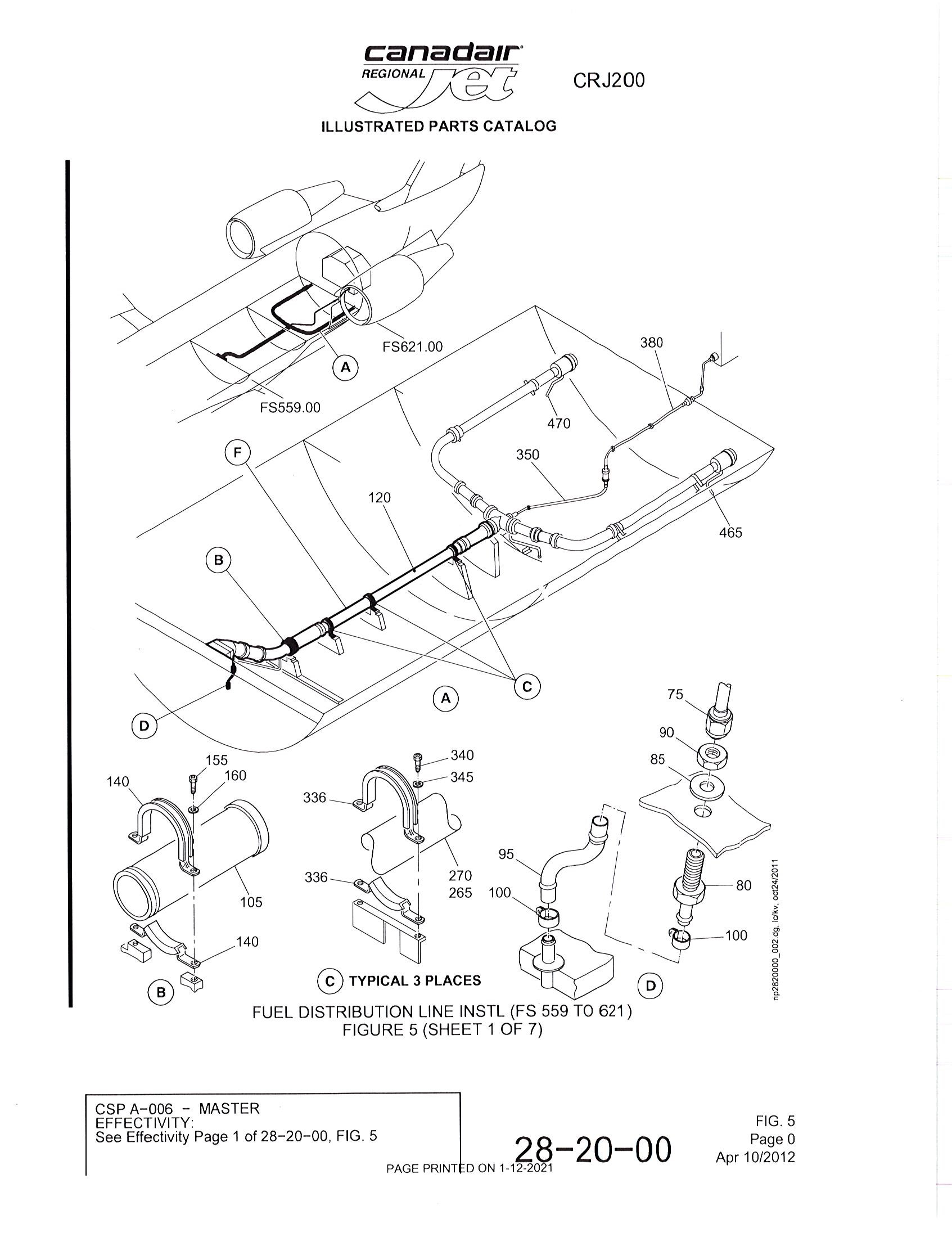
Figure 1: IPC reference showing affected area
Text on picture: Illustrated Parts Manual
Typical 3 placesFuel distribution line instl (FS 559 to 621)
Figure 5 (Sheet 1 of 7)
CSP A–006 – master
Effectivity:
See Effectivity Page 1 of 28–20–00, FIG. 5
page printed on 1-12-2021
fig. 5
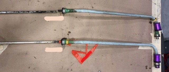
Figure 2: Lines showing corrosion
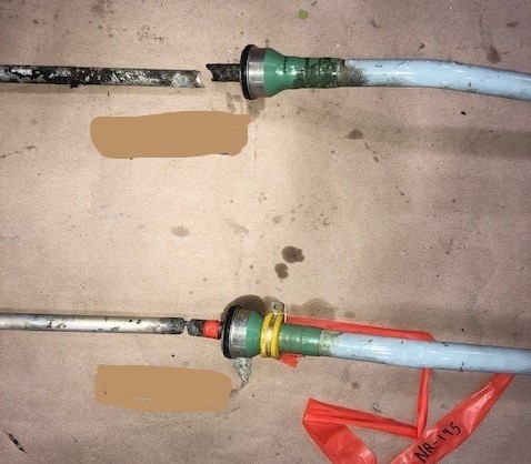
Figure 3: Broken lines close-up
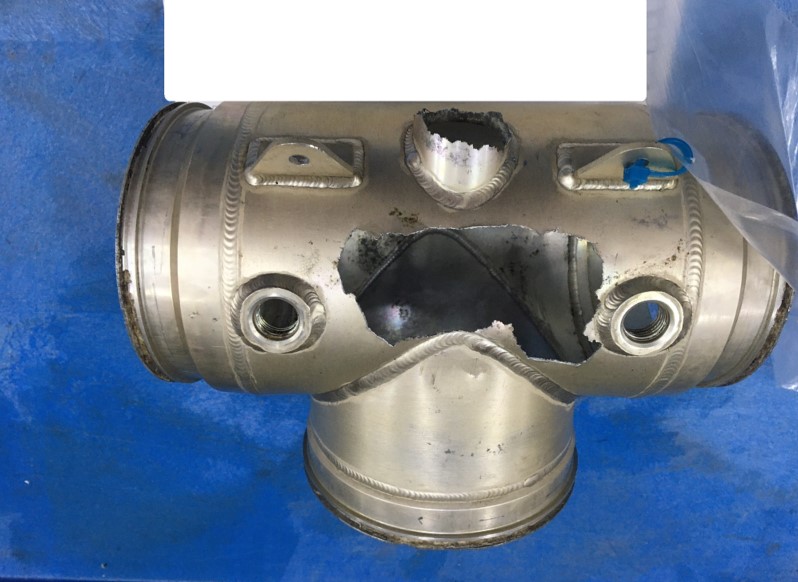
Figure 4: Corroded Tee fitting outside view
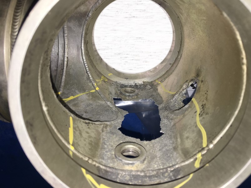
Figure 5: Corroded Tee fitting inside showing corrosion
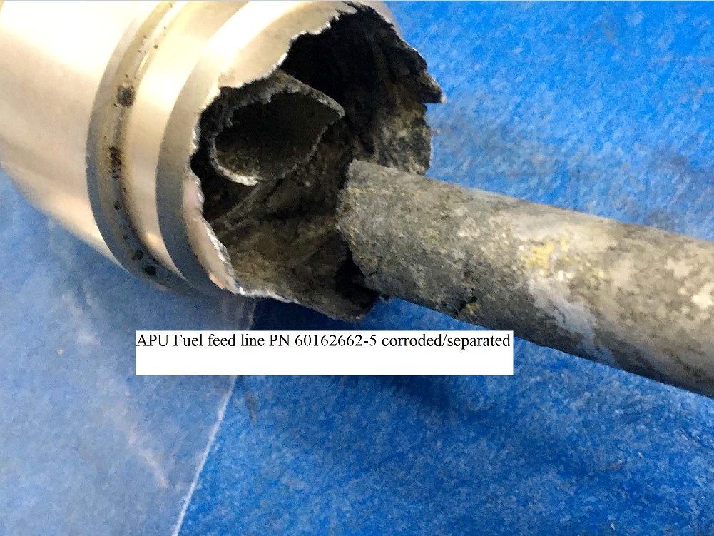
Figure 6: Close-up of corroded line break showing extent of corrosion
BD 700 1A11 – Global 5000 Unintended Life Raft Deployment
SDR #: 20190912008
Subject:
During cabin inspection the pilot observed that the life raft that is stored under the aft cabin divan appeared to be swollen and he was unable to move or remove the raft. The mooring line and ripcord are both on the inside of the compartment and were inaccessible. The ripcord/mooring line were not pulled. Something had failed and caused it to inflate. A procedure was supplied by Winslow where after trying to remove the raft by following the first steps in the procedure it was unsuccessful. The procedure for drilling the raft in the location was followed and it was found that the raft was inflated; the pressure was released and the raft was successfully removed from the aircraft. It was found to have self-inflated with both the inflation pull handle and mooring line still intact and not pulled.
Transport Canada Comments:
It is important to inspect all safety equipment before flight to ensure that they are in proper working order. In this case, the life raft would have been unusable in an emergency situation.

Picture 1 – Image of the inflated life raft
CL600 2C10 (RJ700) - CRJ 702 – Aileron Power Control Unit Attach Lug Broken
SDR #: 20200818014
Subject:
After the aircraft arrived, it was noted that the right aileron power control unit (PCU) lug was broken off. The flight crew didn't mention that anything was abnormal in flight and no logbook entry was made. The defect was found on a maintenance walkaround.
The manufacturer was contacted, and the right aileron was replaced in accordance with Aircraft Maintenance Manual (AMM) task 27-15-01-400-801. Due to the nature of the defect, the manufacturer also requested the following inspections and maintenance actions be completed prior to returning the aircraft to service:
- Perform a detailed inspection of the right aileron hinge fittings assembly in the wing per AMM task 57-61-27-220-801 and perform the same inspection on the left wing for the left aileron. If the left aileron is not removed, move the surface upward for access to inspect the wing hinge fittings.
- Perform a detailed inspection of both right aileron PCUs per AMM task 27-14-01-220-801.
- Do a functional test of the right aileron PCUs per AMM task 27-14-01-720-802.
- Perform rigging of both left and right aileron PCUs per AMM task 27-14-01-820-801.
- Carry out a functional check (backlash) of the aileron control system per AMM task 27-11-00-720-803 on both left and right ailerons.
Transport Canada Comments:
Due to the nature of the defect and the unknown cause, the manufacturer requested additional tasks be performed after replacing the broken aileron fitting to ensure proper system installation and function. It is good practice to consult the manufacturer when defects of this type are discovered in case additional checks are recommended prior to returning the aircraft to service.

Figure 1: Right aileron showing broken lug from outboard PCU

Figure 2: Closeup of aileron PCU fittings

Figure 3: Closeup of broken lug
CL600 2C10 - RJ700 - Bleed Air Supply Duct Cracked at Welded Flange
SDR #: 20200110007
Subject:
The left-hand (LH) side bleed air supply duct that passes through the aft pressure bulkhead was found cracked at the welded flange on the aft side of the bulkhead.
Transport Canada Comments:
The submitted Service Difficulty Report (SDR) did not discuss how this defect was found, but it should be noted that the area is fairly difficult to access and inspect. Being aware that defects have been found in this location may help maintainers when troubleshooting snags or looking for defects during scheduled inspections.

Figure 1: LH bleed air supply duct leak location

Figure 2: Duct cracked flange shown
CL600 2D24 (RJ900) - Passenger Door Structure Found with Level 2 Corrosion
SDR #: 20190930017
Subject:
During scheduled maintenance, level 2 corrosion damage beyond allowable limits was observed on the forward former of the passenger door assembly at fuselage station (FS) 317. The damaged area was cut out and replaced with a new section of former, and the repair work was accomplished in accordance with approved repair engineering order (REO) 690-52-11-582.
Transport Canada Comments:
The passenger door serves as the main entrance stairs to board and deplane the aircraft. It is often open to the elements and is subject to snow, ice, rainwater and many compounds that can be deposited by passenger footwear when using the stairs. This makes it an area that requires frequent inspections, frequent cleaning and recurring applications of corrosion inhibiting compounds (CIC) to prevent corrosion.
Transport Canada is not aware of the actual inspection interval frequency for this task for this operator. The service difficulty report did not indicate that a localized corrosive spill caused the corrosion, so this finding of level 2 corrosion suggests a more frequent inspection interval is likely needed and should be applied to this area.


DHC 8 400 - Dash-8-400 Broken Aileron Cable
SDR #: 20191115007
Subject:
After takeoff, the control column was showing a right turn even when in level, zero degree bank. All other indications were normal, including trims. All spoilers were down as normal. Autopilot continued to be functional. The crew radioed to maintenance control, who advised the crew to fly straight and level, and 45 degrees of yoke was required. The crew then proceeded to declare a pan pan and divert to the nearest airport. The aircraft landed without incident. On initial inspection, one aileron’s trailing edge is up. A snapped cable is suspected.
Transport Canada Comments:
The aileron cable broke at a pulley on the wing trailing edge. This appears to be a maintenance related problem since the cable broke before maintenance found the worn cable during a scheduled inspection. Due to the redundancy built into the flight control system in this aircraft, the broken cable did not affect the safety of the flight, however on some other aircraft the results could have been more dire. During cable inspections, maintenance staff are reminded to inspect the complete length of the cable in the area being inspected to detect broken strands, seized pulleys, loose cable tensions or any other problems that could interfere with the flight control system.

Broken aileron cable
CL600 2B19 (RJ200) - RJ200 Gear Down Disagree due to Broken Nose Gear Door Spring Bracket
SDR #: 20180913013
Subject:
During the approach, the gear disagree message appeared on the engine-indicating and crew-alerting system (EICAS) accompanied by the EICAS Display 1, an indication that the nose landing gear (NLG) was not in the down and locked position. The Quick Reference Handbook (QRH) was applied and a manual landing gear extension was accomplished. Upon inspection, the NLG door spring bracket was found broken and the associated web was found to be damaged.
Transport Canada Comments:
The damage found in this instance is uncommon and Transport Canada Civil Aviation (TCCA) would like to draw attention to the event for maintainers. It is possible that cracking was present and detectable prior to the bracket failure. The area is readily accessible and can be easily inspected visually for damage.

Figure 1: Broken bracket viewed from front

Figure 2: Broken bracket viewed from below shows damage to fitting attachment

Figure 3: Broken bracket viewed from front showing bulkhead damage
DHC 8 402 – Dash-8/400 Main Gear Axle Corrosion
SDR #: 20190909009
Subject:
During scheduled maintenance, corrosion (pitting) in excess of allowable limits was observed on the left main landing gear axle, part number 46108-3. Similar findings were also observed on the right main landing gear axle. Both affected axles were replaced.
Transport Canada Comments:
Anytime the wheel is removed, the axle should be inspected for damage such as scratches, corrosion, damaged chrome or damaged threads. The axle nut should also be inspected for damage. Some aircraft have very high torque on the axle nut and this can damage the threads on the nut or the axle. In this case, the corrosion was under the paint and could only be seen clearly once the paint was removed.

Pitting on the painted part of the axle
DHC 8 400 – Dash-8-400 Tire Tread Separation
SDR #: 20190912001
Subject:
The pilot reported that during takeoff the left-hand inboard main wheel tire ruptured. The aircraft landed back at the departure airport without additional failures and taxied to the bay. During the preliminary inspection by maintenance staff, it was observed that the rupturing tire had caused damage to the gear door composite, main leg fairings and nearby hydraulic lines and harness brackets. The tire that failed was a retread. Both main wheels were replaced prior to towing the aircraft to the hanger for further investigation and defect rectification. The main landing gear door is beyond repair and an order has been placed for a replacement door.
Transport Canada Comments:
There is a higher risk of tread separation with recap tires than brand new tires. Tire tread that separates from the recap tire can cause substantial damage to aircraft. Operators operating on gravel runways should consider using only new tires to reduce the risk of tire failure. Recapped tires can fail on any runway but are more likely to do so in rough conditions.

Image of the damaged tire
CL600 2D15 (705/900) - RJ900 – Windshield Heater Arcing at Terminal Block and Subsequent Window Cracking
SDR #: 20171124012
Subject:
Minor edits have been made to the text below taken from the Service Difficulty Report’s Problem Description. Transport Canada Civil Aviation reserves the right to edit for spelling, grammar and punctuation to increase comprehensio.
While enroute, the left windshield heater terminal block was reported smoking and arcing causing damage to the windshield. The crew turned the windshield heat off and advised maintenance and dispatch. The flight continued and landed without any further issue.
Maintenance discovered that the arcing had caused the windshield to crack and windshield replacement was carried out. Systems function and aircraft pressure checks carried out and aircraft returned to service.
Transport Canada Comments:
In many cases, cracking windshield events are caused by arcing of the heater elements or arcing at the terminal blocks. It has been found that water ingress has been the root cause of many of these occurrences. As noted in the attached pictures, the foggy area near the terminal block denotes water ingress. The window sealant erosion is also evident and is likely that it did not keep the water out.
Maintaining the integrity of the window sealing should prolong the life of these cockpit windows by preventing ingress of moisture.

Figure 1. Window crack and red circle showing the foggy area of water ingress. Arrows show the worn away sealant that allowed the water to get in.

Figure 2. Cracking near terminal block and sealant eroded.

Figure 3. Close-up of foggy area and eroded sealant.
BD 500 1A10/1A11 - CS100/300 - Damage Found on Left-Hand Main Landing Gear Upper Door
SDR #: 20180412003
Subject:
Minor edits have been made to the text below taken from the Service Difficulty Report’s Problem Description. Transport Canada Civil Aviation reserves the right to edit for spelling, grammar and punctuation to increase comprehension.
The left main landing gear (MLG) auxiliary door was damaged, the actuating rod was broken and the wing lower surface was found damaged. The flight crew also reported damage on MLG door to be inspected by Maintenance (missing material) and Maintenance confirmed damage found. A damage assessment was performed and a report was sent to Bombardier requesting further action and repair advice.
Transport Canada Comments:
Following the occurrence of this and similar events, Bombardier opened an in-depth investigation and discovered that installation, adjustment and rigging issues had not been performed correctly. The fleet was inspected and four CS300 aircraft were discovered with loose fittings and one CS100 was found with a door interference issue. Additionally, one CS100 was found with a broken gear door rod, landing gear door damage and lower wing damage and is the case referenced in this article.
Bombardier carried out a fleet campaign and subsequently issued Reference Instruction Letter CS-RIL-32-0005 in October 2017. Since then, there have not been any further reports of damage similar to this event.

Figure 1: Damage to main auxiliary gear door

Figure 2: Gear door damage as seen from inside

Figure 3: Broken gear door rod

Figure 4: Damage to composite wing
CL600 2B19 (RJ100) - CRJ 100/200 – Main Air Conditioning Duct Found Split and Leaking
SDR #: 20180514013
Subject:
Very low airflow was noted entering the cabin and flight deck with both air conditioning packs selected on. Subsequent investigation found the main feed manifold ruptured. The main feed manifold was replaced and the air conditioning system checked serviceable.
Transport Canada Comments:
The duct was found with a small split at one end and a large split at the other end. The damaged duct was replaced and the aircraft was returned to service.

Figure 1 – Small split in duct

Figure 2 – Large split in duct
BD 700 1A10 - Overheated Nickel-Cadmium (Ni-Cad) Battery
SDR #: 20181221001
Subject:
Minor edits have been made to the text below taken from the Service Difficulty Report’s Problem Description. Transport Canada Civil Aviation reserves the right to edit for spelling, grammar and punctuation to increase comprehension.
The Auxiliary Power Unit battery was dropping to 9 volts on start and the operator decided to replace it with his spare. When they got access to the battery, they found the battery case deformed and one of the latches seemed to have detached from the case. It was confirmed that the battery heater circuit breaker was out at the time of the event.
Transport Canada Comments:
An aircraft should never be attempted to start an engine with a dead Ni-Cad battery. Here is an example of the kind of damage thermal runaway causes. They are fortunate that it did not damage the aircraft. Proper voltage and temperature monitoring can prevent battery damage from overheating caused by thermal runaway.

Damaged battery
CL600 2B19 (CRJ 100SE) – Cracked Right Hand (R/H) Aileron Mixer Support
SDR #: 20171031004
Subject:
Minor edits have been made to the text below taken from the Service Difficulty Report’s Problem Description. Transport Canada Civil Aviation reserves the right to edit for spelling, grammar and punctuation to increase comprehension.
During the closeout inspection before installing the main landing gear wheel bins, the inspector found that the R/H aileron mixer support bracket was cracked and one of the three legs of the bracket was severed. Pictures attached show its location and the severed leg of the support bracket which supports the aileron control system pulleys.
Transport Canada Comments:
The area where the damage was located is not easy to inspect, and the severed support leg was behind some lines that are clamped to the attaching bolt for the support leg. The subject aircraft was a low time executive CRJ100 aircraft built in 2002 that was in for maintenance. Thorough and detailed inspection techniques were able to locate this defect before it became an issue.

Fig 1: Severed aileron quadrant support leg.

Fig 2: Location of aileron mixer and support bracket
CL600 2C10 (RJ700) - Loss of Both Bleed Air Systems Causes Emergency Descent
SDR #: 20160418012
Subject:
Minor edits have been made to the text below taken from the Service Difficulty Report’s Problem Description. Transport Canada Civil Aviation reserves the right to edit for spelling, grammar and punctuation to increase comprehension.
At Flight Level (FL) 400, the left bleed air leak warning was displayed L BLEED DUCT on the Engine Indication and Crew Alerting System (EICAS) and the aural warning sounded. The crew commenced a descent following the procedures in the Aircraft Operations Manual (AOM). Four minutes later, just after starting the checklist corresponding to the left bleed air leak, the R BLEED DUCT warning was displayed and the aural warning sounded, indicating a right bleed air leak. The supply of the right bleed air also stopped and now both bleed air systems had stopped. The crew declared an emergency and performed an emergency descent wearing oxygen masks following the emergency descent procedures. While descending through FL170, the CABIN ALT warning was displayed indicating the cabin altitude had exceeded 10 000 feet. After completing the descent to 10 000 feet, and because there were no other abnormalities regarding passengers and aircraft, the crew chose to continue the flight and the aircraft landed without further incident.
Transport Canada Comments:
The bleed air system consists of two similar systems (left and right) that supply high temperature, high-pressure bleed air via Pressure Regulating and Shutoff Valves (PRSOV) to the air conditioning systems. The regulated air is then supplied to the pressurization, air conditioning and anti-ice systems through ducts. Each duct has (2) overheat sensing elements consisting of independent wire loop systems to detect a rise of temperature that would be caused by a bleed air leak. Each system of independent sensing elements is connected to one of the two independent channels of the Anti-Ice and Leak Detection Controller (AILC) that monitors for and provides indications of a bleed air leak. If both channels in the AILC detect a bleed air leak, the associated L or R BLEED DUCT message will appear, an aural warning will sound and the associated PRSOV will be closed, stopping the supply of bleed air. If only one channel detects a bleed air leak, DUCT MON FAULT message will be issued, which indicates there is an abnormality in the bleed air leak detection system.
In this incident, both bleed air systems stopped supplying the bleed air because the AILC detected air leaks on both bleed air systems. Following the event, it was not possible to determine why the AILC detected the bleed air leaks, although it is possible that there was either a malfunction in the AILC, an actual bleed air leak, or a sensing element malfunction. In a number of recent similar events, it has been found that the sensing system elements have been at fault and were not properly installed and/or exhibited mild corrosion. Careful inspection and assembly is required when installing and servicing these sensing elements to prevent these types of events. The Service Difficulty Report (SDR) database contains an increased number of these occurrences so we are publishing this article to raise industry awareness.
CRJ 100/200 – Nose gear strut corrosion and pitting under steering collar
SDR #: 20171005003
Subject:
Minor edits have been made to the text below taken from the Service Difficulty Report’s Problem Description. Transport Canada Civil Aviation reserves the right to edit for spelling, grammar and punctuation to increase comprehension.
A popping sound was heard from the nose wheel steering when the nose wheel was turned. The sound was coming from the steering collar on the nose gear. While replacing the steering collar and sleeve on the nose landing gear, pitting and gouges were found on the shock strut tube. The damage was assessed and was bad enough that the shock strut was replaced.
Transport Canada Comments:
The nose landing gear strut time since last overhaul (TSO) was just 13 980 hours when this damage was discovered. This is approximately 3 ½ to 5 ½ years in service for this model of aircraft depending on operator utilization. The gouging and pitting damage was caused by fretting between the steering collar and the strut, and may have occurred due to lack of grease. The damage was so severe that the shock strut tube required replacement before the 20 000 cycle overhaul limits were reached.
The steering collar lubrication task interval, as per the Maintenance Review Board Report (MRBR), is due every 500 hours air time. Proper application of the specified lubricants at the prescribed intervals are designed to prevent this type of damage from occurring. In severe service environments more frequent lubrication is required.


All 3 photos: Pitted collar area which is now showing corrosion
CL600 2D24 (RJ900), CL600 2D15 (RJ700) - Generator feed cables found chafing in pylon area
SDR #: 20160602006 & 20160721044
Subject:
Minor edits have been made to the text below taken from the Service Difficulty Report’s Problem Description. Transport Canada Civil Aviation reserves the right to edit for spelling, grammar and punctuation to increase comprehension.
After opening the cowlings for troubleshooting a generator snag, burn damage was discovered on the left hand (LH) lower thrust reverser fireshield. Further inspection revealed that the damage was actually caused by arcing of the internal drive generator (IDG) #1 power feeder cables. The power cables were chafing on the fasteners when the panel was closed and had worn through the insulation causing the arcing to occur.
Transport Canada Comments:
The fasteners on the LH lower fireshield panel were found contacting the generator power feed wire bundle and had worn through insulation causing arcing and burn damage to the wiring. The arcing occurred adjacent to the engine main fuel line causing at least one of the fasteners in the fireshield panel to almost melt away. Bombardier was advised and the investigation found that the wiring had not been installed correctly per the aircraft technical publications documents.
A similar occurrence was also reported on the RJ700 model aircraft series. The submitter advised that IDG cables were not routed correctly and that the oil raft bracket assembly part number CN628-0126-003 was missing. This event was also the result of an installation error.
Transport Canada is publishing this article as an awareness to operators to use care when installing wiring to prevent instances where chafing can occur.

Fig 1: RJ900 - Nacelle location of wire chafing on panel fasteners

Fig 2: RJ900 - Burnt wires next to fuel line

Fig 3: RJ900 - Fastener damaged by arcing

Fig 4: RJ700 – Damage to
wires

Fig 5: RJ700 – Damage to
fastener and panel
BD 500 1A11 - #1 Engine driven hydraulic pump leak causes loss of system fluid
SDR #: 20170918002
Subject:
Minor edits have been made to the text below taken from the Service Difficulty Report’s Problem Description. Transport Canada Civil Aviation reserves the right to edit for spelling, grammar and punctuation to increase comprehension.
The #1 hydraulic system lost fluid in flight. The leak was traced to the left engine driven hydraulic pump (EDP) suction line quick disconnect o-ring. The #1 EDP was replaced and the suction hose assembly part number 999D0002-507 was ordered for replacement to fix the defect.
Transport Canada Comments:
In the attached figures, the o-rings are shown from (2) engine driven hydraulic pump suction lines showing shearing/shaving type of damage. The O-ring that is broken in 2 places was removed from subject aircraft. The other O-ring was from another engine that was removed from service by the same operator. The suction line from the removed engine was found to have o-ring damage when it was removed as a means to repair the in-service engine. In both cases shaving damage is evident on both O-rings.
In summary both O-rings suffered some type of installation damage and our concern is that there may be other cases of O-rings on engines still in-service with similar damage. Transport Canada Civil Aviation is monitoring this issue, please report any similar findings through the Web Service Difficulty Reporting System (WSDRS).

Fig 1: O-ring from subject aircraft and o-ring from another engine previously removed.

Fig 2: O-ring shown installed in suction line from previously removed engine
CRJ 100/200/440 – Rear Wing Spar Deep Corrosion
SDR #: 20170501008
Subject:
Minor edits have been made to the text below taken from the Service Difficulty Report’s Problem Description. Transport Canada Civil Aviation reserves the right to edit for spelling, grammar and punctuation to increase comprehension.
While cleaning and prepping for painting and sealing after completing the Repair Engineering Order REO 601R-57-21-2562, this corrosion area was noticed, forward of the left main landing gear trunnion on the rear wing spar. It is at the base of the spar where it meets the left-hand lower wing plank in the lower web area at wing station 52. The operator contacted Bombardier for repair instructions and was advised to blend out the corrosion. They found the corrosion very deep and after all the corrosion was removed, the blend was approximately 0.430 inches deep and the remaining spar material thickness was 0.079 inches. Bombardier issued a temporary repair to add a repair angle inside the tank to repair the spar until the next C check, when the final repair will be accomplished, to either splice or replace the damaged wing spar.
Transport Canada Comments:
The corrosion found was very deep and the location is often very dirty and not easily inspected. Currently no other Service Difficulty Reports have been submitted for similar defects. Transport Canada would like to raise awareness of this issue and remind operators and maintainers to report any similar findings via the Web Service Difficulty Reporting System.

Figure 1 – Corrosion as seen before repair.

Figure 2 – Damaged area during blend-out

Figure 3 – Final blend-out of corrosion damage
BD 500 1A11 - CSeries main landing gear door damage caused by loose fitting
SDR #: 20171003009
Subject:
Minor edits have been made to the text below taken from the Service Difficulty Report’s Problem Description. Transport Canada Civil Aviation (TCCA) reserves the right to edit for spelling, grammar and punctuation to increase comprehension.
The right-hand (R/H) Main landing gear (MLG) door external fitting assembly part number (P/N): C01605015-N0007, was found loose, allowing the MLG middle door to migrate out of rig and contact the surrounding structure.
Some wear and delamination was found on the MLG door where it had contacted the other structure. The manufacturer was contacted and the damaged area was repaired.
Transport Canada Comments:
Immediately following this event, Bombardier issued CS-RIL-32-0005 to the affected operator to inspect and rectify suspect MLG middle doors. Another operator reported similar events on (2) aircraft with one event causing more severe gear door damage.
TCCA wishes to raise awareness of this event and request that any similar issues be reported to the manufacturer, directly to TCCA or to your local Civil Aviation Authority.

Loose main landing gear door fitting – notice gap

R/H main gear door wear area - Gear door wear – front view Picture

R/H main gear door wear area - Gear door wear – side view

Area of wing skin adjacent to MLG door damaged area
CL600 2C10 (RJ700) - RJ700 – Corrosion on floor support structure at door area.
SDR #: 20171002006
Subject:
Minor edits have been made to the text below taken from the Service Difficulty Report’s Problem Description. Transport Canada Civil Aviation reserves the right to edit for spelling, grammar and punctuation to increase comprehension.
During a routine inspection, corrosion was found on the floor support sill between fuselage stations FS.317 and FS.319.7 at stringer 18R. The corrosion was deep enough to require blending.
Transport Canada Comments:
There are currently 40 similar reported events of floor support structure corrosion dating back to 2005. The corrosion in many cases was so severe that it required replacement of the floor sill, stringers and other structures. Transport Canada recommends a more frequent inspection interval of this area to maintain the protective finish to prevent corrosion. The application of corrosion inhibiting compound may also provide added protection to prevent the corrosion damage from occurring.

Area of corrosion shown
Blend to remove Corrosion
CL600 2E25 (RJ1000) - CRJ 1000 - Elevator Power Control Unit (PCU) #1 has broken rod end
SDR #: 20171012001
Subject:
Minor edits have been made to the text below taken from the Service Difficulty Report’s Problem Description. Transport Canada Civil Aviation (TCCA) reserves the right to edit for spelling, grammar and punctuation to increase comprehension.
While performing the maintenance task for the operational test of the elevator power control units, the technicians found that the left elevator movement was abnormal when the test was performed with elevator PCU #1. When access was gained to inspect the elevator PCU, it was discovered that the PCU #1 rod end was sheared and the bearing was jammed. Evidence of light corrosion was also found on the rod end and this type of defect was not expected on such a low time aircraft. The aircraft had been operating briefly in a maritime environment with flights to the islands.
To remove the PCU, both the rod end and attachment bolt had to be cut and additional damage was found on the elevator PCU fitting. Bombardier was contacted and the fitting damage was repaired following their repair instructions. The other (5) PCUs from the left and right elevators were inspected as per Service Bulletin 670BA-27-074 with no additional findings. The left elevator PCU#1 and all the associated hardware was replaced with new parts.
Transport Canada Comments:
The interval at which this inspection was carried out was compliant with the recommended Maintenance Review Board (MRB) intervals and this aircraft was low time and relatively new. Aircraft operating environments sometimes require that tasks be performed on more frequent inspection intervals to ensure the integrity of the systems.
This is the third Feedback article written on this subject and all Bombardier CRJ model aircraft including the CL850 are known to have this problem. If you are finding this problem on your aircraft, Transport Canada recommends reducing the inspection interval and/or adding additional inspections. Some operators already perform abbreviated and similar flight control function tests on their pre-flight checks to ensure correct function of all PCUs. In one case, a broken PCU rod end defect was discovered by the flight crew during their pre-departure flight control checks. These operators have added additional inspections via function tests in order to ensure proper system function and integrity at a more frequent interval.
Please continue to submit SDRs for seized or sheared rod end bearings. TCCA continues to monitor this issue.

Figure 1: Sheared rod end with visible corrosion

Figure 2: Sheared rod end with visible corrosion (2)

Figure 3: Side view from elevator PCU fitting

Figure 4: Damage to PCU fitting
CL600 2D15 (705) - RJ 705/900 - Passenger Door Aft Latch Fitting Sheared Bolts
SDR #: 20170724005
Subject:
Maintenance heard an object falling inside the main cabin door when it was opened; which turned out to be a sheared bolt. Further investigation revealed that two (2) of the cabin door upper aft latch fitting (part number 601R31805-5) bolt heads had sheared off. These bolts are not normally visible as they are underneath the folding bottom step when the door is in the open position. The door fitting area was accessed and the broken bolts (part number NAS6605-14 and NAS6606-15) were replaced.
Transport Canada Comments:
The analysis of the damaged parts determined that the bolt heads failed due to corrosion. A safety assessment completed by Bombardier found that the bolts are part of a multi- load path and the remaining bolts and fittings are adequate to secure the door. The latest two (2) failures were found to occur between 18 000 Flight Cycles (FC) and 19 000 FC, but there have been three (3) similar Service Difficulty Report (SDR) events recorded in the Transport Canada Civil Aviation SDR database since 2014. The current inspection program was reviewed and the Maintenance Requirements Manual (MRM) prescribes a detailed visual inspection (DVI) of the backup structure at a threshold of 16 600 FC with a repeat interval of 6000 FC based on the initial investigation.
As the 2014 event occurred at 14 994 cycles (which is below the 16 600 FC inspection interval), a more detailed analysis of the failed bolts is underway and a fleet sampling program has been initiated to inspect for damaged bolts. The adequacy of the maintenance program intervals will be assessed as part of this analysis.
The current inspection task does not specify removal of the bolts, and operators may wish to consider removal of the bolts to allow a more detailed inspection for corrosion as the bolt heads, when installed, are hidden from view. These defects have all been reported on RJ705 aircraft and this model shares the same door with the RJ900 aircraft.
Transport Canada continues to monitor this issue, please report any failed bolts or excessive corrosion through the SDR program.

Upper aft fitting location

Upper fitting sheared bolts shown

Close up of fitting

Sheared bolts after removal

Parts diagram showing bolts
BD 700 1A10 - Global oxygen mask lanyard incorrectly installed
SDR #: 20171128015
Subject:
During a maintenance task, a technician of the operator organization found five passenger oxygen boxes where oxygen did not flow to the correct mask. It was reported that the mask lanyards were cross-connected to the oxygen supply valve and caused the oxygen to flow to the incorrect mask.
Transport Canada Comments:
This problem is self-explanatory. Follow maintenance manual instructions when working on any system to eliminate incorrect installation.

Images show the proper installation of the lanyard.
- Mask lanyard
- Hose
- Mask
- Oxygen manifold fitting
- Valve
- Piston
- Release pin

- Oxygen supply valve
- Tinnerman receptacle (2 places)
- Oxygen mask deployment box (Typical; with door removed)
CL-600-2D15 - Fuel Imbalance and Ejector Line Internal Crack
SDR # 20161219005
Subject:
A fuel imbalance caution message occurred in flight. After the system troubleshooting was complete, maintenance found the right-hand primary ejector fuel feed flex line cracked internally. The cracked line was part number (P/N) R27169-1 (vendor P/N CC670-62022-4). The part appeared to be original equipment.
A new line was installed and the system was tested for leaks and proper function.
Transport Canada Comments:
A review of the SDR database notes (4) cases of a fuel imbalance but this is the only case of a cracked feed line.

Illustrated parts catalog showing the location of the leaking line

Leaking primary ejector fuel feed flex line
CL-600-2C10 - Auxiliary Power Unit Mounting Strut Cracked
SDR # 20161128012
Subject:
While performing maintenance on the aircraft auxiliary power unit (APU), maintenance personnel discovered a cracked APU mount strut. The upper left mounting strut was found cracked and the crack extended for approximately 9 inches in length longitudinally through the strut. The damaged strut was replaced.
Transport Canada Comments:
When performing maintenance, it is always good practice to inspect the surrounding area for any discrepancies. Alert maintenance staff discovered the cracked strut when the area was accessed for other maintenance.

Cracked mounting strut

Cracked mount strut location
BD-700-1A11 - Belly Access Panel Missing
SDR # 20161220017
Subject:
After departure, during climb out, the crew heard a very loud noise. The captain went to the aft lavatory to confirm the noise and the aft lavatory floor was vibrating heavily. The crew slowed the aircraft down, the noise decreased, and then they decided to return to the departure airport. Upon shut down, the crew noticed that the panel between the landing gear on the belly in front of the aft equipment access door was missing.
Transport Canada Comments:
During a walk around, it is easy to fail to notice loose or missing fasteners in the belly area of the aircraft due to it being so low to the ground. In the past couple of years, there have been a number of these events where this access panel has been lost in flight. Bombardier has issued a number of Service Bulletins (SB) to address this loose fastener issue with new hardware installation, however, these SBs have not been widely adopted. Transport Canada has issued Airworthiness Directive CF-2017-31 to mandate corrective action.

Missing belly access panel
CL-600-2D24 - Elevator Power Control Unit (PCU) Broken Rod End
SDR # 20160628011
Subject:
While performing inspection task 000-27-220-010-A01, the right hand (R/H) elevator outboard PCU rod end was found broken.
The inspection required operating the elevators while pressurizing each hydraulic system separately. The R/H elevator movement with all hydraulic systems pressurized was correct but with only the #1 hydraulic system powered, the R/H elevator did not move. Further inspection revealed that the rod end of the outboard PCU was broken off. The rod end spherical bearing, bolt and bushings were jammed together and it was difficult to remove the bolt. During the bolt removal process, the elevator fitting was damaged beyond limits and required replacement. The elevator was removed, the fitting was replaced and the elevator was re-installed.
The operator suspects that when a PCU rod end spherical bearing becomes seized with the bolt and bushing it results in over stressing the rod end and causes it to break. Bombardier has been informed for further investigation of the root causes.
Transport Canada Comments:
This service difficulty report was investigated by Bombardier. The aircraft was returning to service after being in storage. Consequently, the seizure due to lack of use was attributed to the aircraft being in storage.
The SDR database contains (5) other events of elevator rod end breakage on RJ900 model aircraft. As a result of the investigation into these events, Bombardier intends to publish a service bulletin (SB) with instructions to inspect the elevator PCU rod ends installed in RJ 700/900/1000 aircraft models. Transport Canada Civil Aviation plans to mandate the SB with an Airworthiness Directive before the end of 2017.
Broken PCU rod ends have been found on other Bombardier models and occur more often in the elevator and rudder control systems. The elevator and rudder control system design uses (3) separate hydraulic power systems to power (3) separate actuators through rods and rod end bearings for each elevator or rudder control surface. If a PCU rod end breaks everything appears normal and the flight control system operates on the remaining system(s) until the scheduled maintenance inspection uncovers the defect. The aircraft inspection program is designed to capture the defect before it becomes a safety issue. Sometimes collateral damage can occur such as the damaged elevator fitting noted above that adds additional downtime and repair costs to the operator. The flight control function check is not an onerous task and operators may want to review their inspection program intervals if they are finding broken PCU rod ends in their fleet.
We recently published a feedback article where a CL850 had (2) of the (3) rudder PCU rod ends broken leaving only (1) PCU remaining to operate the rudder surface. The SDR submitter noted that the aircraft had not been in storage. The aircraft also sustained damage to one rudder fitting that was caused by the impact of the broken PCU rod end as the rudder was operated by the remaining system(s).

Elevator PCU PN: 51000-7 – Shown With Rod End Broken

Broken Rod End

PCU Rod – actuator end
CL600 2C10 (RJ700) - Integrated Drive Generator power cable failures at terminal blocks (TBs)
SDR # 20160210001, 20160202007, 20150630002
Subject:
Three separate Service Difficulty Reports (SDR) related to electrical failures on the CRJ700 have recently been reported. The failures occurred at terminal blocks located in the Integrated Drive Generator power circuit. As detailed below, wire lug terminals and/or terminal block studs were found burnt:
- SDR 20160210001 - The left hand Integrated Drive Generator (IDG #1) power cable phase A was found burnt on terminal block (TB33), see picture 1. The cable identification is SCH001W-2 and SAV0001W-0.
- SDR 20160202007 - The right hand Integrated Drive Generator (IDG #2) harness and terminal block (TB32) was found damaged and required replacement.
- SDR 20150630002 - Damage found at terminal block 18 (TB18) for integrated drive generator for left engine in the aft cargo compartment. While performing another inspection task, one of the phase wires on TB18 was found with signs of overheating and due to the extent of the damage, the wires required replacement, see picture 2.
Transport Canada asked Bombardier to investigate the power cable failures at the terminal blocks and the investigation noted the following:
- Insufficient torque applied to the self-locking nut may result in an increase in contact electrical resistance leading to a “hot spot”;
- A “hot spot” can lead to expansion and contraction related to changes in current draw through the stud which can cause the self-locking nut to further loosen;
- Loosened hardware can make the “hot spot” hot enough to char or melt the terminal block.
Transport Canada Comments:
Transport Canada asks aircraft maintainers to take note of the following:
- All affected terminal blocks were the same part number (MS2721253), they are used in various locations;
- These terminal blocks require a higher than standard torque to ensure a proper wire connection;
- The correct torque is located in Bombardier’s Electrical Standard Practices manual and must be followed at all times to ensure a secure connection.
Transport Canada is monitoring this issue, please continue to submit SDRs for similar events.

Terminal block (TB33) burnt wires

Terminal block (TB18) burnt wires
CL-600-2B19 (RJ100) - Rudder Rod-Ends Seizing And Breaking
SDR # 20160803010, 20170403008, 20160928017
Subject:
Three Service Difficulty Reports (SDR) reporting the failure of Power Control Unit (PCU) rod ends have recently been submitted.
- SDR 20160803010 - During a routine maintenance check it was discovered that 2 of the 3 rudder PCU rod ends were sheared off. The aircraft has no records of being in storage during service. See pictures attached.
- SDR 20170403008 - During the operational check of the rudder PCU (as part of the 500 flight hour inspection) under AMM task 27-20-00-13 with the #1 hydraulic system, full range of normal rudder motion was not obtainable. Upon gaining access to the #1 system rudder PCU it was discovered that the linkage from the PCU to the rudder attachment hinge had sheared and was no longer attached to the rudder.
- SDR 20160928017 - During an inspection, it was discovered that the center rudder PCU rod end had fractured at the rudder connection and the rod end bearing was seized. Additionally, it was found that the lower bushing had turned in the rudder fitting. The damaged PCU was replaced and the rudder was removed for replacement of the bushing in the rudder fitting.
There have been six (6) SDR’s reporting identical failures submitted since 2008 for this aircraft model series. Similar events have also occurred on the elevator system and on other aircraft model types using similar flight control systems.
Transport Canada Comments:
Transport Canada believes that the majority of these types of failures result from seizure of the rod end bearing.
- Operation of the rudder PCUs with a seized bearing could result in the rod end assembly shearing off the actuator as a result of overload;
- Seizure of the rod end bearing is known to have occurred after a prolonged period of storage;
- However, seizure of the rod end has also been reported when no periods of storage were recorded in the aircraft records.
Transport Canada requests that operators consider taking the following actions:
- Inspect PCU rod end bearings to determine if they are seized before returning an aircraft to service after a prolonged period of storage;
- Add additional inspections to their maintenance program to more quickly detect rod-end bearing failure (seizure or shearing).
Transport Canada is monitoring this issue, please continue to submit SDRs for seized or sheared rod end bearings.

One broken PCU rod-end and damaged rudder fitting

Another broken PCU rod-end

End view of rod-end

Rod from PCU
CL-600-2B19 - Gear Side Stay Actuator Play
SDR # 20160503001
Subject:
During a maintenance inspection, the right hand main landing gear side stay actuator part number 17008-115 was observed to have excessive play in the rod end connection at the piston end. At the time of this discovery, the aircraft had accumulated 28,559 hours and 22,065nbsp;cycles. The side stay actuator was replaced with a serviceable unit in accordance with the appropriate aircraft maintenance manual procedures.
Transport Canada Comments:
Scheduled inspection procedures are in place at intervals that anticipate defects occurring. In this case, the Service Difficulty Report does not specify if this was a scheduled or defect related inspection. What is obvious is that the maintenance personnel who performed this inspection were very diligent and used the proper inspection techniques as they discovered a defect which is not easily visible. By finding this defect before the rod end failed, they quite possibly prevented a gear up landing.

Actuator with loose rod end

Excessive play at rod end attachment point
Close up of affected area
P/N 17008-115
CL-601 series - Tire Failure Event(s)
SDR # 20160606002
Subject:
After a normal landing, a bumpy taxi ride was noticed and the flight crew suspected a blown tire. A closer inspection, after taxiing to the ramp, revealed that the #1 main wheel tire had lost a good portion of its tread. The runway where the landing occurred was inspected for rubber by the airport authority and no rubber debris was found. We were unable to confirm if the tire tread loss had occurred during departure or landing.
The affected tire had accrued 163 landings since installation and was new upon installation. No other damage was visible and there were no skids or severe cuts noted so it is suspected there may have been a possible bonding issue.
Transport Canada Comments:
There have been 35 similar events reported in the Service Difficulty Report (SDR) database since 1993 with 16 events occurring in the last 3 years. The trend shows an increase in the number of events with three in 2014, six in 2015 and seven in 2016. No events have been reported as of May 2017. The events were also split over the various aircraft models as follows:
- two on the 601 Variant,
- two on the 601-3A Variant, and
- twelve on the 601-3R Variant.
Many of these events were limited to tread separation and the tire continued to remain inflated. A number of these events occurred on tires with relatively low in-service time. Of the twelve events that occurred in 2015 and 2016, we received five SDRs with time in service information. The reported time in service for the affected tires were: 168, 163, 82, 77 and 57 landings.
It is possible that pre-landing damage or wear may have existed in some of the events reported. This SDR notes, “No other damage was visible” and that, “a good portion of the tread was missing” so pre-existing damage may have existed and was lost with the tread. Upon viewing the attached picture, the center tread area is showing some wear with the center grooves almost gone. Many of the events occurred on the CL-601-3R model so it may be expected that tire service life will be less, possibly due to this model’s higher gross weight.
Transport Canada Civil Aviation is publishing this article to raise awareness to maintainers that a detailed pre-flight inspection is extremely critical for this tire and aircraft combination.

Tire with missing tread
CL-600-2D24 (RJ900) - Rudder System - Power Control Unit Rod End Broken
SDR # 20161216017
Subject:
Two instances of broken rudder power control unit (PCU) rod ends were reported recently as noted below:
- Service Difficulty Report (SDR) 20161216017 - While performing maintenance task 27-23-01-710-802 (operational check of the rudder PCU’s) the rudder surface did not move between its position limits. This was noted by cockpit position indication and visual evidence and occurred with hydraulic system #3 energized. Upon closer inspection, the #3 PCU rod end was found broken. The event did not result in a ground/flight interruption.
- SDR 20150842013 – The flight crew reported that during functional checks at the gate, the rudder would not make full travel on one of the hydraulic systems when checked one system at a time. Maintenance found the #1 PCU rod end sheared off. Maintenance replaced the PCU and addressed the damage and re-rigged the system.
Transport Canada Comments:
The rudder PCU rod end assembly is similar to the elevator PCU rod end assembly where more than (2) events have occurred. This article is intended to promote operator awareness of these types of failures of the rod end bearing. Operation of the rudder PCUs with a seized bearing could result in the rod end assembly shearing off the actuator as a result of overload. Seizure of the rod end bearing is known to have occurred after a prolonged period of storage yet also occurred when no periods of storage were recorded in the aircraft records.
Transport Canada advises operators to inspect PCU rod end bearings to determine if they are seized before returning an aircraft to service after a prolonged period of storage and consider adding inspections to their maintenance program to more quickly detect rod end bearing failure (seizure or shearing). As noted in the subject SDR 20150824013 text above, a flight crew flight control function test can detect the fault without waiting for the maintenance inspection check interval as noted in the other SDR.
There are currently two other articles on similar issues:
- An article is currently being published on the RJ700/900/1000 model aircraft for the elevator PCU rod end failures. Bombardier is also in the process of issuing a service bulletin and TCCA regulatory action is pending on that issue.
- The second article was published for the CRJ 100/200/CL850 model aircraft where both elevator and rudder system PCU rod end failures were found.
Please continue to submit SDRs for seized or sheared rod end bearings. TCCA continues to monitor this issue.

#3 hydraulic system PCU rod end broken
CANADAIR
CL600 2B16 (601 3A) – Challenger 601-3A – Aging and Burnt Wiring on Pitch Trim System
SDR #: 20180904010
Subject:
A customer called Bombardier Customer Support looking for information about all the wiring that goes through the P/J255 connector. Damage was reported close to the connector on the J255 side. Burnt wiring damage was discovered during troubleshooting of the pitch trim circuit breaker popping. There were no in-flight issues.
Customer Support provided wiring diagram information and confirmed with the customer that several wires are used for the flight controls monitoring system (reference Wiring Diagram Manual (WDM) 27-05-01) and the pitch trim control and indication (reference WDM 27-30-01). The repair required the replacement of the wiring and the affected connector(s).
Transport Canada Comments:
When troubleshooting circuit breaker issues, it is a good practice to check the system wiring, and the maintenance crew did that and found the actual area of concern.
In this case, there was damage close to the connector, and the wiring appeared burnt, as seen in the attached pictures. The initial snag was that the circuit breaker was popping, and after observing the wiring, it was apparent that an electrical short had taken place. As the wires were heavily damaged, it was impossible to see if external damage initiated the problem, if the issue was caused by the assembly process, or just aging. The aircraft was built in early 1988 and has been in service for 34 years. If this was in fact the original wiring, it can develop issues over time and require replacement as it ages.

Picture 1: The connector showing burnt wiring

Picture 2: Connector close-up
CL600 2A12 (601) - CL601 – Brake Control Valve (BCV) Loss of Braking due to Failure of Internal Spring
SDR #: 20151209013
Subject:
During an investigation of an aircraft landing overrun, the dual BCV, Tactair part number (P/N) HP1333100-9 (Bombardier P/N 600-75115-9), was found with a broken spring that reduced the brake pressure to the #2 brake. The #2 BCV (position left inboard) was shop tested and found that the brake performance was degraded as the output pressure was 150 psi instead of the normal pressure of 2850 to 3000 psi. During the pre-disassembly visual inspection, the input plunger (rod) on the BVC was found to be recessed and was asymmetrical when compared with the adjacent input plunger (rod). The vendor found that the root cause of this condition was determined to be a broken power brake spring inside the valve assembly.
Transport Canada Comments:
The final accident report for this incident found that the failed BCV (broken spring) was one of a number of contributing factors to the runway excursion. The report also concluded that the BCV spring failed (due to fatigue) during the incident as braking operation had been normal on the previous landing.
BCVs with broken springs have only been reported twice within the combined fleet of CL600/601 and RJ100/200 aircraft models, which use this same part. There have been a number of instances where relaxed springs have been found, but these occurrences have never contributed to a runway excursion due to lack of braking. The BCV brake pressure with a relaxed spring is less than rated maximum, but more than sufficient to stop the aircraft per the published landing distances.
Maintainers and operators should investigate any brake pedal issues reported by the crew as BCVs with high time in service may be prone to spring breakage. To check the integrity of the internal brake valve spring, depress both brake pedals and release. Then perform a visual inspection of the BCV with a light and mirror to confirm the brake valve plungers contact the brake levers. If both valve plungers are contacting the levers, the brake springs are not broken. (Refer to Figures 4 and 5 for a visual view of this condition.)
The CL601 model aircraft can be maintained on either a MSG-2 or a MSG-3 maintenance program. The accident aircraft was using the MSG-3 program. During the investigation, it was discovered that CL601 aircraft on the MSG-3 program do not have the same inspection task for the BCV as required in the MSG-2 program. The MSG-2 program requires an inspection of the BCV at a 300 hour interval per task 32-43-21-216, whereas the MSG-3 program does not use this task. After review of the aircraft inspection program requirements, Transport Canada is planning to mandate this inspection task on all Challenger 601 model aircraft with an Airworthiness Directive (AD). The AD will add an inspection task to the CL601 aircraft MSG-3 program and have no effect on the MSG-2 aircraft as they are already performing this inspection task.

Fig 1: BCV showing misalignment of valve plunger positions.

Fig 2: Disassembled BCV showing broken spring that caused the misalignment of the plungers.

Fig 3: Close up of broken spring of the BCV.

Fig 4: Challenger 601 brake valve installation showing plungers contacting brake levers.

Fig 5 Close up of brake valve plungers in normal condition in contact with brake levers.
CL600 2B19 (RJ100) - Cockpit Windshield Arcing in Flight and Fire at Terminal Block
SDR #: 20171122015
Subject:
Minor edits have been made to the text below taken from the Service Difficulty Report’s Problem Description. Transport Canada Civil Aviation reserves the right to edit for spelling, grammar and punctuation to increase comprehension.
The aircraft was enroute and experienced a windshield heat failure. The crew noticed some arcing and then a small fire/flame near the terminal block at the lower right-hand side of the windshield. The crew turned off the windshield heat and the arcing and fire stopped. The event occurred close to the destination airport and there were no further issues after turning the windshield heat off, so no emergency was declared and the aircraft continued the flight and landed without incident. No other damage to the aircraft other than the windshield and one of the crew’s checklist that was damaged by the arcing flame.
Maintenance staff, while troubleshooting, turned on the windshield heat and immediately the windshield began arcing and a small flame was seen at the terminal block. The windshield was then removed and replaced with a new part.
Transport Canada Comments:
On the CRJ 100/200/440 model aircraft, there have been a total of 314 windshield cracking events since 2006 up to early 2019. The reported windshield failures have consisted of 178 cases of left windshield cracking and 136 cases of right windshield cracking. Of these reported events, there have been at least 39 cases of windshield heat arcing, sparking, burning smell or smoke. So far only one arcing case has resulted in actual flames in the cockpit. The checklist was on the glare shield in close proximity to the arcing terminal block which may have contributed to the flames that were observed. In many of the Service Difficulty Reports (SDRs) of windshield arcing, the crew noted that sparks or sparking was seen. The subsequent crew actions to quickly turn off the windshield heat may have prevented these sparking events from growing into more intense burning situations.
The subject of windshield arcing and cracking was published previously in 2013 and windshield sealing to prevent water ingress was noted as the cause in that article. How the window cracking occurred was not investigated in this event. It is quite possible that water ingress caused the initial arcing and subsequent cracking of the windshield. Figure 3 is from the 2013 Feedback article and shows an eroded windshield outer seal that gets worn over time by the airflow. The foggy area seen at the bottom of the windshield near the heating elements is due to water ingress. Attached figure 4 is from another SDR event and also shows a water ingress foggy area near the terminal block.
Aircraft Maintenance Manual (AMM) 56-11-01 notes, “...inspect the outboard moisture seal for cracks or erosion... and repair if necessary...” This is a reminder to all owners, operators and maintainers of the various inspections and repairs that are available to prevent such occurrences as seen in this article.

Figure 1: Lower right corner showing burning on the windshield.

Figure 2: Pilot checklist shown burns caused by arcing.

Figure 3: Picture from 2013 Feedback article showing eroded window seal and foggy area caused by water ingress.

Figure 4: Another SDR event showing windshield water ingress foggy area.
CL600 2B19 (RJ100) - RJ100/200 - Auxiliary Power Unit (APU) Inlet Duct Cracked
SDR #: 20171031001
Subject:
Minor edits have been made to the text below taken from the Service Difficulty Report’s Problem Description. Transport Canada Civil Aviation reserves the right to edit for spelling, grammar and punctuation to increase comprehension.
While investigating a snag of the Auxiliary Power Unit (APU) "no start" condition and accessing the APU compartment, the APU lower inlet duct was found to be cracked with pieces of the duct wall missing.
Transport Canada Comments:
Transport Canada would like to raise awareness of this type of defect and requests that these types of service difficulties continue to be submitted through the Web Service Difficulty Reporting System (WSDRS).

Figure 1 - Picture of broken APU air inlet duct
CESSNA
525B - Air Conditioning Compressor Motor Fan – Risk of fire
SDR #: 20250303010
Subject:
The flight crew had engines running waiting for taxi instructions when the aft baggage smoke Crew Alerting System (CAS) appeared, the Quick Reference Handbook (QRH) was referenced, vapor cycle system was shut down, and the engines were shut down. The First Officer (FO) opened the aft baggage door to inspect the cargo hold and he was met with a rush of smoke. The aft battery bay was then accessed to locate the source. At this point, visible flames were present in the rear tail compartment. The flight crew declared a mayday and exited the aircraft. By the time the fire department arrived, the fire had extinguished itself. Photos provided by the flight crew confirm the vapor cycle motor was on fire. This unit has been in service since 2017. It has never reached its first scheduled inspection as per the Aircraft Maintenance Manual (AMM) 5-12-41 at 500 vapor cycle system hours. The fire occurred at 323.1 vapor cycle system hours.
Transport Canada Comments:
On further investigation, it was determined that the air conditioning compressor motor fan Part Number (P/N) 1134608-1 had failed, leading to overheating that caused the plastic shroud to catch fire. Textron Aviation has published Service Letters (SL) 525A-21-03 and 525B-21-06 which suggests replacing the original stamped 0.030 aluminum fan with a new machined part P/N 1134608-3. This applies to Citation model 525A (CJ2, CJ2+) and 525B (CJ3, CJ3+) aircraft.
Transport Canada Civil Aviation (TCCA) strongly suggests operators follow the instructions of the applicable SL for aircraft currently in-service and for any spare air conditioning compressor units that may be held in inventory.
Other failure modes may also result in overheating. Any occurrence encountered where the plastic shroud has melted should be reported as a Service Difficulty Report (SDR).

Figure 1 - Fire damage / melted compressor motor plastic shroud
U206F - Nose Landing Gear Drag Link Bolt – Risk of collapse
SDR #: 20250328015
Subject:
During a scheduled 200-hour annual inspection, the nose landing gear aft drag link bolt was found with the bolt head sheard off. The bolt was removed, drag link and attachment structure inspected, no additional defects noted. New bolt was installed. We pay particular attention to this bolt and check at each 200-hour inspection as in the past this bolt has been found bent and or sheared as in this case. Previous Service Difficulty Reports (SDR) on this have been filed. Total time and cycles on this bolt are unknown.
Transport Canada Comments:
Prior to the introduction of Cessna Supplemental Inspection Documents (SIDs) in the early 2010s, inspection of the drag link bolts was not specifically addressed. Failure of the aft drag link bolt can lead to nose gear collapse and prop strike; this has occurred on a number of occasions.
Inspection of the drag link bolts is currently addressed in SID 32-20-01, though the suggested interval may not adequately identify a defective bolt before failure. Increasing inspection frequency, as the submitter has done, may identify defects sooner and potentially avoid a nose gear collapse.

Figure 1 – Drag link bolt head sheared

Figure 2 – Illustrated Part Catalogue (IPC) reference location - Nose Gear
680 - Emergency Exit Door Level 2/3 Corrosion
SDR #: 20241103004
Subject:
During inspection document 5 (task 52-20-00-2201 Emergency Exit Door Detailed Inspection), the emergency exit door seal was found to have a 1 cm cut at the 11 o`clock position. Replacement of the seal was required. Upon disassembly of the exterior contour rings, which retain the seal on the emergency exit door assembly, hidden corrosion was visually found. It was quite extensive around the whole perimeter of the door with no obvious signs of corrosion from the exterior. Detection of the corrosion could only be discovered with the actual removal of the contour rings which is not a scheduled inspection item.
Transport Canada Comments:
Corrosion of the emergency exit door is not uncommon on Cessna Citation model 680 and 680A. Level 2/3 corrosion of the door frame, under the contour ring in particular, may not be evident without some disassembly. This service difficulty report highlights the importance of a detailed visual inspection for signs of corrosion, and possible problem locations that may be easily overlooked.

Figure 1: Emergency exit door after seal removal

Figure 2: Emergency exit door after seal removal
750 - Right-Hand (RH) Main Landing Gear Retract Hose Failure
SDR #: 20200908017
Subject:
Enroute the aircraft indicated low hydraulic oil system A. As per the checklist procedures the aircraft returned to the departure airport and notified ATC (Air Traffic Control) of issues. The aircraft successfully completed landing at the airport using emergency brakes. The aircraft was towed to the maintenance hangar and discovered that the RH main landing gear retraction hose had burst. The aircraft has now been repaired and is back in service. Hose part number (P/N) S3128A0106-000G manufactured 4q99. This hose is original to this aircraft. No applicable SB (Service Bulletin) or SL (Service Letter) has been found related to this part, and there are no TLMC (Time Limit Maintenance Check) requirements for this hose.
Transport Canada Comments:
Multiple failures of the RH main landing gear retract hose have been reported, including the alternate P/N listed in the Illustrated Parts Catalogue (IPC) P/N AS115-06K0106.
Often, failure will occur during retraction after rotation, or during extension, and accompanied by a Crew Alerting Message (CAS) such as: HYD PUMP FAIL A, or HYD VOLUME LOW A. In one reported case, HYD PTU FAIL CAS message was displayed.
In all cases reported, emergency extension of the gear using the free fall or pneumatic blow-down methods resulted in positive gear down indication and subsequent safe landing. Transport Canada suggests owners, operators, and maintainers pay attention to the age and condition of the RH main landing gear retraction hose. In particular, the section in close proximity to the swage end of the hose assembly as indicated in the picture below.

Picture 1 – Hose assembly failure location
172N - Smoke in the Cabin – Landing Light Switch Failure
SDR #: 20190311024
Subject:
During the flight, the pilot reported smoke emanating from under the instrument panel. Upon inspection, it was discovered that the landing light switch had overheated, partially melting. These landing light switches have a mandatory replacement life of 48 months. The failed landing light switch was due for replacement on 16 August 2020.
Transport Canada Comments:
On 24 September 2007, a Cessna 152 took off from Oshawa Municipal Airport with the pilot and one passenger. During flight, they noticed an electrical odour, then a small fire and smoke emanating from the bottom of the lower left instrument panel. They were able to extinguish the fire, but the use of the extinguisher clouded the cockpit, reducing visibility considerably. Fortunately, after opening the side windows, they were able to regain enough visibility and landed uneventfully. (Reference TSB #A07O0264)
The Transportation Safety Board of Canada (TSB) report concluded with two safety advisories, one advocating for action to mitigate or eliminate the threat of fire caused by switches in the landing light circuit of Cessna 152 aircraft. The Federal Aviation Administration (FAA) responded with Special Airworthiness Information Bulletin (SAIB) CE-09-42-1 directed at Cessna 100, 200 and 300 series aeroplanes. This SAIB recommends that owners, operators, and maintenance technicians perform the actions contained in Cessna Service Bulletins SEB09-6, and MEB09-3. This topic was also published in detail in the Aviation Safety Letter Issue 4/2010.
Since the publication of these recommended maintenance actions by the FAA and Cessna in 2009, additional Service Difficulty Reports (SDRs) have been submitted, reporting further failures in Cessna 152 and 172 aircraft. These failures include but are not limited to Part Number C906-5, many of which failed prior to reaching their recommended service life. These failures have been described as: melted, heat damaged, overheated, smoke coming out of panel, stuck or welded in the on or off position, discoloured, and stiff to operate. Transport Canada Civil Aviation recommends that owners, operators, and maintainers become familiar with the contents of FAA SAIB CE-09-42-1, pay particular attention to all landing light, beacon light, and taxi light switches for signs of failure, and continue to submit SDRs when defects such as these are uncovered.
208B – Main Wheel Thru-Bolt Failure
SDR #: 20210504027
Subject:
During a walk-around inspection of the aircraft (C208B), it was noticed that there were two out of nine nuts missing from the right-hand (R/H) main wheel tie bolts. Both tie bolts were found to be sheared in the threaded area, and the nuts would have departed. One of the broken bolts remained in its installed place, while the other one backed out until it contacted the torque plate assembly and the bolt was bent. One of the nuts that had departed was located on the airport ramp area where the aircraft had been operating. Upon disassembly, the torque plate was found to be badly scored from the contacting bolt. The bolts are being sent for material analysis.
Transport Canada Comments:
Failure of main wheel tie bolts, otherwise known as thru-bolts by the type certificate holder, often result in a damaged brake caliper torque plate. It may also damage a brake lining or allow the wheel assembly halves to separate with subsequent tire deflation.
Indication of failure during landing in similar occurrences has been described by the pilot as a loud noise such as clicking or grinding. In many cases on record, the failure was discovered during preflight inspection. A missing thru-bolt nut from the outer wheel half is easily identifiable as depicted in the figure below.
The exact cause of failure is not entirely evident, although improper installation torque may be a contributing factor. The following caution is contained in Section 32-40-00 of the maintenance manual regarding main wheel assembly:
Caution: Uneven or improper torque of thru-bolt nuts can cause bolt failure with resultant wheel failure.
Transport Canada Civil Aviation (TCCA) would like to raise awareness of this failure mode as data suggests that the incidence rate has increased. Please continue to be vigilant during a preflight inspection and report any defects by submitting a Service Difficulty Report (SDR).

Figure 1 – Missing thru-bolt nuts

Figure 2 – Damaged torque plate

Figure 3 – Broken thru-bolt
208 – Elevator Torque Tube Corrosion
SDR #: 20161215010
Subject:
Excessive corrosion was found on the left-hand (L/H) elevator torque tube assembly, originating at the end cap faying surface. Several cracks and converging cracks of varying sizes were found, including a triangle area of material missing due to corrosion. There was no apparent damage found on the visible inboard end of the torque tube assembly. The area of damage was not visible through routine inspection. The suspect area was inspected by removing the inboard leading edge skin, part number (P/N) 2634000-5. A visual inspection of the right-hand (R/H) elevator torque tube was carried out with a borescope through a tooling hole at the elevator inboard rib P/N 2634017-27, and no defects were noted. The aircraft is currently maintained under severe inspection time limits and operated as a float plane in a saltwater environment.
Transport Canada Comments:
The Federal Aviation Administration (FAA) published Special Airworthiness Information Bulletin (SAIB) CE-17-25 Elevator Torque Tube – Inspections for cracks and corrosion in elevator torque tubes. This publication highlights an airworthiness concern stating, “the potential for cracks and corrosion in elevator torque tubes on Textron Aviation Inc. (Cessna) 172, 175, 180, 182, 185, 188 and 208 airplanes.”
The subject Service Difficulty Report (SDR) is a clear example of corrosion found in a Cessna 208 aircraft operating in a severe environment. As the submitter experienced, it may not be obvious during routine inspection to identify corrosion in this area. As such, special attention should be given when inspecting this area. Textron Aviation recommends that this area be inspected every 1600 hours or 24 months.
Since the publication of SAIB CE-17-25, similar defects have been reported on additional model 208/208B aircraft. Transport Canada Civil Aviation (TCCA) encourages operators to review SAIB CE-17-25, continue to inspect this area as recommended by Textron Aviation and report any defects by submitting an SDR.

Elevator torque tube with excessive corrosion at end cap faying surface
150M Rudder Pedal Torque Tube Failure
SDR #: 20211202020
Subject:
On the co-pilot’s side, the right rudder pedal failed when fully depressed. Maintenance found the right rudder bar weld assembly broken at the pedal arm attachment location, on the tube. The rudder bar was replaced.
Transport Canada Comments:
Cessna 150 aircraft Supplemental Inspection Document (SID) 27-20-01 describes the recommended inspection to verify the integrity of the rudder pedal torque tube assembly. As the SID states, typical failures occur at or close to welds.
The rudder pedal torque tube design is similar across 100 and 200 series Textron Aviation Inc. (Cessna) models. Transport Canada Civil Aviation (TCCA) suggests that owners, operators, and maintainers of all series 100 and 200 models review SID 27-20-01, pay special attention to this area, and incorporate its contents into the aircraft’s maintenance program.

Figure 1 – Rudder pedal bar failure location

Figure 2 – Failure at weld
180J - Cracked Engine Mount Tube
SDR #: 20211008015
Subject:
During a scheduled inspection, we found a broken engine mount tube. This aircraft is equipped with a three-blade Hartzell propeller and always had a slight vibration compared to our other two Cessna 180’s equipped with a two-blade McCauley propeller, although the vibration was not excessive. The vibration lessened a bit when we balanced the propeller in April 2021. From asking pilots who have flown this aircraft recently, they had not noticed an increase in vibration since the spring.
Transport Canada Comments:
Preferably, defects such as these should be found prior to complete failure. Contributing factors could include worn isolation mounts, propeller imbalance, and corrosion. This type of failure is avoidable but could go unnoticed as the submitter of this service difficulty report (SDR) experienced. Special attention should always be given to the inspection of mounting structures when dealing with vibrations.

Picture 1 – Engine mount tube location

Picture 2 – Outboard and inboard view
208B - Standby Alternator Drive Bearing Failure
SDR #: 20200930014
Subject:
During a flight to xxx, the pilot noticed that the standby power inoperative (INOP) light had illuminated. He then diverted back to xxx, contacted maintenance about the issue and noted that all oil pressure, torque and power output of the engine (Ng) indications were normal. Shortly after the conversation with maintenance, the pilot observed that the oil pressure gauge started to fluctuate. The fluctuations continued to worsen as the flight continued and the pilot elected to divert to a closer airport. The pilot landed the aircraft with no major issues. Maintenance went to inspect the aircraft and noticed a streak of oil along the right side of the fuselage. While inspecting the engine, maintenance noticed that the alternator pulley had a slight wobble. They removed the alternator pulley drive assembly and the oil scavenge pump drive shaft came out along with the alternator pulley drive assembly. The oil scavenge pump drive shaft had sheared off where it couples with the alternator drive shaft. After disassembling the alternator pulley drive assembly, the bearing on the side of the pulley had come apart and the ball bearings came out of the housing.
Transport Canada Comments:
Textron Aviation suggests removing the alternator drive belt during Manual Task 24-36-00-220 (Inspection Document 07 – 400hr / 12 month inspection). Refer to Single-Engine Turboprop Communique # SE-TP-004.
“Removing the alternator belt during this inspection allows for a more thorough check of the pulley assembly, as it does for checking side-to-side play.”
Transport Canada Civil Aviation (TCCA) suggests owners, operators, and maintainers pay particular attention to this area and continue to report any defects noted.

Picture 1 – Alternator pulley drive shaft, bearing failure

Picture 2 – Oil scavenge pump drive shaft, failure location
208B - Flap Follow-Up Arm Interference
SDR #: 20190410014
Subject:
While on approach, the pilot selected 10 degree flaps for landing. The flaps then proceeded to fully extend, with the circuit breaker tripping at full extension. While fully extended, the flap indicator showed 5 degrees. Due to the unexpected nose down attitude, the aircraft was trimmed as required. The pilot continued the approach, and landed without incident. Once safely on the ground, the circuit breaker was reset, and the flaps tested with the same result. Maintenance investigated, and found a broken flap follow-up arm bearing.
Transport Canada Comments:
Textron Aviation published Caravan Service Bulletin CAB-27-05, which recommends and provides instructions to install two washers between the flap follow-up arm and the barrel assembly, if interference exists with the barrel. Service bulletins labeled as “Mandatory” or “Recommended” by the manufacturer should always be given appropriate attention.
Transport Canada Airworthiness Notice (AN) No. C010 Edition 2 was published in 2001 and discusses the inspection of flight control systems. This publication contains excellent best practices that the Aircraft Maintenance Engineer (AME) should consider to identify defects, and avoid errors in the assembly of flight control systems. Airworthiness Notices (ANs) are available online at the following address. https://tc.canada.ca/en/aviation/reference-centre/airworthiness-notices

Broken Flap Follow-Up Arm Bearing
421C - Emergency Exit – Corrosion and Window Cracking
SDR #: 20210218007
Subject:
Upon removal of the emergency exit door for annual inspection, moderate to severe corrosion was noted on the exterior of the exit door frame. Upon removal of the interior trim, the corrosion was found to be severe. The door seal was found to have two holes, one was a cut and the other was an abrasion hole. The window was found to have 10 cracks initiating from screw holes.
Transport Canada Comments:
Whether classified as Level One, Level Two, or Level Three corrosion, the submitter was correct in reporting this service difficulty. Structural integrity or ability to remove the emergency exit door should never be overlooked. Similar corrosion has also been reported in Cessna Model 414 aircraft emergency exits.
To address window cracking as described above, Cessna published Multi Engine Service Bulletin MEB87-4, Escape Hatch and Cabin Door Window Retainer Installation. This service bulletin applies to certain Cessna Model 414 and 421 series aeroplanes.

Picture 1 – Lower frame corrosion, loss of rivet heads

Picture 2 – Window, cracks initiating at screw holes
172B - Cracked Plastic Control Wheel
SDR #: 20180809019
Subject:
The control wheel (part number 0513168-2) cracked / broke in the lower left-hand (LH) area when the pilot was on final approach. The pilot grabbed the unbroken side of the wheel and landed without incident. The control wheel is the original plastic style and had not been replaced with the newer magnesium style in accordance with Cessna Service Letter SL64-8.
NOTE: The co-pilot’s control wheel was inspected and found to be cracked and “glued” back together in the same spot.
Transport Canada Comments:
A cracked control wheel during a critical phase of flight such as landing, where control inputs are at their greatest, could result in sudden loss of control of the aeroplane. Transport Canada Civil Aviation (TCCA) would like to reiterate the gravity of the Federal Aviation Administration (FAA) Special Airworthiness Information Bulletin (SAIB) CE-01-41R2 published in October 2007, which focuses on fatigue cracking of plastic (acrylic) control wheels. As noted in the SAIB, owners, operators and maintenance personnel should place special emphasis on periodic 100-hour and annual inspections of plastic control wheels until they are replaced with metallic control wheels.
TCCA has received a limited number of SDRs, although due to reporting requirements, failures of plastic control wheels may go unreported by the general aviation community. The general aviation community is reminded of the benefits to aviation safety in reporting service difficulties.

Cracked Plastic Control Wheel
Cessna 208 Cracked Lower Wing Strut Fitting
SDR #: 20190425034
Subject:
Minor edits have been made to the text below taken from the Service Difficulty Report’s Problem Description. Transport Canada Civil Aviation reserves the right to edit for spelling, grammar and punctuation to increase comprehension.
During a scheduled wing strut eddy current inspection (5-15-MA), required every 5000 hours, one of the left strut lower fittings was found cracked and separated at the time of strut removal while preparing for the inspection. The last compliance of this inspection was at 6150 hours, completed on January 31 2007.
Transport Canada Comments:
Further investigation into this occurrence revealed that the operator had been operating the aircraft using “Typical” inspection time limits. Due to this aircraft being operated on floats, “Severe” inspection time limits should have been followed.
The Federal Aviation Administration (FAA) has published a General Aviation Maintenance Alert titled Cessna 208 Upper and Lower Wing Strut Fittings to highlight the importance of inspections in this critical area.
Operators are reminded that mandatory replacement times and inspection intervals may be dictated by the type of operation. In this case, “Typical” and “Severe” are defined in chapter 4-00-00 Airworthiness Limitations section Model 208/208B Maintenance Manual.

Photo 1 Lower Wing Strut Fitting Top View

Photo 2 Lower Wing Strut Fitting Side View
172N - Cessna 172 Fuel Selector Valve Inspection and Maintenance
SDR #: 20181015017
Subject:
Minor edits have been made to the text below taken from the Service Difficulty Report’s Problem Description. Transport Canada Civil Aviation reserves the right to edit for spelling, grammar and punctuation to increase comprehension
During flight, the pilot noticed fuel imbalance despite fuel selector in “BOTH” position. The Left-Hand (LH) fuel supply was significantly lower than the Right-Hand (RH) one. Reported to maintenance as per standard process, who discovered the ball-detent had separated from the fuel selector valve shaft, causing the actual fuel selector position to be on left only. This was caused by the breaking, due to wear, of the ball-detent, as part of the ‘knee’-shaft assembly between the fuel selector handle and the fuel valve. Item replaced and aircraft released as per the standing procedures.
Transport Canada Comments:
Several related Service Difficulty Reports (SDRs) have been reported, including:
- Engine power loss due to incorrectly positioned fuel valve – excessive wear
- Engine power loss due to incorrectly positioned fuel valve – selector stiff
- Engine power degradation, 20-30 seconds after advance to full power – detent wear
Cessna published Service Letter SE71-10 in 1971 highlighting the importance of regular inspections of the fuel selector valve and drive shaft linkage. Transport Canada would also like to emphasize the following points contained within the Service Letter:
- Valve control detent plate for cleanliness and excessive wear
- Drive shaft attach points for security, binding, excessive wear and lubrication
- Operate valve handle through all positions and check for proper operation, detent feel, and freedom of movement
Cessna Model 172 Series Service Manual recommends – Each 100 Hours: Fuel Selector Valve – Check controls for detent in each position, security of attachment, and for proper placarding

Excessive wear resulting in drive shaft disconnect
560 - Citation Fire Extinguisher Squib Test
SDR #: 20160713025
Subject:
Minor edits have been made to the text below taken from the Service Difficulty Report’s (SDR) Problem Description. Transport Canada Civil Aviation (TCCA) reserves the right to edit for spelling, grammar and punctuation to increase comprehension.
While carrying out the engine fire bottle activation test during a Phase 5 inspection, it was found that when the left-hand (L/H) fire bottle switch was activated, the L/H firewall shut-off circuit breaker popped and no activation voltage was present at the fire bottle squib. This was due to the positive and ground wires being crossed at the squib.
In 2005, Cessna issued mandatory service bulletin (SB) 560-26-01 for all Cessna 560 aircraft up to serial number 560 to label all the wiring to the fire bottle squibs precisely to prevent this problem. Our aircraft’s serial number is above 560 and the labelling of the fire bottle wiring was carried out by Cessna at production. It was found that the wire labelling was original and the wires had been wrongly identified at production.
The second issue was why this problem had not been found during previous tests of the fire bottle activation. The method of test as per the C560 maintenance manual is to remove just the positive activation wire from the fire bottle squib, connect a multi-meter between that wire and ground, activate the fire bottle switch and observe that there is voltage indication on the multi-meter.
Through discussion, it seems that an alternate “industry standard” method of testing is being widely used, in which both the positive and ground wires are being removed from the fire bottle squib so the squib is not grounded during the test, reducing the risk of accidental squib activation. The multi-meter is then connected between the positive wire and the ground wire in order to also check the ground side of the circuit and the multi-meter is checked for voltage when the fire bottle switch is activated.
Using this method, it shows if activation voltage is present but not if the wires are crossed. An in-house review with staff of this maintenance procedure has been carried out.
Transport Canada Comments:
This SDR reports a very peculiar situation with respect to the fact that the affected aircraft should have been already configured in a manner that would achieve the same level of effect as with Cessna SB560-26-01. A review of the TCCA SDR database reveals no similar SDRs. The submitter also informs that the squib test had been previously accomplished, but surmises that the latent defect in the wiring connections may not have been identified due to the manner in which the alternate industry standard test procedure may have been carried out. Since the report indicates that work had been previously accomplished in the area, it is possible that the labels could have been incorrectly installed at that time.
Although compliance with service information contained in a SB labeled as “mandatory” by the Original Equipment Manufacturer (OEM) is not actually mandatory unless it is mandated by an Airworthiness Directive (AD) or foreign equivalent notice, service information published by the OEM provides owners, operators and maintainers with valuable and useful information to consider in respect of their aircraft. This is also a great reminder of the reasons it is so important to follow the Instructions for Continued Airworthiness (ICA) for maintaining an aeronautical product. Cessna issued SB 560-26-01 specifically to address concerns about the system functionality due to the possibility of the wires being misidentified and incorrectly installed.
Owners, operators and maintainers are reminded that pursuant to Canadian Aviation Regulations (CAR) / Standard 571.02(1), a person who performs maintenance or elementary work on an aeronautical product shall use the most recent methods, techniques, practices, parts, materials, tools, equipment and test apparatuses that are (a) specified for the aeronautical product in the most recent maintenance manual or instructions for continued airworthiness developed by the manufacturer of that aeronautical product; (b) equivalent to those specified by the manufacturer of that aeronautical product in the most recent maintenance manual or instructions for continued airworthiness; or (c) in accordance with recognized industry practices at the time the maintenance or elementary work is performed.
Maintainers must exercise caution and due diligence when deciding to perform maintenance in accordance with a standard of airworthiness other than that which is specified for the product in the ICA pursuant to paragraph 571.02(1)(a). Maintainers are reminded that the standards referred to in paragraphs 571.02(1)(b) or (c) are not automatic. The maintainer must be prepared to demonstrate that the alternate standard is a bona fide equivalent or accepted industry practice. In this particular case, the fact that the industry practice alluded to in the SDR did not produce the same results as the ICA, makes it fairly evident that the alternate standard was not a legitimate equivalent or industry practice.
Maintainers should also take note that when an alternate standard of airworthiness is selected, CAR 571.03(a) and Standard 571.03(c) effectively prescribe that the alternate standard of airworthiness must be referenced in the maintenance entry and/or maintenance release. Similarly, CAR 573.08(3) prescribes that where an Approved Maintenance Organization (AMO) elects to perform maintenance to an equivalent standard, other than the product’s ICAs, the Standard used shall be identified in the CAR 571.10 maintenance release. Where no alternate standard is referenced, the default position will be that the work was deemed to have been performed to the ICAs. If the work was not actually performed to the specified standard, it could expose the maintainer to possible CAR violations.

Fire Bottle ID Sleeve Identification
Text that appears in the image:
Citation
Service Bulletin
Forward Fire Bottle Reference
AFT Fire Bottle Reference
Negative side Post
Positive center post