
Service Difficulty Reports about heads up that either show a trend or should be known by the airworthiness community.
On this page
- Improvements to the online submission of the Annual Airworthiness Information Report (AAIR)
- Cessna
- De Havilland – CAN
- Beech
- Lockheed
- CANADAIR
- Incorrect Hook and Loop Installation on Emergency Locator Transmitters (ELT)
- Bombardier
- Penney & Giles Aerospace Ltd Multi-Purpose Flight Recorder (MPFR) Internal Corrosion
- Piper
- Aerospatiale
- Boeing
- Engines and APU’s
- V-Band Couplings and Clamps
- Diamond
- Airbus Canada
- Bell Textron – USA
- Pilatus
- Embraer
- MHI RJ Aviation
Improvements to the online submission of the Annual Airworthiness Information Report (AAIR)
On August 2nd, 2018, Transport Canada (TC) launched the newly redesigned Continuing Airworthiness Web Information System (CAWIS) which included enhancements to the online submission of the AAIR. Some of the improvements include:
Login Process
There is now a specific AAIR login page for aircraft owners. The login page will require a User ID and Password instead of an AAIR access code. User IDs will be assigned by TC and will remain the same each year.
For aircraft owners who had an AAIR access code, the User ID is the first part of that access code. For example if your access code was 123456 ABCDE, your Used ID will be 123456.
Owners are now able to create their own unique AAIR password via the AAIR login page and also recover a forgotten AAIR User ID.
Updated Design
The webpage layout has been redesigned in order to facilitate the data entry of the AAIR information. The functionality of certain areas, for example the AMO/AME section, has been updated in order to provide a more user friendly experience.
The most recently reported Hours flown since new and inspection date are now shown to facilitate entering in information previously reported which is remaining unchanged.
Print AAIR anytime
Owners are now able to log into CAWIS anytime during the year in order to print their most recently submitted report.
We hope our continued improvements to the CAWIS system make submitting the AAIR easier to complete. If you have any questions related to the AAIR program, please contact our office at 1-888-663-3639 (Option 1) or by email at tc.aair-raina.tc@tc.gc.ca.
You will find below, email addresses to be used for various situations. To be sure you receive all pertinent information from the National Aircraft Certification branch, we recommend you save these addresses in your contact list and make appropriate adjustments to your SPAM protection.
- TC.DoNotReplyNAC-NepasrepondreCNA.TC@tc.gc.ca: This address is used to distribute safety publications/messages. This mailbox cannot accept incoming emails.
- tc.aair-raina.tc@tc.gc.ca: This address is for all questions/concerns related to the Annual Airworthiness Information Report (AAIR) program.
- AD-CN@tc.gc.ca: This address is for all questions/concerns related to Airworthiness Directives.
- TC.NACcommunications-CommunicationsCNA.TC@tc.gc.ca: This address is for all distribution questions/concerns including updating your email address.
- SDRS@tc.gc.ca: This address is for all questions/concerns related to the Service Difficulty Report (SDR) program including technical support with the online WSDRS system.
- cawwebfeedback@tc.gc.ca: This address is for all other Continuing Airworthiness matters including CASAs and Feedback articles.
Cessna
560 - Engine Cowl Separation - Failure to verify engagement of quarter-turn fasteners
SDR #: N/A
Transport Canada Comments:
Transport Canada is aware of a recently published Transport Safety Board (TSB) report A23O0008 involving a Cessna 560 (Textron Aviation Inc.) that lost control shortly after takeoff. Both engine cowl doors detached from the left engine nacelle, causing damage to the aft fuselage and horizontal stabilizer, resulting in the loss of control of the aircraft. Human factors events during maintenance led to several cowl door quarter-turn fasteners not being secured prior to flight.
The Federal Aviation Administration (FAA) published Special Airworthiness Information Bulletin (SAIB) AIR-22-10: Engine Cowling System, quarter-turn Fastener Maintenance Information.
Transport Canada strongly encourages owners, operators, and maintainers of Textron Aviation Inc. turbofan-powered aircraft to review the contents of SAIB AIR-22-10 for awareness of the potential dangers of insecure engine nacelle or cowl components.
De Havilland – CAN
DHC 6 300 - Service Difficulty Reports Involving Supplemental Type Certificate (STC) and/or Part Design Approval (PDA) and/or Parts Manufacturing Approval (PMA) Parts
SDR #: 20201008019
Subject:
The main landing gear compression blocks on the affected DHC-6-300 were found to be not only compressed, but very deformed. The blocks were noted, during routine inspection, to be sliding off the upper and lower platen surfaces, and no longer of a rectangular shape. The total time in service was 665.4 hours. The block serial numbers are 10249, 10250, 10251, and 10252. All blocks will be replaced at this time.
Transport Canada Comments:
Although this Service Difficulty Report (SDR) was issued against the DHC-6-300 aircraft model, the part number listed for the main gear compression blocks is not an Original Equipment Manufacturer (OEM) produced part, as identified by the prefix TB before the Viking Air Limited part number C6U114033.
Transport Canada Civil Aviation (TCCA) would like to remind submitters that when a reportable failure, malfunction or defect is detected that affects a part, component or system of an aircraft, engine or propeller that was supplied or modified as part of an approved modification, such as a Federal Aviation Administration (FAA) PMA, TCCA PDA, or as in this case, a TCCA STC, it is important for the SDR to clearly identify that the affected product or system was modified, and the applicable approval number. This will provide the necessary information in order for TCCA to forward the SDR to the appropriate certificate holder and determine if any corrective action is required by the certificate holder and/or TCCA.
Beech
200 - Cracked Turnbuckle Body (Barrel) – MS21251 Series
SDR #: 20190604017
Subject:
During a Phase 3 inspection, the inspection of the down elevator cable turnbuckle revealed a crack emanating from one end and progressing very close to the center of the turnbuckle hole. While using a 10x power magnifier, it appears the crack ends near the “6” of the part number stamped into the turnbuckle. The previous operator had proactively set up a 15-year primary flight cable replacement schedule on December 16, 2016. The elevator cables were replaced, the aircraft has since flown 1092 hours/1634 cycles. However, the cable replacement did not include a turnbuckle replacement. The turnbuckle TSN/CSN cannot be confirmed but is assumed to be the life of the aircraft.
Transport Canada Comments:
Discussion of turnbuckle inspection usually focuses on swaged cable terminals such as part number (P/N) AN170 or similar that are threaded into the turnbuckle body (barrel). This includes standard practice methods outlined in FAA AC 43-13-1B Chapter 7, Aircraft hardware, control cables and turnbuckles, section 8, paragraph 7.149d. Flight control cable inspections should include the entire length including turnbuckle barrels. Turnbuckle barrels are not immune to defects which may lead to failure.
Brass turnbuckle barrels manufactured prior to the mid-1980s are of particular interest. Record of these barrels with cracks emanating from the "v" notch are not uncommon. Changes were made in Mil spec Mil-T-8878 during this time to include stress relieving, and the current detail specification sheet, MS21251M includes a note indicating:
“A turnbuckle with a manufacture date of 1978 or older shall not be used for replacement repairs since stress relieving was not required prior to this date. FAA Aviation Safety Alert No. 79 (Feb 1985) noted cracked barrels, beginning at the safety groove ("v" notch). 21 occurrences were identified at the time.”
During the mid-1980s, the US Army also published multiple Safety-of-flight (SOF) technical messages relating to P/N MS21251 turnbuckle barrels. Issuing the following summary:
“Certain brass turnbuckles manufactured during the 1973-1982 timeframe are defective. The defect was caused by misalignment of the thread tapping tool with the bore and resulted in incomplete, distorted threads or double threading. In-service use of defective turnbuckles and testing of discrepant parts indicate that the normal working loads do not fail defective turnbuckles. However, as a precautionary measure, they are to be removed from service because an abnormal load application could cause failure.”
FAA, EASA, and Australia CASA have predominately focused on defects related to swaged terminals in recent years, with multiple safety information publications. In addition, TCCA recommends owners, operators, and maintainers pay special attention to the turnbuckle barrel, in particular any barrel manufactured prior to the mid-1980s which may be original to the life of the aircraft.

Picture 1 – Image of cracked barrel
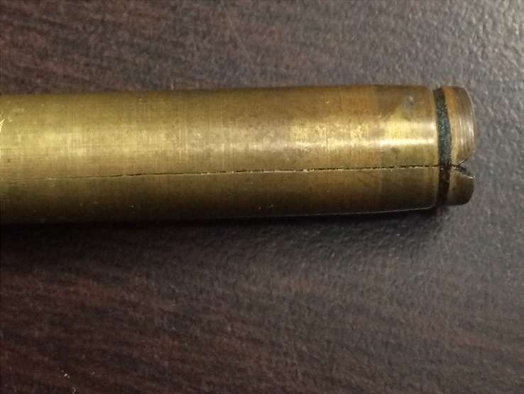
Picture 2 – Closeup of crack initiating at “v” notch
1900D - Cabin Window Damage Due to Engine Exhaust
SDR #: 20210903006
Subject:
During take-off roll from XXXX, a cabin window warped by heat detached from the aircraft (emergency exit, front right side). During the initial climb, the pilot-in-command (PIC) realized that the window was missing. The PIC returned to airport XXXX without incident. There were no injuries or fatalities and no secondary damage to the aircraft. Maintenance control determined that the most likely cause of this incident was the right engine idling for too long on the ground with the propeller in flag position.
Transport Canada Comments:
This occurrence culminated with the loss of a cabin window during or shortly after take-off. Fortunately, the aircraft was not at an altitude where an emergency descent due to pressurization loss was needed. Although frightening and distressing to the passengers, the aircraft was able to make a safe landing at the point of departure.
In 1993, Raytheon Aircraft (now Textron) published 1900 Series Airliner Model Communique No. 30 (MC-30), which highlighted a condition where cabin windows nos. 3 and 4 (single pane) were susceptible to window distortion, dishing, and shrinkage. The primary cause was identified as “hot” engine exhaust gases, and the communique listed modified operating ground procedures to minimize or avoid damage.
In 1997, the Federal Aviation Administration (FAA), the State of Design for the product, published Airworthiness Directive (AD) 97-03-01 to replace certain engine exhaust stacks, further reducing the effect of hot exhaust gases upon the windows (and wing skin de-bonding).
Since the issuance of MC-30 and FAA AD 97-03-01, there have been at least two additional window blowouts at altitude; an occurrence in South Africa, which resulted in an informative Aircraft Serious Incident Short Report CA18/3/2/1224, and a Canadian Service Difficulty Report (SDR) 20020510017.
Transport Canada Civil Aviation (TCCA) strongly suggests that owners, operators, and maintainers continue to follow all manufacturer recommendations. Special attention should be given to all single pane windows during inspection to ensure serviceability, with particular regard to “Out of Contour” defects and other possible damage listed in the Instructions for Continued Airworthiness (ICA). Any additional occurrence of window failure where published limitations and inspections have been followed, or in the opinion of the originator may affect flight safety, should be reported via an SDR.

Deformed cabin window
200 - Aviadesign Inc. Hydraulic Landing Gear Retraction System Fork End Failure
SDR #: 20081027005
Subject:
After take-off when the pilot selected gear up, the right-hand (R/H) main landing gear failed to retract. The gear was cycled again with no success. The gear was returned to the down position and there were three green lights. Dispatch and maintenance were contacted and it was decided to return to base. The landing at base was uneventful. Upon inspection by maintenance personnel, it was found that the R/H main gear actuator fork end that attaches to the upper drag brace was sheared off, however the downlock was still in place.
Upon inspection, it looked like the fork end had developed a fatigue crack and finally let go just above the lock nut that holds the fork end in place on the actuator. The fork end, and tab washer were replaced with new parts. The number of cycles or hours on the broken fork end is unknown. The gear was inspected further and no other defects were found. The gear swings were completed and all checked serviceable. The aircraft is equipped with the Aviadesign Inc. Supplemental Type Certificate (STC) SA4378WP, hydraulic landing gear retraction system, which the fork end is a part of the STC.
Transport Canada Comments:
The fork end failure in this case resulted in an unplanned but uneventful landing. As described, the downlock remained in place preventing a main gear collapse. Since this occurrence in 2008, two additional Service Difficulty Reports (SDRs) have been submitted, both (Beech 100 with Aviadesign STC SA4013WE) with a less desired outcome, a main gear collapse while the aircraft was parked overnight.
Beechcraft rigging geometry provides a positive lock at full extension. The Aviadesign actuator fork end failure should not result in a downlock disengagement and gear collapse. Contributing factors for the gear collapse could include, incorrect downlock rigging, incorrect Aviadesign hydraulic actuator installation/rigging, or external factors such as high winds.
Transport Canada Civil Aviation (TCCA) suggests that owners, operators and maintainers pay close attention to correct rigging instructions and cautions outlined in the STC holder and Beechcraft maintenance manuals. Additionally, any defects noted in the Aviadesign fork end should be reported as an SDR.
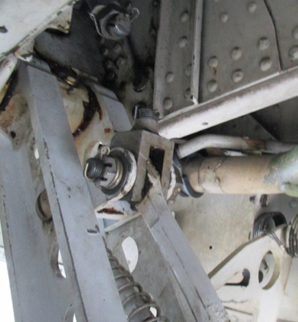
Picture 1 – Fork end failure in situ (SDR 20210316004)
Picture 2 – Fork end failure close-up (SDR 20081027005)
Lockheed
L100-382 - Wing Bolts Received New From Supplier Were Found Cracked Before Installation
SDR #: 20180706010 & 20180706012
Subject:
Minor edits have been made to the text below taken from the Service Difficulty Report’s Problem Description. Transport Canada Civil Aviation reserves the right to edit for spelling, grammar and punctuation to increase comprehension.
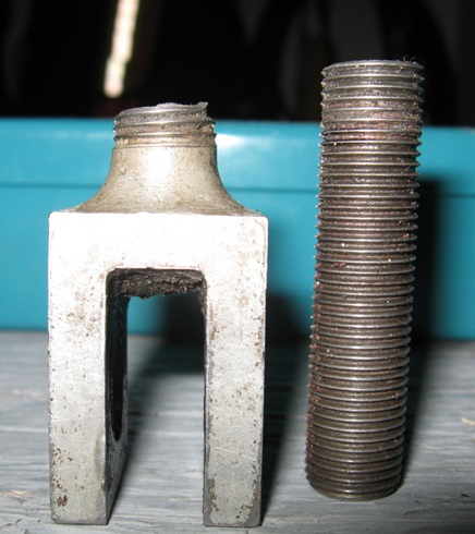
A batch of bolts (part number (P/N) MS21250-12032) was procured in a lot of 50 for use as wing attachment bolts on a Canadian military CC130H Hercules aircraft. Prior to installation, the Royal Canadian Air Force (RCAF) technical order requires that the bolts undergo magnetic particle testing. During the magnetic particle testing, one bolt was found to be cracked longitudinally in the bolt head.
A batch of bolts (P/N MS21250-14038) was procured in a lot of 26 for use as wing attachment bolts on Canadian military CC130H Hercules aircraft. Prior to installation, the RCAF technical order requires that the bolts undergo magnetic particle testing. During the magnetic particle testing, four bolts were found to be cracked longitudinally in the bolt head.
The same bolts are used in civilian registered Lockheed L100-382 Hercules aircraft.
Transport Canada Comments:
Due to the pre-installation testing requirements for these wing attachment bolts, the defective bolts were discovered and not installed on the aircraft. As these bolts were installed in a critical component, the operator/military had additional inspection requirements before installation. This occurrence shows the importance of good quality control practices when using standard aviation hardware which can be procured from many suppliers.
This was a military aircraft and a military required inspection process that could be easily adapted for use on civilian registered Hercules aircraft and provide additional safety. Additional inspection requirements like this are a good safety practice when standard hardware is used in critical areas.

Figure 1. MS21250-12032 bolt showing area where crack was found
CANADAIR
CL215 6B11 (CL415) - Blocked Vent Openings
SDR #: 20210719024
Subject:
The aircraft was dispatched to a forest fire on 17 July 2021. After start up, the flight crew found the right-hand (R/H) low fuel pressure light on. The aircraft was shut down and the snag was reported to maintenance.
The Aircraft Maintenance Engineer (AME) attempted to troubleshoot the aircraft system, but upon selection of the #2 battery to the ON position, no power was observed on the aircraft. Subsequent troubleshooting of the #2 battery system revealed that the #2 battery case was distorted and the battery lid was bent. The battery was removed from the aircraft for further inspection.
There does not seem to be any evidence of the battery overheating, and the battery was cool when the defect was found. The battery voltage still read 24-25 volts. Removal of the battery lid revealed that the thermal switch was defective with an internal short or other failure. We can also see that one of the cells within the battery was cracked.
We have completed the initial inspection of the aircraft, and have found the pressure portion of the battery vent system plugged (insect). We have been in contact with the aircraft manufacturer (Viking) and have been trying to contact the battery manufacturer to address the cause of the distorted case. All other aircraft in the fleet have been inspected for battery case distortion, and no thermal switches with defects were found. The battery vent systems of the fleet have also been inspected and cleared of any obstructions.
Transport Canada Comments:
This particular defect was found on the ground but could have been worse if it had been found during flight. Transport Canada Civil Aviation (TCCA) would like to remind operators, maintainers and ground service personnel of the importance of being vigilant for possible ingress of dirt, insects etc. in aircraft systems vent openings. The latter would include, without limitation, pitot-static openings, fuel system vents and, as in this case, battery venting openings. Obstructions of venting provisions on an aircraft can lead to more serious problems.

Defective battery
CL600 2B16 (601 3R) - New Tire Found With Metal Protruding From Sidewall
SDR #: 20180716012
Subject:
Minor edits have been made to the text below taken from the Service Difficulty Report’s Problem Description. Transport Canada Civil Aviation reserves the right to edit for spelling, grammar and punctuation to increase comprehension.
Following the installation of a new tire on the aircraft main wheel during the tire inflation and pressure test, the maintenance personnel noticed a piece of metal protruding from the tire sidewall. When the tire was installed and prior to inflation, the piece of metal was not visible. The tire was a new part received from a supplier who had received it from the original equipment manufacturer (OEM).
Transport Canada Comments:
It appears that during manufacture of the tire, a piece of metal fell into the mold and was molded into the tire sidewall. The tire manufacturer’s post-inspection requirements (Quality Control) did not detect the foreign object inside the tire sidewall. The defect was not discovered until the tire was inflated by maintenance personnel after installing the tire. The supplier and tire OEM were advised of this event by the operator and Transport Canada Continuing Airworthiness.

Fig 1: Metal showing after inflation close-up

Fig 2: Metal protruding

Fig 3: Indications metal was molded into tire

Fig 4: Metal removed
Incorrect Hook and Loop Installation on Emergency Locator Transmitters (ELT)
SDR #: 20181203023
Subject:
Minor edits have been made to the text below taken from the Service Difficulty Report’s Problem Description. Transport Canada Civil Aviation reserves the right to edit for spelling, grammar and punctuation to increase comprehension.
It was noticed during an annual inspection that the Velcro strap (included with the S1840502-01 mount) was found with the metal buckle directly overtop the top face of the ELT. As per the Kannad Aviation installation/operation manual, the metal buckle must be positioned on the left or right of the ELT only. The position is listed as a caution that incorrect installation of the Velcro strap could lead to an unsafe condition. Upon removal of the strap, it was found that the factory-installed Velcro strap had its small Velcro tab (which attaches to the backside of the mount to orient the Velcro strap) incorrectly attached to the strap approximately 5.5” from the buckle (normal is approx. 3.5”). This allows for the Velcro strap to be installed incorrectly without the installer knowing it is incorrect (unless they are aware of the proper procedure and figure within Kannad’s manual). The Velcro strap itself does not have a part number, it is only listed as “included with the bracket mount.” It is unknown if this Velcro tab is meant to be glued, sewn, or otherwise attached to the Velcro strap. It is also unknown if it is required for the Velcro strap to be considered in a serviceable condition.
Transport Canada Comments:
This Service Difficultly Report (SDR) is an excellent example of observing an incorrect installation that could have led to a possible malfunction of the ELT in an emergency situation.
The Federal Aviation Administration (FAA) published Special Airworthiness Information Bulletin (SAIB) HQ-12-32 to inform ELT manufacturers, installers and aircraft maintenance personnel of a concern of hook and loop-style fasteners’ ability to restrain ELTs during accident impact. Subsequently, Kannad Aviation published service bulletin (SB) S1800000-25-00 to outline the instructions for properly securing the ELT during installation and reinstallation. In addition to the SB, Kannad Aviation has also published service letter (SL) SL S18XX502-25-12 to provide instruction for completing the Canadian Aviation Regulations (CARs) Part V & VI ELT periodic testing and inspection requirements. The SL also directs the reader to multiple bolded caution messages related to the incorrect installation of the hook and loop fasteners. Seemingly simple work should not be overlooked; it is important at all times to read each manufacturer’s installation instructions and instructions for continued airworthiness to correctly complete the job.

Image 1 – Example of an incorrect installation of the hook and loop fastener with metal buckle on the face of the Kannad 406 AF ELT.

Image 2 – Example of the correct installation of the hook and loop fastener where the metal buckle on the side of the Kannad 406 AF ELT.
Bombardier
CL600 2B19 (RJ100) - CRJ100/200 – Aft Cargo Door Fitting Cracked
SDR #: 20210304004
Subject:
During a scheduled inspection, a crack was observed on the aft cargo compartment door forward upper door fitting. Fitting to be replaced with a serviceable part.
Transport Canada Comments:
The defect was found during a scheduled inspection and there doesn’t appear to be movement or smoking, the inspector who found it was doing a thorough inspection. As aircraft age, more wear and fatigue defects can occur. The cargo doors are opened and closed many more times than there are cycles on the aircraft, as such, this area is one which can be susceptible to damage.

Picture 1: Door fitting crack location

Picture 2:Close-up of the cracked area

Picture 3: illustrated parts catalog showing door fitting
Text in the picture: Pre MOD, Post MOD, Baggage bay door assembly
CL600 2D24 (RJ900) - RJ900 – Fuselage Stringer 20R Corrosion
SDR #: 20200127017
Subject:
During a maintenance check, it was noted that stringer S20R had corrosion damage from fuselage station (FS) FS.927 to FS.954. The corrosion was found when the floor was removed and was located below the underfloor ducting. There was 100% material loss found and the stringer had to be replaced. The final repair was a replacement of the corroded stringer section from factory stringer splices at FS.920 and FS.977.
Transport Canada Comments:
When localized corrosion is found there is usually a specific cause, and in this case the severely corroded area was located beneath an underfloor air duct. The air duct would have carried hot or cold air, and the underfloor area would have been the opposite temperature, either cold or hot and humid. In either case, this is a recipe for condensation and moisture creation and made the area susceptible to corrosion. Access to the area is hidden from the view of most general visual inspections (GVIs) and was only found when the floorboards were removed. If the corrosion had been discovered sooner, a stringer replacement may not have been needed, so more frequent inspections of this area are recommended.

Figure 1: Area of damage location

Figure 2: Location and material loss

Figure 3: Closeup of corrosion
CL600 2D24 (RJ900) - RJ900 – Aft Cargo Compartment Floor Beam Corrosion
SDR #: 20190531002
Subject:
During a scheduled maintenance check in the aft baggage compartment, the longitudinal cargo floor structural floor beam on the left-hand side at Fuselage Station FS.1000-1031 was found corroded. The area is located near the aft baggage door opening, and after close inspection, the floor beam was discovered to be corroded completely through with a hole at one location. This level 2 corrosion was under the floor track in the noted area and the floor beam section had to be replaced in accordance with approved repair data from the manufacturer.
Transport Canada Comments:
The corrosion found in the aft cargo compartment was severe and localized. This type of corrosion is often caused by a spill of a corrosive compound. Another possible cause of this corrosion, is an accumulation of compounds and/or spills. Regardless of what caused the localized corrosion, the defect was found by an inspection crew conducting a thorough inspection, and the damage was repaired. Care and caution should always be the norm when loading cargo, and if a spill occurs or is noticed, it should be reported to maintenance staff immediately so it can be properly cleaned to prevent damage of this nature.

Fig 1: Floor beam cut out - Aft cargo compartment

Fig 2: Localized corrosion damage on floor beam

Fig 3: Close up showing corrosion right through beam
CL600 2D24 (RJ900) - Level 2 Corrosion – Passenger Door
SDR #: 20190313002
Subject:
During scheduled maintenance, level two corrosion was observed within the passenger door structure below the door handle cut-out. Repairs were carried out in accordance with the structural repair manual and required the replacement of channel part number 601R318057-1 due to the extent of the corrosion damage. The aircraft had accumulated 42 008 hours air time and 21 756 flight cycles at the time the corrosion was found.
Transport Canada Comments:
The corroded area exhibited extensive deterioration, including pitting and flaking of metal. Aircraft maintenance program inspection intervals should be sufficient to ensure that corrosion is found at level 1 or below before progressing to level 2 and beyond, as was found in this case.
Issues with excessive corrosion at the passenger door area are being reported more frequently, and the number of Service Difficulty Reports (SDRs) indicates an increasing trend. The passenger door is a high traffic area and can accumulate contaminants and moisture on a daily basis and at all times of the year. This area requires frequent and regular detailed inspections including cleaning of the drain holes. Following each inspection, preventive measures such as the application of corrosion inhibiting compounds (CIC) is a recommended industry practice. By following these criteria, an operator’s maintenance program can prevent damage like was found here.
In Canada, if an operator finds corrosion such as was reported here, Transport Canada expects the operator to review all similar corrosion events to determine if there is a trend. If a trend is discovered, the operator’s Maintenance Schedule Approval (MSA) procedures should be reviewed and amended to perform shorter interval inspections to maintain corrosion at an acceptable level. The MSA amendment procedures are found in TP 13097 Chapter 2, Section 9 and are required by Canadian Aviation Regulation (CAR) 406.07 and CAR 706.07.

Fig 1:Corrosion damage

Fig 2: Close-up of corrosion showing depth and flaking

Fig 3: Location of corroded area
CL600 2D24 (RJ900) - Ram Air Heat Exchanger Ducts Cracked
SDR #: 20190412003
Subject:
During unscheduled maintenance actions in the aft equipment compartment, the aircraft maintenance engineer (AME) observed that the left and right ram air heat exchanger diffuser ducts were cracked and separated from their respective heat exchangers. The diffuser mating surfaces had pulled through the attaching hardware, the duct flanges were broken and the ducts were cracked.
Transport Canada Comments:
The damaged ducts were found on a RJ900 that had been in service for 14 years. The cracking was so severe that at least half of each duct attachment was completely detached from the heat exchangers. The cracked ducts were found by alert maintenance personnel during the performance of an unrelated maintenance event. This finding illustrates the value in carrying out a general visual inspection (GVI) of the area when performing maintenance because something else needing attention may be discovered.

Fig 1: Left-hand (LH) duct aft and outboard showing separation from heat exchanger

Fig 2: LH duct aft edge separated

Fig 3: Right-hand (RH) duct outboard

Fig 4: RH duct inboard and front showing separation from heat exchanger

Fig 5: Parts manual showing the cracked ducts
BD 500 1A10 - Nose Landing Gear (NLG) Collapsed Oleo Events
SDR #: 20180208005
Subject:
Minor edits have been made to the text below taken from the Service Difficulty Report’s Problem Description. Transport Canada Civil Aviation reserves the right to edit for spelling, grammar and punctuation to increase comprehension.
The Nose Landing Gear (NLG) oleo strut collapsed in-service. After touchdown, a very strong shimmy and vibration from the nose gear was observed. The same shimmy and vibration was observed at the (2) previous landings. During the arrival inspection, the NLG was found deflated and fully collapsed. Further inspection found the groove nut touching the sliding tube and the gland nut locking washer displaced and bent.
Recommendations for repair from Liebherr were requested by the operator and the Flight Data Recorder (FDR) data was downloaded for readout and troubleshooting. Bombardier and Liebherr recommended inspections were carried out before returning the aircraft to service.
Transport Canada Comments:
A number of in-service events occurred in early 2018 on very low time NLG assemblies where the oleo lost fluid and nitrogen. These events occurred on NLG oleos with times in-service between 603 to 3346 flight cycles and 1373 to 3592 hours air time. In two (2) of the cases, the oleo gland nut lock ring was damaged and was actually pulled out of place. The landing gear manufacturer attributes the lock ring damage as a result of turning the aircraft with the oleo fully deflated. One air turn back also occurred because the NLG would not retract and when investigated, it was discovered that the oleo had lost fluid and was not at proper extension.
In some of the cases it is believed that the aircraft may have been dispatched with a flat oleo, as evidenced by the investigations and reported crew observations while operating the aircraft on preceding flights. The oleo outer cylinder lower portion is chrome and not painted which is unlike most other aircraft landing gear. It may be possible to assume that the oleo is inflated and has some extension when in fact the oleo is flat and has no extension because of this chromed area. Refer to the attached pictures figures 1 through 3 showing a deflated /collapsed oleo.
In February 2018, Bombardier issued Service Letter (CS-SL-32-20-0001) to inform operators to perform a pre-flight inspection for proper oleo extension. In November 2018, to address the loss of fluid and nitrogen, Liebherr issued Vendor Service Bulletin (VSB) 4124A-32-04 to upgrade the lower cam, dynamic seals and the scraper seal of the NLG shock strut assembly. These changes are intended to reduce the possibility of a NLG shock strut sudden leakage in-service. At the time the VSB was issued it applied to 71 affected aircraft of which 14 had been modified. All aircraft delivered, after the VSB was issued, have this upgrade before delivery. The incorporation of this VSB modification on shock strut assembly Part Number (P/N) 4124A1000-04 changes the shock strut assembly to P/N 4124A1000-05 so it is easy for operators to confirm the VSB has been incorporated.
The last event occurred in January 2019 and according to the Service Difficulty Report (SDR) information, the oleo was reported as P/N 4124A10000-4 which is the P/N of a pre-VSB oleo. This VSB incorporation is strongly recommended so operators should confirm that they have P/N 4124A10000-5 oleos.

Figure 1: Fully collapsed oleo with locking ring damaged

Figure 2: Close-up of gland nut lock ring pulled out and collapsed oleo

Figure 3: Another aircraft with similar fully collapsed oleo and bent and damaged gland nut lock ring. Note silver colour of outer cylinder

Figure 4: Oleo shown with proper extension in serviceable state
CL600 2D15 (705), CL600 2C10 (700, 701, 7020 and CL600 2D24 (900)
Frame corrosion under forward passenger door
SDR #: 20170817016
Subject:
While investigating an unrelated defect, corrosion was found in the area under the floor near the passenger door. Maintenance staff removed and replaced the intercostal from frame fuselage station (FS) 310 to 333.00 and from stringer (STR) 25L to 26L as per Structural Repair Manual (SRM) 51-00-00 and Bombardier Aerospace drawing number SH670-31810. Additional corrosion was discovered on the foot of the frame at FS 319.70 between STR 20L to 21L. This frame was also removed and replaced with a new frame as per SRM 51-00-00 and Bombardier Aerospace drawing number SH670-31810. Please see the attached pictures to view the damaged pieces and severity of the corrosion.
Transport Canada Comments:
While the submitter does not specify a cause, it is likely that the corrosion was the result of water and moisture that passed through the floor and accumulated in the bilge area. This location is susceptible to water ingress because it is a high traffic area and is often subjected to the outside elements such as rain and snow. When the stairs are raised, any water or melting snow will also drip onto the floor and may then pass through the floor seals. On many models of this aircraft a galley is also located nearby, providing opportunity for spilled liquids.
After discovering this corrosion, the operator chose to update its company’s corrosion protection and control program, to better address this issue.

Corroded intercostal

FS 319 frame corrosion

View of corrosion in situ

Heavily corroded structure

Illustrated parts catalogue(IPC) showing location
CL600-2D24 (RJ900)
Circuit Breaker Panel Burned Through
SDR #20161121006
Subject:
The left hand cockpit main circuit breaker panel was burned through when a foreign metal object contacted the windshield wiper circuit breaker and grounded to the panel door skin. The ensuing electrical arcing burned through the panel creating a hole.
Transport Canada Comments:
The burnt part of the panel is actually a door which hinges down in order to provide access to the circuit breakers for maintenance and inspections. It is likely that during some previous maintenance event that the foreign object was dropped or left inside the panel. The object then moved and shorted out the wiper circuit breaker causing the damage to the panel door.

Panel showing external hole width

Panel showing external hole height

Panel inside showing burnt rail hole size inside panel
CL-600-2D15 (705)
Equipment Airworthiness Directive on Crew O2 Mask
SDR #20161020005
Subject:
The oxygen mask was received for servicing and the defect noted was "observer mask has a hole in it". Upon inspection and teardown, it was found that the harness assembly was 12 years old and blown. The manufacturer recommends to replace the inflatable harness assembly every 6 years. Upon further inspection, a number of other discrepancies and evidence of improper/substandard maintenance were noted.
The main concern/problem is a blown inflatable harness with over 12 years of service indicates a lack of proper inspection and recommended maintenance. There were no inspection letter markings found on the harness indicating that Zodiac service bulletin (SB) MXH-35-241 was carried out. This SB was required by EASA airworthiness directive (AD) 2011-0090R1 and dates back to June 23, 2011 with accomplishment instructions within 24 months.
The mask assembly was manufactured in November 2001, and the combined diaphragm was dated 2004 which indicates no proper maintenance or overhaul had been done since new. It was also noted that the main casing which was dated October 2009 was replaced during a repair accomplished in 2010, however the combined diaphragm dated 2004 was put back into the regulator.
Service information letter (SIL) 18 recommends replacement of the harness every 6 years, and overhaul every 6 years.
Transport Canada Comments:
The submitter raises some good points and references the recommended intervals recommend by the manufacturer and the SIL. The question about the operator’s compliance with the EASA equipment AD 2011-0090R1 is certainly a concern. This equipment AD is effective in Canada and is in the Continuing Airworthiness Information System (CAWIS) database.
The manufacturer’s and the SIL recommendations are not necessarily a mandatory overhaul requirement. These items are manufacturer’s recommendations and used to make and amend an operator’s maintenance schedule approval (MSA). The MSA requirements and intervals may be the same or different depending on the actual Transport Canada MSA approval for the operator.
Without knowing the history of this line replaceable component and the installation and removal data, it is difficult to assess the missed AD compliance issue. Operators must be diligent in monitoring all applicable equipment ADs to remain in compliance with Canadian Aviation Regulation (CAR) 605.84 requirements, because they can come from many civil aviation authorities.
Transport Canada is publishing this article to raise awareness in regards to equipment maintenance and equipment ADs.
Penney & Giles Aerospace Ltd Multi-Purpose Flight Recorder (MPFR) Internal Corrosion
SDR #: N/A
Subject:
Minor edits have been made to the text below taken from the Service Difficulty Report’s Problem Description. Transport Canada Civil Aviation reserves the right to edit for spelling, grammar and punctuation to increase comprehension.
Data recovery on certain Penney & Giles Aerospace Ltd Multi-Purpose Flight Recorders (MPFRs) have been found to be problematic where the aircraft was submerged in water. Corrosion on pins of memory devices, due to an insufficient amount of conformal coating, may occur when subjected to water.
Certain “GEN2” memory modules manufactured between 6 April 2006 and 2 January 2013 may be susceptible.
Transport Canada Comments:
The European Aviation Safety Agency (EASA) has issued Safety Information Bulletin (SIB) 2018-05 highlighting this issue, and recommends owners and operators accomplish the actions specified in Penny & Giles Aerospace Ltd Service Bulletin (SB) No. D51615-31-22. Penney & Giles Aerospace Ltd will work with the operator to schedule an upgrade of the “GEN2” memory module in the affected serial number range.
Although this is not considered to be an unsafe condition that would warrant an Airworthiness Directive (AD), Transport Canada would like to highlight, that it is the owner’s responsibility to verify applicability of miscellaneous equipment ADs. In addition, as best practice, operators should be checking SIBs and Special Airworthiness Information Bulletins (SAIBs) etc. of foreign authorities.
Piper
PA31 350 - Anti-retraction Solenoid for the Piper PA31-350 Landing Gear Selector
SDR #: 20171108018
Subject:
Minor edits have been made to the text below taken from the Service Difficulty Report’s Problem Description. Transport Canada Civil Aviation ( TCCA ) reserves the right to edit for spelling, grammar and punctuation to increase comprehension.
The pilot inadvertently selected gear-up upon landing, resulting in the aircraft, engines and propellers being badly damaged. The landing gear selector mechanism should prevent selecting gear-up with weight on wheels. At the time, it was thought that the gear was selected up just at the moment of touchdown while the wings still had lift and the gear struts were still fully extended. The aircraft was repaired and returned to service.
However, during subsequent maintenance to repair defects noted by the pilot, the Aircraft Maintenance Engineer (AME) checked the landing gear selector mechanism without power-on and he could select “gear-up” without the anti-retraction locking pin stopping the handle. The AME investigated further and removed the anti-retraction portion of the landing gear selector mechanism. The AME found that the solenoid assembly shaft was bent and was stuck in the stop lever hole.
When the shaft was rotated 90 degrees, the solenoid could then move freely through the stop lever hole. Inspections conducted since the gear-up incident had found that the solenoid assembly worked properly, preventing the landing gear selector handle from being selected up. At every 100 hours air time, the PA31-350 event # 2 and # 4 inspections call for inspecting the landing gear selector mechanism and the anti-retraction solenoid.
With the solenoid installed, a bent shaft is not obvious and it would be difficult to detect unless the shaft was stuck in the stop lever hole. If the AME were to rotate the shaft during the inspection, a bent shaft would likely be found. This idea was not considered during previous inspections, nor considered necessary as the solenoid operated normally. Piper may want to add to their inspection requirements, to rotate the solenoid shaft in-situ by finger at the spring flange.
Transport Canada Comments:
The Piper PA31-350 (Chieftain) is one of several models of Piper aircraft equipped with a very similar landing gear selector handle with an anti-retraction solenoid as described in this service difficulty report ( SDR ). A quick search of the web service difficulty reporting system (WSRDS) database reveals that there have been over 40 SDRs filed since 1975 with respect to issues pertaining to the landing gear selector handle and anti-retraction solenoid. Some of these incidents resulted in unplanned retractions on the ground with consequential damage to the aircraft. In April 2007, the Transportation Safety Board (TSB) investigated an accident under TSB file A07O0095 where the aircraft suffered a retraction of the landing gear just after landing. The cause was attributed to a broken spring in the landing gear handle which weakened the handle’s ability to return to its most forward spring-loaded position and allowed the handle to move past the neutral stop when it was most likely inadvertently bumped.
Piper released Service Letter No. 492, dated September 6 1967, which provided general instructions for inspection and operation of the landing gear handle. In addition, Piper incorporated the intent of that inspection into the Piper PA31 Service Manual and added a specific requirement to check the anti-retraction solenoid at every event # 2 and # 4 as described in the SDR .
The submitter’s finding in this SDR , that the manual does not specifically require the technician to rotate the shaft to verify that it is not bent, is a valuable observation. Even though it is not specifically called out in the Instructions for Continued Airworthiness (ICAs), TCCA highly recommends that maintainers of these types of aircraft be diligent in inspecting for this condition (bent shaft) specifically, in addition to other negative conditions (e.g. weak return springs in handle, proper alignment and functioning of anti-retraction solenoid and or squat switch etc.)
TCCA also reminds maintainers and operators that if any such conditions are found, to submit an SDR to TCCA .

Piper PA31-350 Landing Selector
Text that appears in the image:
Up-neutral position
Lever
Gear handle
Gear handle pin (down-neutral position)

Piper PA31-350 Anti-retraction solenoid
AEROSPATIALE
ATR 42 and ATR 72 Side Window De-ice Burnt Terminals
SDR #: 20190925002, 20171012009, 20190927006
Subject:
The side window anti-ice activated at approximately 4000 feet (ft). By approximately 2500 ft, the pilots could smell electrical smoke, followed by dark grey smoke emitting from the first officer’s side window. At this point, the aircraft was clear of the cloud. The side window anti-ice was de-activated, and Air Traffic Control (ATC) was notified that the aircraft was on final approach with smoke in the cockpit. Upon landing, the side window and the electrical connection for the side window heat began to burn and melt. The aircraft taxied off the runway, with small flames becoming visible. The aircraft was shut down and the handheld fire extinguisher was discharged on the burning portion of the window and the associated electrical connection. The initial investigation points to the fire starting at the positive stud on the electrical connection. There is no evidence of arcing of the positive wiring to the airframe, and it appears to have started internally in the phenolic housing.
Transport Canada Comments:
Multiple events of flight compartment side window arcing have been reported. ATR-GIE and Saint-Gobain Sully (window manufacturer) initiated an extensive technical investigation to determine the cause.
The origin of the arcing was located at the electrical connections between the aircraft power supply and the connector of the side window (fastener with three screws and nuts).
The technical investigation shows that a mechanical clearance between the aircraft crimp ring and the connector screws may cause an increase in the contact resistance and a local overheating/arcing at the level of the crimp rings (terminal lugs) and fasteners.
The technical investigation determined the most appropriate torque to be applied and added an additional nut to the terminals.
Transport Canada Civil Aviation would like to advise ATR 42 and ATR 72 series aircraft operators of the issuance of ATR Airworthiness Operators Message AOM 2021/08 Issue 1. This AOM guides certain aircraft operators to Vendor Service Bulletin (VSB) 56-12-00-SPSATR42 and provides other operators with information on using the new torque values.

Picture 1 – Burnt window de-ice terminal lugs

Picture 2 – Side window de-ice terminal - old installation

Picture 3 – Side window de-ice terminal – new installation
ATR 42 320 - Small bulb, big problem
SDR #: 20150224028
Subject:
Minor edits have been made to the text below taken from the Service Difficulty Report’s Problem Description. Transport Canada Civil Aviation reserves the right to edit for spelling, grammar and punctuation to increase comprehension.
A small amount of smoke was noted in-flight, emitting from the reading light in seats 5A/B. The aircraft returned to base and the bulb was replaced rectifying the defect. The company’s safety management system investigation lead to the suspicion that the bulb was an unapproved or counterfeit part. Indications of the part being counterfeit are low quality and overabundance of solder on positive (NON BODY) electrical contact. A complete lack of manufacturing markings or part number (P/N) stamped or etched on the bulb, a lack of solder to secure the bulb housing halves joint, and a smaller than normal insulator separating the bulb housing and center contact.
An inspection of a second company’s aircraft found approximately 1/3 of the bulbs installed in the reading lights were of the unmarked, suspected counterfeit variety and several had significantly melted contacts. Upon this discovery, the reading light system on all 5 company aircraft were deferred and disabled until all the bulbs could be inspected and replaced as required.
Transport Canada Comments:
Within the quality assurance program for your company, the final quality control rests with the installer, and constant vigilance is required at all times. It is a good practice that maintainers installing parts ensure that they are using correct parts by visually comparing the new and the replacement. A correct P/N does not always guarantee that you have the right part.

Diagram showing the differences between the unapproved part and a Parts Manufacturer Approval (PMA) unit.
ATR 42 - Wheel Assembly Tie Bolt Failures
SDR #:
It has come to the attention of Transport Canada through the Web Service Difficulty Reporting System (WSDRS) that numerous operators of the ATR-42 series aircraft, have had main wheel tie bolts found sheared or missing.
Over the past year, nine SDRs have been submitted via the WSDRS for this problem.
Typically, the operators have reported hearing an odd sound emanating from the wheel assembly while towing the aircraft in the hangar or from the gate. Upon further inspection, most operators find the remains of a tie bolt loose within the cavity between the brake system and the wheel. Other operators have detected the problem upon removal of the wheel assembly, due to tire wear or one operator found the wheel assembly would not hold air pressure.
The manufacturer of the wheel assemblies, Meggitt Aircraft Braking Systems, issued service bulletin (SB) ATR42-32-33, dated June 14 1999, to attempt to address this issue. Meggitt has introduced through this SB an increased torque value and torqueing sequence for the tie bolts, as well as specific cautions as to the use of power and automatic tightening devices.
Most operators send their wheel assemblies out to overhaul facilities for repair and non-destructive testing (NDT) as applicable. It is recommended that the operator ensure the overhaul facility is following the most up-to-date information prior to performing the overhaul and assembly of these wheel assemblies. Special attention should be given to the tie bolts themselves. The Meggitt component maintenance manual (CMM) for the wheel assemblies in the part number 5006856 series has specific instructions pertaining to the inspection of the bolts and nuts, including a Magnetic-Particle Inspection (MPI) for cracks, paying particular attention to the radius under the bolt head and to the threads adjacent to the bolt shank.
The CMM also states “An equivalent bolt maintenance program may be established by aircraft operators with service experience whereby bolts are replaced based on usage.”
Transport Canada recommends following the CMM and SB ATR42-32-33 while operating these wheel assemblies. Doing this should give operators of the ATR-42 series aircraft the life expected from these components.

Missing main wheel tie bolt

Backed out main wheel tie bolt

Sheared nuts from main wheel tie bolts
Boeing
767 328 - Bleed Air Pre-Cooler Air Leak
SDR #: 20180424017
Subject:
Minor edits have been made to the text below taken from the Service Difficulty Report’s Problem Description. Transport Canada Civil Aviation reserves the right to edit for spelling, grammar and punctuation to increase comprehension.
During a regular maintenance visit, metal debris was found protruding from the right hand pre-cooler exhaust outlet of the core cowl. Further inspection revealed separation of the pre-cooler shroud and core cooling fins. Engine bleed inlet and exhaust ducts were inspected for debris, with no debris noted. The engine bleed outlet fins were intact.
The pre-cooler was replaced, along with the right hand engine strut blanket and outboard core cowl. No further damage was sustained due to the separation. There was no evidence noted as to the cause of this defect. No indications were noted by the flight crew prior to the discovery of this defect.
Transport Canada Comments:
Further investigation by this operator revealed the probable cause of the failure to be sulfidation. Sulphur compounds in the air are chemically reacting with the nickel causing the fins to become brittle and flake off. If enough fin material is lost, leading to the pre-cooler not being able to adequately cool the bleed air, eventually the core could collapse.
In this case, the piece of the core that let go internally caused the side wall of the cooler to become compromised. The resulting large hole allowed material to escape and cause secondary damage to the engine strut blanket and outboard core cowl.
This is a good example of how alert maintenance personnel exercising awareness during maintenance activities and looking beyond the immediate task can find problems before they manifest into more serious events.

Pic 1: Pre-Cooler Assembly with pieces from housing

Pic 2: Close up view of the hole in the housing and missing fins on the internal structure.
757-2B7 - The Effects of Skydrol
SDR #: 20171004006
Subject:
While approaching the gate, the crew noticed a "left hyd. Qty." warning message appear. The aircraft was brought to a stop at the gate, and shut down normally. Maintenance noticed a large hydraulic leak from the left gear bay, and a total of 5 ramp personnel assisting with marshaling the aircraft were exposed to the atomized skydrol as a result of the high pressure leak. The ramp personnel affected were taken to the hospital with various symptoms, including vomiting. Maintenance staff found the cause of the leak, which turned out to be a ruptured hydraulic line going to the down lock actuator, and subsequently replaced the unserviceable component.
Transport Canada Comments:
This SDR reminds us of the effects of Skydrol on the body. These individuals were not expecting to be in contact with the chemical. When you are anticipating the potential of contact with Skydrol, please wear proper personal protective equipment (PPE) such as gloves and eye protection.
Engines and APU’s
Oil Servicing Safety Issues
SDR #: Not applicable
Subject:
Oil servicing issues continue to occur in the aviation industry, including over and under servicing engines, failing to properly secure oil filler caps and failing to latch access doors/panels. These events can lead to loss of oil and engine shutdown, smoke or odors in the cabin and loss of panels in flight.
Human factors studies tell us that the reason for these events can include complacency, fatigue, distraction, a lack of experience, inadequate training, etc. A properly implemented Safety Management Systems (SMS) can help reduce occurrence rates.
When Transport Canada receives reports of these (and other) types of occurrences, the information is passed on to the type certificate holder (TCH) of the affected product. Transport Canada Continuing Airworthiness works with the TCH towards reducing both the rate of occurrence and the impact.
Some of the resulting corrective actions may include: design changes (such as check valve installation on oil filler necks), awareness campaigns through various publications and revised labeling and placarding.
Maintainers must remember that although oil servicing is a routine task, it is absolutely vital to flight safety. Servicing tasks (however routine they may seem) need to be carried out correctly and completely, in accordance with the latest manufacturer’s instructions. It is worth noting that manufacturers’ websites are excellent resources for safety information regarding the operation and maintenance of their products.
V-Band Couplings and Clamps
Maintenance of V-Band Couplings and Clamps
SDR #: 20170404021
Subject:
Best Practices for Maintaining V-Band Couplings / Clamps
Transport Canada Comments:
V-band couplings and clamps can be found on many general aviation and commercial aircraft. These units are frequently used to attach exhaust and turbocharger assemblies. This important, yet often overlooked item, plays a critical role in the function and safe operation of the aircraft. Failure of these items has led to serious in flight emergencies including engine power loss, engine failure and in flight fire. The difficulty with these items is that due to the nature of the installations, they are often extremely hard to inspect. Some of the issues that can arise from normal operation (due to the harsh operating environment) can include cracking, loosening of fasteners and weld breaks. It has been reported to Transport Canada that some of these units from PMA (Parts Manufacturing Approval) manufacturers have failed even when new (as seen in the photo below –spot welds not holding together).
Recently the Federal Aviation Administration (FAA), in conjunction with an industry working group, released a ‘best practices guide’ regarding V-band couplings / clamps. This article contains a great deal of valuable information regarding the installation, inspection and maintenance of these units. Transport Canada recommends that operators and maintainers of aircraft equipped with these couplings review this article. The following is the link to the FAA best practice guide:
https://www.faa.gov/aircraft/air_cert/design_approvals/small_airplanes/cos/aging_aircraft/media/maintaining_exhaust_system_best_practices.pdf

V-Band Coupling and Clamp
Diamond
DA-20-C1
Teledyne Continental Motors Ignition Switches
SDR #: 20170623010
Subject:
Note: TCCA has made minor editorial changes and additions to the original text of the SDR, for improved reading and better logic flow.
The aircraft was snagged for “engine won`t start”. Troubleshooting was carried out and maintenance found the ignition switch to be faulty. The switch was checked in accordance with Diamond DA20-C1 aircraft maintenance manual (AMM) chapter 74-00-00, p 201- ignition switch test #2, item number 3 on page 202. When tested in the “start” position, the left retard was found to be “open” which was correct, but it was also found that the left and right advance cable points were “open”. These contact points should have read zero ohms or “closed”. A new switch was obtained from the company’s primary base of operation. It was tested in accordance with the AMM, found serviceable and installed.
The defective switch had been replaced for troubleshooting purposes due to an “erratic starter engagement” the previous week. The switch was not checked for correct continuity at that time of installation and had accumulated 21.1 hours in service.
During the current snag troubleshooting, when the switch was found to be defective, there were no new switches in stock at the company’s sub base, so a serviceable switch was removed from an aircraft down for a 1500 hour inspection. When that switch was tested prior to the planned installation to rectify the snag, the then removed serviceable switch was found to have the same defect as the switch with the 21.1 hours in service. The total time in service of the removed serviceable switch is unknown at this time and there is no record of replacement within the previous 6 months. The removed serviceable switch was red tagged and placed in quarantine stores.
Transport Canada Comments:
The original equipment switch part number (P/N) listed in the DA20-C1 Illustrated Parts Catalog (IPC) is shown as being P/N A-510-2. The latter is manufactured by ACS Products Company. In this particular SDR, the faulty ignition switch is identified as being P/N 10-357210-1. This ignition switch was previously manufactured by Bendix Engine Components Division (Bendix), now part of Teledyne Continental Motors (TCM). The DA20-C1 IPC specifies that the Bendix P/N 10-357210-1 ignition switch is an optional switch with a “push-to-start feature”. It is eligible to be installed on the DA20-C1 by virtue of Diamond Service Bulletin (SB) DAC1-74-03, now at revision 2.
This SDR raises a potential airworthiness concern with respect to the possibility of a latent or hidden failure of the ignition switch. In this particular case, the switch failed to an open or no-start condition. TCCA searched the WSDRS database and found 6 SDRs between 1984 and 2010 related to the original ACS Products Co. P/N A-510-2 switch and 25 SDRs between 1975 and 2017 related to Bendix P/N 10-357210-1 switch. The problem descriptions of the SDRs reveal several potential failure types, including failed open / “no-start” failures, intermittently failed open / “erratic starter engagement” failures and failed closed / “hot start” failures. The latter are particularly problematic because such failures could result in an un-commanded start with potential death or serious injury to ground personnel due to unexpected propeller rotation.
The Federal Aviation Administration (FAA) issued Airworthiness Directive (AD) 76-07-12 on April 14 1976, against several Bendix part number ignition switches, including the P/N 10-357210-1 switch. The AD was subsequently amended effective August 30 1977. The AD requires an operational check of the ignition switch every 100 hours, by running the engine and rotating the ignition switch to the extreme “off” direction. If the engine keeps firing, it indicates a malfunctioning switch. The AD refers to Part III of Bendix SB No. 583, issued in April of 1976, for repair and replacement of the switch. In addition TCM issued SB 660 which addresses testing the Bendix switches every 100 hours or annual inspection.
The FAA also issued the very similar AD 93-05-06 against ACS Products Co. and Gerdes Products Co. ignition switches, including the ACS P/N A-510 series of switches. The AD is effective April 29 1993, and requires an inspection of the switch to detect wear and corrosion and to further disassemble and lubricate the switch, all in accordance with ACS SB 92-01, dated August 15 1992, or Cessna SB SE91-5, revision 1, dated June 14 1991. The AD requires a repeat inspection and lubrication of the switch every 2000 flight hours. It also requires a one-time inspection at the first 100 hours or next annual inspection to determine if a diode or surge suppressor is installed on the starter solenoid and, if not, to install one. Failure to install a diode or suppressor could accelerate damage to the switch contacts.
The DA20-C1 AMM incorporates ignition switch resistance and continuity testing requirements with an ohm meter in Chapter 74-00-00, every time the switch is replaced. It should be noted however that the specific types of ignition switches described in this article are not limited to the DA20-C1 aircraft model. They are commonly used on multiple aircraft models in the general aviation segment, including Diamond, Cessna, Piper, Schweizer, Grob-Woerke, American General, and Burkhart Grob. The underlying safety issue may potentially affect thousands of aircraft.
TCCA reminds general aviation aircraft owners, operators and maintainers of the potential for latent failures and the inherent safety risks of these types of ignition switches and to take the appropriate corresponding safety actions required by the relevant ADs and SBs.
Airbus Canada
BD 500 1A11 - Small Foreign Object Damage (FOD) Equates to Big Problem
SDR #: 20200721006
Subject:
A fuel leak was observed at the gate, an emergency evacuation was conducted and the fire brigade was deployed.
The aircraft was preparing for a flight and was parked at the gate after refueling with the auxiliary power unit (APU) running. The flight crew then noted an engine indicating and crew alerting system (EICAS) message suspecting a fuel leak. One of the pilots went on the ramp to inspect the wing and reported a significant fuel leak coming from the right wing fuel vent. The captain ordered an evacuation of the 93 passengers. All passengers were evacuated safely without injuries. The airport fire brigade was requested and deployed to the aircraft. No fire was reported.
A post-incident investigation performed by the operator’s maintenance crew, reported finding FOD in the right transfer float shut-off valve. The flight was cancelled and another aircraft was dispatched to pick up the passengers. A wing tank inspection was completed.
The centre tank was accessed for investigation to check the cleanliness of the centre tank, and to try to locate the fastener with a missing brush seal, paying special attention to the area, where service bulletin (SB) BD500-282003 was previously incorporated. During investigation, the whole centre tank was inspected. No damaged seal caps or other damaged sealant was discovered. Most likely, the sealant was torn off at some point (either during production or during incorporation of SB BD500-282003) and restored, while the fallen bit of sealant was not collected and left in the centre tank.
Transport Canada Comments:
Transport Canada would like to remind all operators the importance of FOD protection. Maintaining a clean working environment, both in the hangar and in the aircraft, is an essential part of safety.
Aircraft downtime, delayed flight and environmental cleanup are just some of the potential costs associated with this incident. A one inch piece of FOD can be expensive. FOD control is an essential part of aircraft maintenance.

Picture 1 – Piece of FOD found in shut-off valve

Picture 2 – Piece of FOD found in fuel tank
A220-100 and A220-300 - Airbus Canada Service Letter CS-SL-28-20-0004 – Improved Fuel Check Valve Retaining Wire
SDR #: 20171221007, 20181211019, 20181221003
Subject:
The purpose of this article is to aid in the awareness of Airbus Canada Service Letter CS-SL-28-20-0004 applicable to the A220-100 and A220-300 series of aircraft.
Airbus Canada has received multiple reports of flight crew observing FUEL IMBALANCE master caution messages during flight. Upon landing, maintenance personnel discovered dislodged Fuel Check Valves (Part Number (P/N) 2090199-101) located within the fuel tanks.
There are 6 locations throughout the fuel system (3 in each wing) where the subject fuel check valve is installed. One valve is installed at the Transfer Ejector Pump in the centre tank and 2 are installed at a Tee assembly in the engine feed tubes located in the collector tank in each wing.
The Transfer Ejector Pump check valve prevents backflow of fuel from the wing tank to the centre tank. The check valves located at the Tee assembly provide isolation between each wing when the feed ejectors are in operation and permits engine fuel cross feeding when the electrical boost pumps are in operation.
It has been discovered that the retaining wire which holds the check valve in its correct position is of insufficient diameter, thereby allowing the check valve to become dislodged during normal operation, which allows fuel to bypass the check valve.
An increase to the diameter of the retaining wire has been made by the manufacturer to prevent the check valve from becoming dislodged. The P/N of the improved retaining wire is 2183023-101 and is red in color for ease of identification.
Service Letter CS-SL-28-20-0004 provides instruction for the replacement and installation of the new and improved retaining wire.
Transport Canada Comments:
Transport Canada recommends that all operators of the A220-100 and A220-300 series of aircraft follow Airbus Canada Service Letter CS-SL-28-20-0004 and replace the Fuel Check Valve P/N 2090199-101 retaining wire at all 6 locations (3 in each wing) with the new P/N 2183023-101 retaining wire.

Pic 1 – Fuel Check Valve

Pic 2 - Cross-section of a typical Fuel Check Valve installation
Bell Textron – USA
412EP - Float and Life Raft Failure to Inflate
SDR #: 20191127002
Subject:
During the three (3) year functional check of the 412 emergency float and life raft system, the right-hand raft failed to inflate. Following the test, it was discovered that the inflation line to the raft inside the right-hand mid float was not connected.
Transport Canada Comments:
Dart Aerospace has identified a deficiency with the current float and life raft packing procedures. To address the deficiency, service bulletins (SBs) were published, SB2019-11 for service centres and SB2019-12 for operators. SB2019-12 requires operators to send affected floats and life rafts to an approved repair and overhaul service centre for repacking. In addition, operators and maintainers should ensure that any affected float or life raft has all required SBs completed prior to installation.
Pilatus
PC 12 47 – Power Control Lever – Production Issue Advisory
SDR #: 20220215010
Subject:
A new power control cable assembly part number (P/N) 941.94.11.437 was installed. The crew started to comment that the power control lever was jamming when selecting full reverse. Upon investigation, we realized that when full reverse was selected, the power control cable was binding because the flex core of the cable was barely exposed. Thus, there was no longer any support from the cable liner to the inner part (unable to push without sideway play). When selecting full travel (going to reverse), the power control cable rod end would over centre, and going out of reverse became difficult. On the previous power control cable, P/N 941.94.11.419, there was at least one more inch of solid portion of the cable. Pilatus provided a drawing of the power control cable, P/N 941.94.11.437, and the dimension of the rod end portion of the cable was 25 mm shorter on the newly installed power control cable assembly, P/N 941.94.11.437, than on the drawing. Pilatus noticed a production issue with this new power control cable and provided a replacement part under warranty.
Transport Canada Comments:
This Feedback Article aims to make PC 12 aircraft operators aware of the production issue of this power control cable assembly, P/N 941.94.11.437. Maintainers should be vigilant when replacing the power control cable and performing the prescribed functional checks of the system.
Any operator that finds a similar defect to the one described within this article, should submit a Service Difficulty Report (SDR) to Transport Canada through the Web Service Difficulty Reporting System (WSDRS).
 to new (right)")
Picture 1 – Difference in cable length from old (left) to new (right)

Picture 2 – Cable deflection when fully extended
PC12 47E - Bleed Air Overtemperature Switch – Revised Test Procedure
SDR #: 20200604010
Subject:
The test procedure listed in Aircraft Maintenance Manual (AMM) 12-B-21-40-06-00A-903A-A was carried out on the bleed air overtemperature switch. According to the test procedure, the switch is supposed to activate at 290℃, ± 6℃. The installed switch failed, as did a new one that was installed. Multiple new switches were checked, and all were activated at 325℃ or higher. Pilatus, the aircraft manufacturer, was contacted and issued Technical Memo TM-12-006654, which revised the test procedure. Under the provisions of the new test procedure, only the original switch passed, the other (all new) switches still failed. It is suspected that there is a bad batch of switches. As there is no requirement to test a new switch prior to installation, it is possible that a faulty switch could be installed.
Transport Canada Comments:
Pilatus has determined the problem to be the testing procedure and equipment defined in the AMM. The Quick Cal temperature calibrator that is prescribed does not heat the temperature switch to the temperature displayed. Therefore, as described in the TM-12-006654, the calibrator must be set to a higher temperature.
Here is an extract of the Test from the revised PC-12/47E AMM (for reference only):
12-B-21-40-06-00A-903A-A OVERTEMPERATURE SWITCH -Adjustment/Test
- §2.2.6 Changed from 283°C to 289°C.
- §2.2.8 Changed from 296°C to 330°C
- §2.2.10 Changed from 290°C±6°C to between 290°C and 330°C
The purpose of this Feedback article is to advise Pilatus PC-12 aircraft operators and maintainers of a revised procedure to test the bleed air overtemperature switch. Please follow the new procedure prescribed within the latest AMM revision.
PC12 45 - Wiring Diagram Manual Error
SDR #: 20201222011
Subject:
The pitch trim switch was changed in the captain's control wheel. The aircraft maintenance engineer (AME) installed tape to mark the wires, but during the removal and installation, some of the tape came off. The AME then consulted the manufacturer's wiring diagram and finished the installation of the switch. The switch was tested for operation, but the correlation between the direction of movement and selection was not completed. The aircraft went out flying and the first two legs were flown by the co-pilot with no issues. The last leg of the day was flown by the captain and a fault was found.
During takeoff, the captain noticed a nose-heavy condition and trimmed the nose down, and the issue continued to worsen. The captain believed he had a stuck elevator and was only able to maintain 1800 feet. The crew returned to the airport and base.
Maintenance troubleshot the issue and thought at first that it was due to a faulty switch. The old switch was reinstalled and the same issue occurred. The wiring diagrams were reviewed again and the switch was wired accordingly to the diagram. We then went to another aircraft in our fleet to verify how it was wired and found it was backward from the diagram. We then wired the new switch the same way as the other aircraft and the function check was completed successfully.
The Pilatus service centre was contacted and we were told that Pilatus had published a service letter about the wiring manual error in May 2009, but have not revised the wiring manual.
Transport Canada Comments:
This Feedback Article intends to raise awareness of an error present in the Wiring Diagram Manual (WDM) for the PC-12, PC-12/45, and PC-12/47 series of aircraft.
Pilatus Aircraft Limited published Service Letter SL139 in 2009 to advise operators of an error in their electrical wiring schematic diagram, chapter 27-10-00, for the pilot and co-pilot control wheel mounted trim switches.
The service letter above describes the error as trim switches S002 and S004 having incorrectly identified Pin A and Pin C orientation.
Transport Canada recommends that all operators of the applicable aircraft follow the instructions provided within Pilatus Aircraft Limited Service Letter SL139.

Picture 1 – Pilatus Wiring Manual showing incorrect pin A and C orientation

Picture 2 – Pilatus Service Letter SL139 showing correct pin A and C orientation
Embraer
ERJ 170 200 SU - Troubles with the In-Flight Entertainment System (IFE)
SDR #: 20230310001, 20230410011, 20230410013
Subject:
While troubleshooting the aircraft cabin entertainment system, after it was reported that all video display units from row 18AC to 27AC were inoperative, light smoke and a burning smell were noted originating from electrical plug 11P3402 at seat 24AC when the system was being powered up. The electrical plug was disconnected, and evidence of arcing was observed. Passenger seat 24AC electrical harness A127012-501 was replaced, but the electrical plug 11P3402 had to be deactivated due to a part shortage. The aircraft is currently operating under a minimum equipment list (MEL) extension. The electrical plug will be replaced when it becomes available. Aircraft time: 37100:48 flight hours and 25340 cycles.
While the aircraft was in for heavy maintenance, the IFE power connector at seat 14FD was found to have arcing and burning damage. The harness for the system and connector were replaced at seat 14FD as per the aircraft wiring diagram manual chapter 44-22-51-4 and the supplemental wiring parts manual 20-21-20. No further action was required. Aircraft time: 39418:52 flight hours and 28117 cycles.
While aircraft was in for heavy maintenance, all the left-hand smart video display units (SVDU) up to and including seat 18AC were reported blank. Wiring metered and found no ground present at plug J3 as per wiring manual chapter 44-22-51-04. In addition, found wires WM041-00015-24WH and W041-00015-24BI shorted. Connector 1P3403 at seat 2A was disassembled and found burnt internally. The connector at seat 2A was replaced as per the wiring manual chapter 44-22-51-04 and the supplemental wiring parts manual. Transformer Rectifier Unit was replaced. An operational test of the systems was carried out. Aircraft time: 39418:52 flight hours and 28117 cycles.
Transport Canada Comments:
Recently there has been an increased number of SDRs submitted relating to IFE system on certain aircraft. The IFE system, while not essential for flight, can be essential for an enjoyable travel experience.
As a result of the IFE system not being essential, it is sometimes neglected. The system is also located in the cabin, where plenty of abuse can occur. The wiring required to provide the IFE system can contain high voltage and can provide the risk of an in-flight incident, such as fire or smoke in the cabin.
Operators are asked to remember the importance of the IFE system wiring even though it is not the most important system on the aircraft.
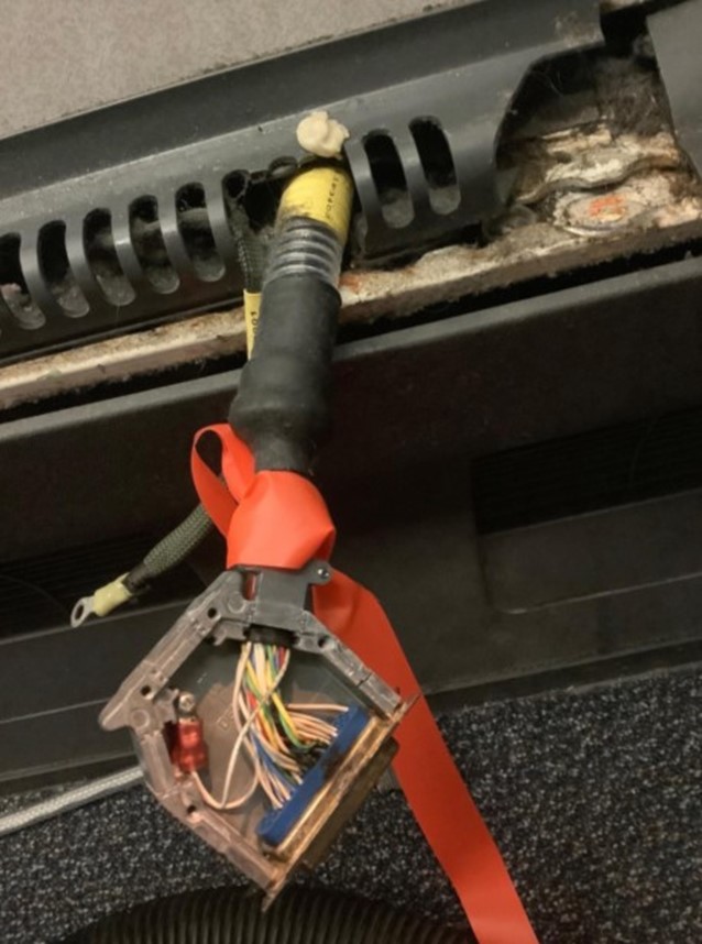
Picture 1 – IFE wiring cannon plug with burnt connections
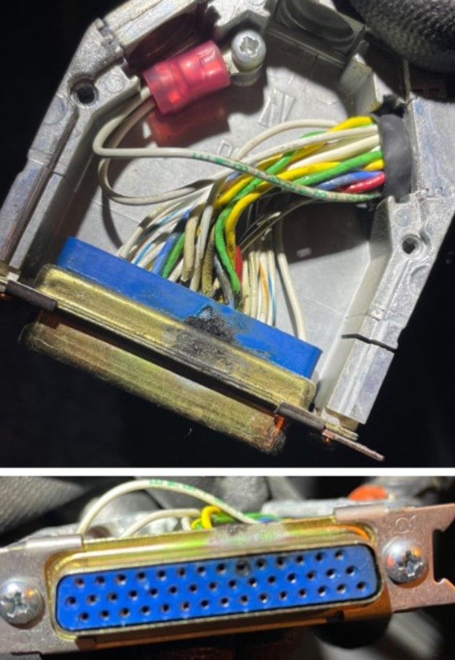
Picture 2 – Close-up of plug with burnt pins
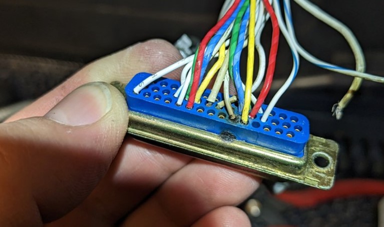
Picture 3 – Plug disassembled, and wire found severed
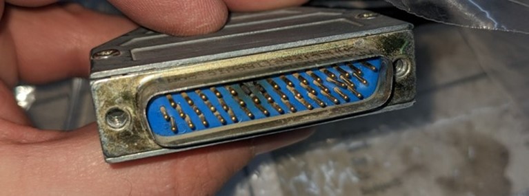
Picture 4 – Close-up of charred pins
MHI RJ Aviation
CL600 2C10 (RJ700) - RJ700/900/1000 – Cockpit window posts cracking
SDR #: 20210422001
Subject:
A crack was discovered in the right-side window post hole when window was removed for replacement.
Transport Canada Comments:
There have been 29 reported events since January 2017 of left and right window posts cracking and 36 reported events since January 2013. The increased number of events over the last 7 years may be due to the fleet aging.
The manufacturer has assessed these cracking events and because the side posts are a fail-safe design have found that there is no immediate safety issue. Non-destructive inspection (NDI) of the posts is included in the manufacture’s maintenance program with the initial inspection interval being 32 000 flight cycles (FC) with a repeat interval of 3200 FC.
Defect history shows the CRJ700/900/1000 window average change interval to be around 23 000 flight hours so there is often an opportunity for a visual inspection prior to the 32 000 FC NDI threshold. Window post cracks are detectable with a detailed visual inspection when the window has been removed. Maintenance personnel should be aware of the potential for post cracking and are advised to perform a detailed visual inspection of the window posts each time a window is removed for replacement.
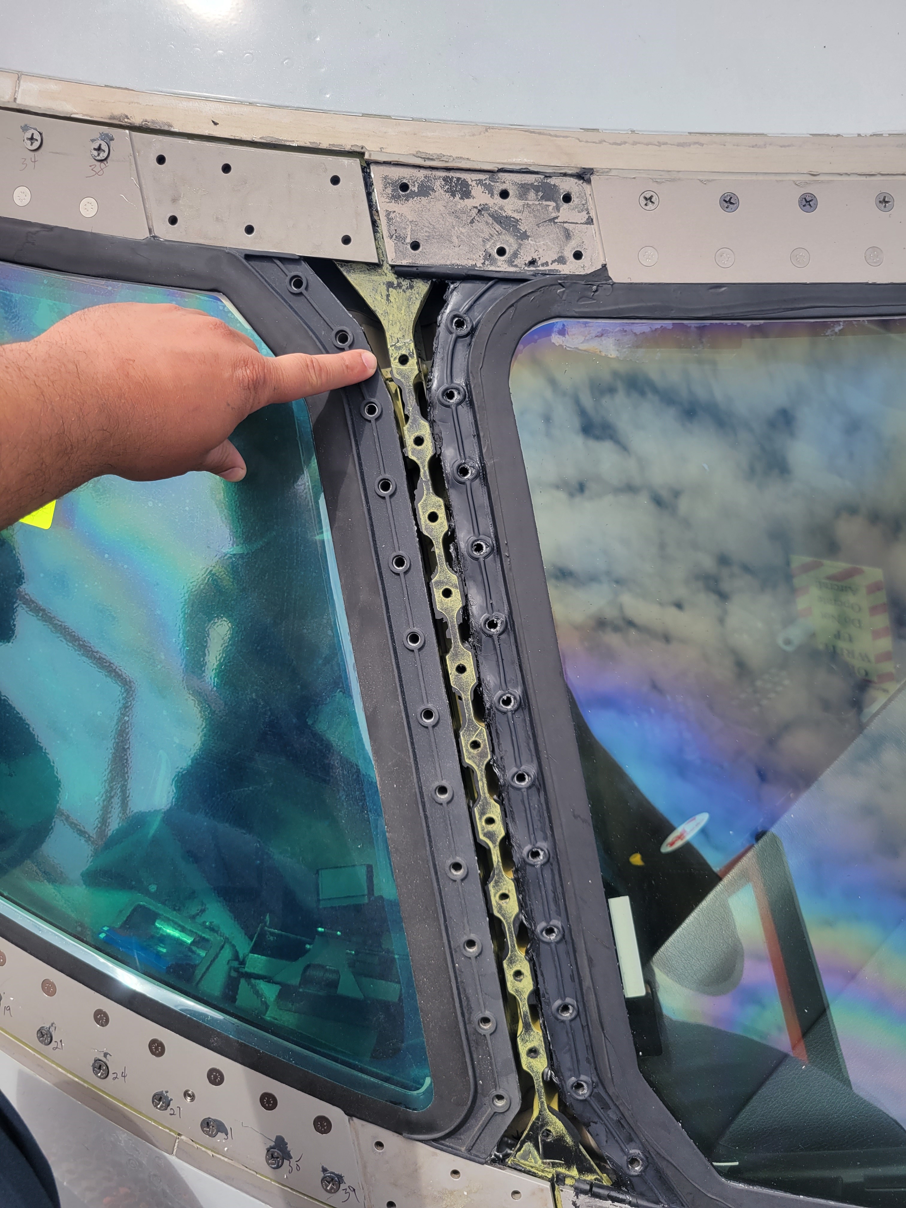
Figure 1: Upper hole cracked on RH side post both sides of hole
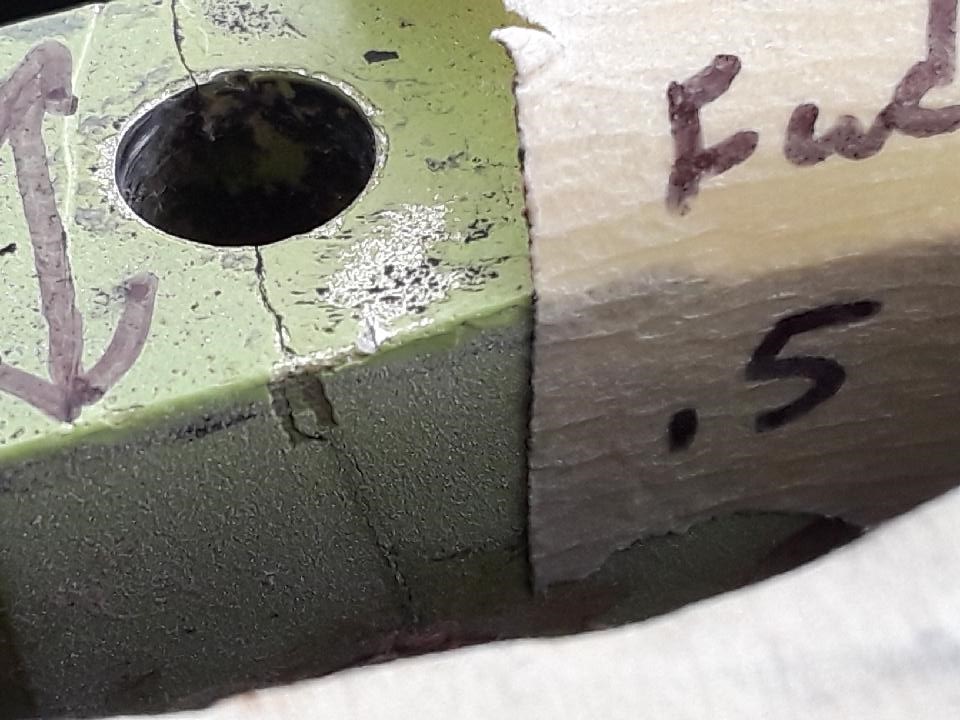
Figure 2: Close up of upper hole crack and shows crack going down through post
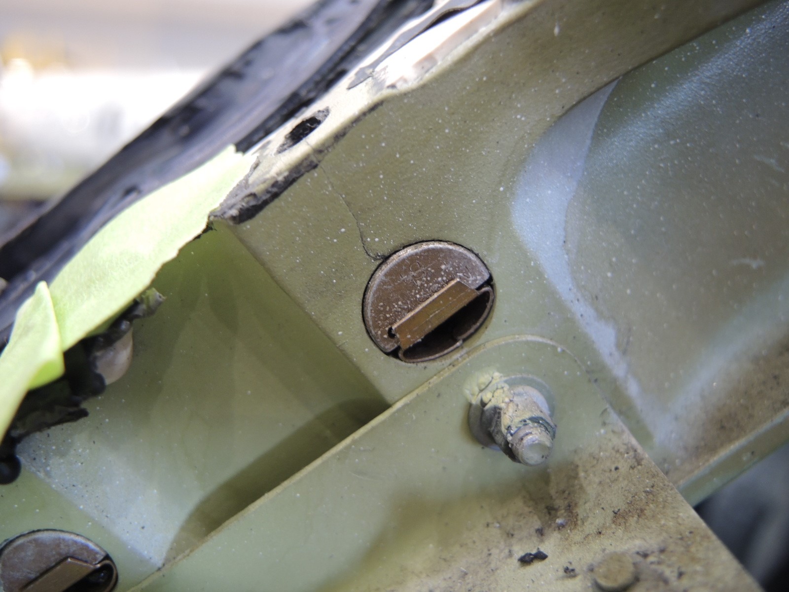
Figure 3: Side view of crack showing the crack going all the way to the nut