Mobile Photometric Measuring Unit
| Issuing Office: | Standards | Document No.: | AC 302-010 |
|---|---|---|---|
| File Classification No.: | Z 5000-34 U | Issue No.: | 01 |
| RDIMS No.: | 5184867-V25 | Effective Date: | 2011-06-30 |
- 1.0 INTRODUCTION
- 2.0 REFERENCES AND REQUIREMENTS
- 3.0 BACKGROUND
- 4.0 RESPONSIBILITIES
- 5.0 MAINTENANCE PROGRAM
- 6.0 SUMMARY
- 7.0 CONTACT OFFICE
1.0 INTRODUCTION
- This Advisory Circular (AC) is provided for information and guidance purposes. It describes an example of an acceptable means, but not the only means, of demonstrating compliance with regulations and standards. This AC on its own does not change, create, amend or permit deviations from regulatory requirements, nor does it establish minimum standards.
1.1 Purpose
- The purpose of this document is to provide guidance for the measurement of high intensity runway edge HIRL, runway centreline, touchdown zone and taxiway centreline lighting for those airports equipped for Category II and III operations to ensure proper photometric measurement is conducted as part of an airport’s system of preventive maintenance of visual aids.
1.2 Applicability
- This document applies to all aerodrome, airport, and heliport operators that provide runway, taxiway lighting systems, aviation lighting manufacturers and installers, Transport Canada Civil Aviation (TCCA) Inspectors, and air navigation service providers. This information is also available to the aviation industry for information purposes.
1.3 Description of Changes
- Not applicable.
2.0 REFERENCES AND REQUIREMENTS
2.1 Reference Documents
-
It is intended that the following reference materials be used in conjunction with this document:
-
Aeronautics Act (R.S., 1985, c. A-2);
-
Part III, Subpart 01 of the Canadian Aviation Regulations (CARs) – Aerodromes;
-
Part III, Subpart 02 of the CARs – Airports;
-
Transport Canada publication, TP 312, 4th Edition – March 1993 – Aerodrome Standards and Recommended Practices (revised 03/2005); and
-
International Civil Aviation Organisations (ICAO) Annex 14 to the Convention on International Civil Aviation, 4th Edition, Vol. 1 & 2, 2004-07-01 – Aerodromes; (all ICAO publications are copyrighted and are available for purchase from ICAO through their website at www.ICAO.int).
-
2.2 Cancelled Documents
-
Not applicable.
- By default, it is understood that the publication of a new issue of a document automatically renders any earlier issues of the same document null and void.
2.3 Definitions and Abbreviations
-
The following abbreviation is used in this document:
- AGL: aerodrome ground lighting.
3.0 BACKGROUND
-
The lighting systems specified in TP 312, 4th edition, section 5.3, are designed to provide the visual aids that pilots need to use for operation of their aircraft safely in all variable weather conditions, by day and by night. To be effective, the characteristics of each visual aid need to be monitored and always properly maintained.
- Photometric measurement of the output of the airside visual aids lighting systems, particularly on runways and taxiways, should be used by the aerodrome operator to verify that the lights are operating to applicable standards and manufacturers’ recommendations as described within their aerodrome’s preventive maintenance plan program.
4.0 RESPONSIBILITIES
-
At an aerodrome operating at night and/or during reduced/low poor visibility conditions lighting is required for active compliance with Part III of the CARs – Aerodromes, Airports, and Heliports.
-
Subsection 602.40(1) of the CARs of the General Operating and Flight Rules says in part “… no person shall conduct a landing or a take-off in a heavier-than-air aircraft at night at an aerodrome unless the aerodrome is lighted in accordance with the aerodrome lighting requirements specified in Part III”. This regulation supports the requirement for aerodrome operators to comply with applicable regulations such as:
-
Aerodromes – Section 301.07 of the CARs; and
-
Airports – Subsection 302.07(1) of the CARs.
-
- It is aerodrome operators’ responsibility to ensure that their airside lighting is correctly installed, inspected and maintained in accordance with published specifications of TP 312, manufacturers’ specifications and recommended maintenance procedures; and that the lighting intensity values are correctly maintained for the service life of the system(s).
5.0 MAINTENANCE PROGRAM
- This document discusses the use of photometric measurement as part of a system of preventive maintenance for runway and taxiway aerodrome visual aids.
5.1 The Need for Maintenance
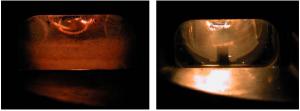
- The performance of lighting at an aerodrome is only as good as the quality of maintenance. The lighting as newly installed eventually degrades through time as the result of lamp aging, rubber deposit, snowplow damage, movement due to jet blast, dirt accumulation and the like. This degradation can easy be seen in Figure 1. Degraded fixture – left; and New fixture – right.
Photo credit: DeWiTec GmbH DALMAS-mobile photometric measurement systemFigure 1: Inpavement light degradation due to aging and rubber deposit
5.2 Visual Inspection
-
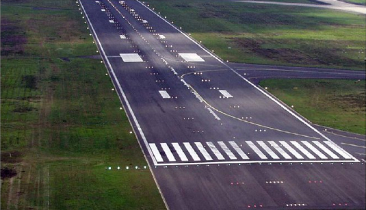
It has been the practice to decide the condition of lighting, partially shown here in Figure 2, through means of visual inspection. That is, when conducting a daily inspection those lights that “appear” dim are listed for repair. However, the ability of a person to visually determine "failure" in relation to degradation is substantially limited.
Photo credit: DeWiTec GmbHFigure 2: Runway lighting
-
Visual inspection to decide the condition of lighting is limited because it is dependent on subjectively comparing one light unit to another. Degradation may not be specific to only one light unit but is generalized to a group of lights. For example, if one considers rubber deposit, then it is likely to take place for the majority of lights in the touchdown zone that are within the view of the inspector. Thus the lights are degraded in unison and a clear comparison cannot be made. Similarly, lamp aging may be generalized to all the lights within a system. Without measurement to objectively decide the performance of the light unit, the inspection cannot accurately assess the facility's condition.
5.3 Standards Reference
-
According the ICAO Annex 14, article 10.4.1 … “A light shall be deemed to be unserviceable when the main beam average intensity is less than 50 percent of the value specified in the appropriate figure in Appendix 2. For light units where the designated main beam average intensity is above the value shown in Appendix 2, the 50 percent value shall be related to that design value.”
-
And further in article 10.4.5: "Recommendation.— Measurement of intensity, beam spread and orientation of lights included in approach and runway lighting systems for a precision approach runway category II or III should be undertaken using a mobile measuring unit of sufficient accuracy to analyze the characteristics of the individual lights."
-
TP 312 standards currently state the below, albeit there is intent to revise this definition to harmonize with that of ICAO Annex 14, article 10.4.1.:
"Light failure. A light shall be considered to have failed when for any reason the average intensity determined using the specified angles of beam elevation, toe-in and spread falls below 50 percent of the specified average intensity.”
-
The addition of "design value", in Annex 14, is of importance in that it addresses system balance. For a particular operational level, the airport may have installed light units whose output is very much in excess of the specified standard. For example, if the standard calls for 20cd and the installed taxiway centreline lights are 100cd, then an imbalance may occur if the lights are maintained only to the standard. A light in this example would be replaced when the output falls below 10cd (50% of standard) yet adjacent lights may have an output in the order of 100cd. Thus the ratio of brightness within the system may be 10:1 rather than the intended 2:1.
- The assessment of the lighting should be done in accordance with the design value.
5.4 Photometric Specification
-
Aeronautical Ground Lights (AGLs) are normally specified by way of an isocandela diagram as shown in Figure 3.
Figure 3: Isocandela diagram for runway centreline light unit
-
The isocandela diagram of Figure 3 is the display as seen by the pilot. That is, directly into the light unit. A profile of the output is shown in Figure 4. The important features for purpose of measurement are the main beam and the 10 and 5% curves.
Figure 4: Light beam
-
Within the main beam it is necessary to figure out the average intensity. This is done by taking measurements on the nodes of a grid as shown in Figure 5. This applies to runway and approach light units for which the isocandela curves are ellipses. For taxiway centreline lights the curves are rectangles, but the principle is the same.
Figure 5: Measurement points within the main beam
-
The average intensity is the sum of the measurement values divided by the number of measurements. In Figure 5 there are 68 points, however, this will change for different lights since the dimensions of the main beam ellipse will also change. Measurement at the lowest point of [0,0] is difficult to get, so this point may be shifted by + 0.5 degrees. Once the average intensity is determined, the individual measured values are checked against the average. The measured values should not be less than the average and not more than 3 times the average. The purpose of these criteria is to ensure a uniform shape of the main beam. That is, there should not be significant low or high parts of the beam in this area.
- For the outer ellipses the values of measured intensity should not be less than the indicated criteria of 10% and 5% of the average within the main beam. The purpose of the outer ellipses is to ensure a minimum available signal outside the main beam.
5.5 Mobile Measurement Units
-
Since it would take too long to manually obtain individually the number of measurements indicated in Figure 5 for each light, mobile measuring units have been developed.
-
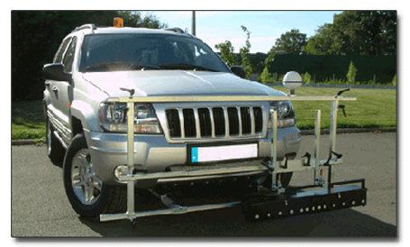
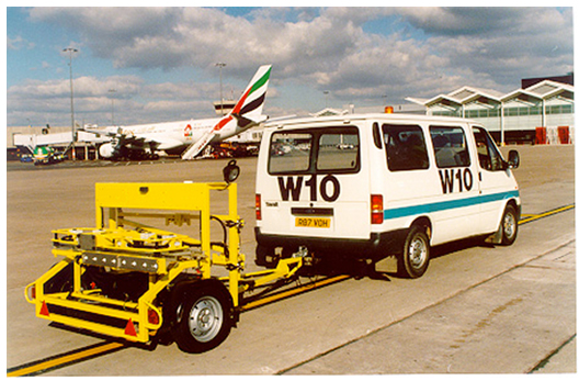
Examples of mobile measurement units are shown in Figures 6 and 7.
Photo credit: GSI Inc.Figure 6: Vehicle Mounted Photocell Array
Photo credit: TMS PhotometricsFigure 7: Trailer version
- Mobile measuring units are usually vehicles that carry a photocell array that is either attached or pulled behind in the form of a trailer. The principle of operation is that the array is brought over the light unit at a fixed distance from the ground so that, as shown in figure 8, a horizontal "cut" is effectively made through the beam, as shown in Figure 8.
Figure 8: Measurement through the beam
-
Following this, a software program, as depicted by Figure 9, converts these measurements made with horizontal movement into an image of the light beam that may be used to make an assessment against the standard or against the design value as appropriate.
Figure 9: Sensors and processed image of the light beam
- Once the measurement information is available, it can be charted as shown in Figure 10 so that the light requiring maintenance attention can be readily identified.
Figure 10: Charting the measurement information
6.0 SUMMARY
-
Airport operators are responsible for ensuring the continued performance of airfield lighting to the stipulated requirements in accordance with Part III of the CARs – Aerodromes, Airports, and Heliports.
- Mobile units are available and which can do rapid measurement the performance of runway and taxiway edge and in pavement light units.
7.0 CONTACT OFFICE
For more information, please contact the appropriate TCCA Regional Office listed at the following address:
https://tc.canada.ca/en/corporate-services/regions
Suggestions for amendment to this document are invited, and should be submitted via the Transport Canada Civil Aviation Issues Reporting System (CAIRS) at the following Internet address: https://tc.canada.ca/en/aviation/civil-aviation/civil-aviation-issues-reporting-system-cairs or by e-mail at: CAIRS_NCR@tc.gc.ca.
[original signed by Ron Carter for]
Jacqueline Booth
A/Director, Standards
Civil Aviation
Transport Canada
Transport Canada documents or intranet pages mentioned in this document are available upon request.
AC 302-010 - Mobile Photometric Measuring Unit
(PDF, 757 KB)


