Table of Contents
- 1.0 Introduction
- 2.0 Definitions
- 3.0 Background
- 4.0 Summary of Requirements
- Part 1 - General
- Part 2 - Test and Performance Specifications for Type Approval of Oil Content Meters for Bilge Alarms
- 10.0 General Provisions
- 11.0 Test specifications
- 12.0 Calibration of Meter
- 13.0 Calibration Test, Contaminant and colour test, Sample pressure or flow test, Shut off tests, Utilities supply variation test, Calibration and zero drift test, and Response time test
- 14.0 Issuance of Certificate of Type Approval
- Part 3 - Method of Determination of Oil Content
- Part 4 - Testing Facilities and Laboratories
- Schedule 1
- Schedule 2
- Schedule 3
- Schedule 4
1.0 Introduction
- 1.1 The Oil Pollution Prevention Regulations that were introduced in 1993 permitted a ship en route in the inland waters of Canada to discharge from its ship’s machinery space an undiluted effluent containing no cargo oil, chemicals, or any substances introduced for the purpose of circumventing the Regulations, providing an alarm and a discharge stopping device were activated when the oil content in the effluent exceeded 5 ppm . To achieve this criteria required the fitting of a “bilge alarm” capable of detecting and measuring 5 ppm of oil in the oil/water effluent mixture.
- 1.2 The Regulations for the Prevention of Pollution from Ships and for Dangerous Chemicals that replace several regulations under the Canada Shipping Act, including the Oil Pollution Prevention Regulations, retain the provision to permit 5 ppm discharges in Canadian inland waters. The requirements of the Regulations and of this publication have been updated to account for the International Maritime Organization’s (IMO) ‘Revised Guidelines and Specifications for Pollution Prevention Equipment for Machinery Space Bilges of Ships’, Resolution MEPC .107(49). Systems fitted on ships with 5 ppm bilge alarms that were approved under the Oil Pollution Prevention Regulations and Resolution MEPC .60(33) may continue to be used.
- 1.3 Comments and suggestions for the improvement of this Standard should be forwarded to:
Director, Operations and Environmental Programs
Marine Safety, Transport Canada
Tower C, Place de Ville, 330 Sparks Street
Ottawa, Ontario K1A 0N8
(Fax No. 613-993-8196). - 1.4 Information on the ISO can be obtained from:
Standards Council of Canada
270 Albert Street, Suite 200
Ottawa, Ontario K1P 6N7
Telephone: (613) 238-3222
Fax: (613) 569-7808
2.0 Definitions
- 2.1 “accredited testing facility” means a testing laboratory that has been accredited in accordance with the requirements of ISO/IEC 17025, as being capable of carrying out the test procedures determined by this Standard;
- 2.2 “accredited testing laboratory” means a laboratory that is accredited in accordance with ISO/IEC 17025 as being capable of making a successful determination of oil content in accordance with IMO Resolution MEPC .107(49), Part 4;
- 2.3 “bilge alarm” means an oil content meter with associated alarm;
- 2.4 “ ISO/IEC 17025” means ISO/IEC 17025 “General requirements for the competence of testing and calibration laboratories”, latest edition;
- 2.5 “ IMO ” means International Maritime Organization;
- 2.6 “ ISO ” means International Standards Organization;
- 2.7 “ MEPC ” means the Marine Environment Protection Committee of the IMO ;
- 2.8 “ ppm ” means parts per million, by volume;
- 2.9 “Resolution MEPC .107(49)” means the IMO recommendation entitled Revised Guidelines and Specifications for Pollution Prevention Equipment for Machinery Space Bilges of Ships.”
3.0 Background
- 3.1 The requirement for bilge alarms for ships in Canadian inland waters are set out in sections 17, 28 and 187 of the Regulations for the Prevention of Pollution from Ships and for Dangerous Chemicals (the Regulations).
4.0 Summary of Requirements
- 4.1 The approval requirements for bilge alarms specified in this Standard are summarized as follows:
- In addition to having undergone tests and obtained a Certificate of Type Approval in accordance with Resolution MEPC .107(49) of the IMO , for a 15 ppm bilge alarm, the bilge alarm shall comply with the requirements of this Standard to enable it to be used as a 5 ppm bilge alarm in Canadian inland waters.
- Where an apparatus has undergone a particular test or requirement in order to qualify as a 15 ppm bilge alarm in accordance with IMO Resolution MEPC .107(49), the apparatus need not undergo an identical test or requirement for the purposes of this Standard.
- The bilge alarm shall be tested for type approval in accordance with Part 2 of this Standard.
Part 1 - General
5.0 General Provisions
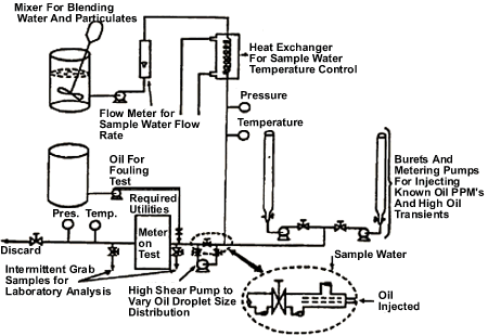
- 5.1 Providing grab samples are taken, and calibration, cleansing and testing procedures are sequenced as detailed in this specification, testing equipment shown in Figure 2 in Schedule 1 may be used in lieu of the testing equipment shown in Figure 1.
6.0 Application
- 6.1 This Standard applies:
- to installations fitted to ships, the keels of which are laid, or which are at a similar stage of construction, on or after January 1, 2005; and
- to new installations fitted on or after January 1, 2005 to ships, the keel of which were laid or which were at similar stage of construction before January 1, 2005.
7.0 Technical Specifications for "Bilge Alarms"
- 7.1 This specification refers to bilge alarms that have a meter with associated alarm, that are capable of detecting and measuring 5 ppm or less of oil in a ship’s machinery space bilge water overboard discharge.
- 7.2 It shall be a robust and practical instrument suitable for shipboard use.
- 7.3 It shall resist corrosion in the conditions of the marine environment and shall be compatible with the liquids that it will monitor.
- 7.4 It shall not contain or use any substance of a dangerous nature, unless adequate arrangements are provided to eliminate any hazards introduced thereby.
- 7.5 It shall, if intended to be fitted in locations where flammable atmospheres may be present, comply with the relevant safety regulations for such spaces. Any electrical equipment that is part of the meter shall be placed in a non-hazardous area, or shall be certified as safe for use in a hazardous atmosphere. Any moving parts that are fitted in hazardous areas shall be arranged so as to avoid the formation of static electricity.
- 7.6 The response time of the 5 ppm Bilge Alarm, that is, the time which elapses between an alteration in the sample being supplied to the 5 ppm Bilge Alarm and the ppm display showing the correct response, shall not exceed 5 seconds.
- 7.7 A ppm display shall be provided. The ppm display should not be affected by emulsions and/or the type of oil given that the test fluid detailed in paragraph 1.2.4 of Part 1 of the annex to MEPC .107(49) is deemed to represent a mixture that may be expected in the machinery space bilges of a ship. It should not be necessary to calibrate the Bilge Alarm on board ship, but onboard testing according to the manufacturers instructions shall be permitted. The accuracy of the meter shall be such that the reading will represent within +/- 3 ppm , the actual oil content of the sample being tested.
- 7.8 The Bilge Alarm shall be fitted with an electrical/electronic device which should be pre-set by the manufacturer to activate when the effluent exceeds 5 ppm and shall do so with an accuracy of +/- 1 ppm . This shall also operate automatically if at any time the Bilge Alarm should fail to function, require a warm-up period or otherwise be de-energized. The accuracy the Bilge Alarm shall remain within the above limits despite the presence of contaminants other than oil, and the power supply varying by 10% from the design value, i.e. inrespect of electricity, compressed air, etc.
- 7.9 It is required that a simple means be provided aboard ship to check on instrument drift, repeatability of the instrument reading, and the ability to re-zero the instrument.
- 7.10 The Bilge Alarm shall record date, time and alarm status, and operating status of the oil filtering equipment. The recording device shall also store data for at least 18 months and shall be able to display or print a protocol for official inspections as required. In the event the Bilge Alarm is replaced, means shall be provided to ensure the data recorded remains available on board for 18 months.
- 7.11 The following items shall be included:
- every access of the Bilge Alarm beyond the essential requirements of paragraph 7.8 requires the breaking of a seal; and
- the Bilge Alarm shall be so constructed that the alarm is always activated whenever clean water is used for cleaning or zeroing purposes.
- 7.12 The accuracy of the Bilge Alarm shall be checked at International Oil Pollution Prevention Certificate renewal surveys or Canadian Oil Pollution Prevention Certificate renewal surveys and shall be done according to the manufacturers instructions. Alternatively the unit may be replaced by a calibrated Bilge Alarm. The calibration certificate for the Bilge Alarm, certifying date of last calibration check, shall be retained onboard for inspection purposes. The accuracy checks can only be done by the manufacturer or persons authorized by the manufacturer.
- 7.13 The Bilge Alarm shall comply with the test and performance requirements of Part 2 of this Standard.
8.0 Specification for Type Approval of Pollution Prevention Equipment
- 8.1 Production Model: A production model bilge alarm for which the approval will apply shall be identical to the equipment type-tested in accordance with the test and performance specifications contained in Part 2 of this Standard.
9.0 Approval and Certification Procedures
- 9.1 Apparatus for which a Certificate of Type Approval for 15 ppm has been issued in accordance with IMO Resolution MEPC .107(49) and which in every particular also fulfils the relevant requirements of these specifications, may be approved for use in ships in Canadian inland waters under section 12 of the Regulations.
- 9.2 Apparatus that meets the requirements of paragraph 9.1 may be issued with a Canadian Certificate of Type Approval in accordance with section 14 of this Standard.
- 9.3 A copy of the Certificate of Type Approval for the oil bilge alarm shall be carried on board each ship that is fitted with such equipment.
Part 2 - Test and Performance Specifications for Type Approval of Oil Content Meters for Bilge Alarms
10.0 General Provisions
- 10.1 Calibration and testing shall be carried out using a light distillate fuel oil having a relative density of 0.83 at 15° C .
- 10.2 These Test and Performance Specifications relate to Bilge Alarms. In addition, the electrical and electronic section of these systems shall be in accordance with the Specifications for Environmental Testing contained in Part 3 of IMO Resolution MEPC .107(49).
- 10.3 The Bilge Alarm being tested shall comply with all the relevant requirements of the technical specifications contained in section 7.0 of this Standard.
11.0 Test specifications
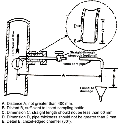
- 11.1 The sampling arrangement for the test rig should be such that a representative homogeneous sample is obtained under all conditions of operation and under all operational proportions of oil content. The sample should be obtained from the full flow through the Bilge Alarm, but when this is impracticable the sampling arrangements shown in Figure 3 in Schedule 1 shall be used. Special care should be given to this stage of the process and the validity of the resultant findings.
- 11.2 During the various tests, the response time of the Bilge Alarm shall be checked and it shall be noted whether alarms operate adequately when a pre-stated threshold is exceeded.
- 11.3 A diagrammatic arrangement of a test facility for evaluating the performance of the Bilge Alarm is given in Figure 2. The accuracy of the Bilge Alarm shall be determined by comparing its readings against a known flow of Test Fluid injected into a known flow of water. The grab samples taken shall be analysed in a laboratory by the methods specified section 15 of this Standard. The results of the laboratory analysis shall be used for correction and to indicate sampling and test equipment variability. The water flow rate shall be adjusted so that the entire Test Fluid-water flow passes through the Bilge Alarm, except the intermittent grab sample stream. Special care should be given to keep, continuously, a constant Test Fluid content in the water that flows into the Bilge Alarm. The metering pumps should be adjusted to deliver a nearly continuous quantity of Test Fluid. If Test Fluid injection becomes intermittent at low concentrations, the Test Fluid may be pre-mixed with water to provide continuous flow. The Test Fluid injection point should be immediately up-stream of the Bilge Alarm inlet to minimize time lags.
12.0 Calibration of Meter
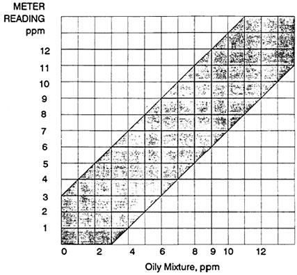
- 12.1 The oil content meter shall be calibrated at 0, 2, 4, 6, and 9 ppm . A complete calibration curve shall be provided in the format shown in Figure 4 in Schedule 3. The calibration procedure shall be conducted as follows.
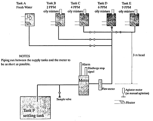
- 12.2 Four tanks for pre-mixed oily mixtures, one tank of fresh water and one settling tank for drainage, with associated piping and testing equipment, shall be provided in a testing arrangement as shown in Figure 1 in Schedule 1.
- 12.3 With all valves closed the tank shall be filled with liquid, as appropriate.
- 12.4 Valve A shall be opened and fresh water shall be allowed to flow through the meter for 5 minutes, at which time the reading on the meter shall be noted and the point shall be marked on the calibration diagram. This point should be the zero point on the meter scale. If this is not so, corrective action shall be taken. Valve A shall be shut.
- 12.5 Valve B shall be opened and the 2 ppm oily mixture shall be allowed to flow through the meter for 5 minutes, at which time the meter reading point shall be marked on the calibration diagram. Valve B shall be closed.
- 12.6 Valve A shall again be opened and fresh water shall be allowed to flow through the meter. The flow of the cleansing water shall be continued until the meter reading has been zeroed for 5 minutes. Valve A shall then be closed.
- 12.7 Valve C shall be opened and the calibration operation shall be continued using an identical calibration and cleansing sequences to those described in paragraphs 12.5 and 12.6.
- 12.8 The calibration point for the 6 ppm and 9 ppm oily mixtures shall be plotted, using an identical calibration and cleansing sequence to those described in paragraphs 12.5 and 12.6.
- 12.9 The five calibration points shall be joined in order to establish the calibration curve.
13.0 Calibration Test, Contaminant and colour test, Sample pressure or flow test, Shut off tests, Utilities supply variation test, Calibration and zero drift test, and Response time test
- 13.1 The Calibration Test, Contaminant and colour test, Sample pressure or flow test, Shut off tests, Calibration and zero drift test, and the Utilities supply variation test, as described in IMO Resolution MEPC .107(49) are accepted for the purposes of the Standard and need not be repeated.
- 13.2 In addition to The Response time test described in
MEPC
.107(49) the following shall be carried out:
The response time is to be taken for the Bilge Alarm to give an alarm at 5 ppm oil concentration after the supply to the Bilge Alarm is changed from clean water to oily water having a concentration of more than 5 ppm . The response time of the Bilge Alarm should be as short as possible and in all cases shall be such that the closing of an associated automatic stopping device would occur no longer than 20 seconds from the time of changing from clean water to oily water having a concentration of more than 5 ppm .
14.0 Issuance of Certificate of Type Approval
- 14.1 Following successful calibration and the procedures required by section 13.0 as applicable, the equipment shall be considered to have passed the test.
- 14.2 A copy of the test data and the results of the test shall be forwarded to: The Manager, Environmental Protection, Marine Safety, Transport Canada Ottawa, Ontario K1A 0N8.
- 14.3 The test results shall include the test laboratory’s analyses of the five calibration test samples and the one alarm test sample, in the general format shown in the Table in Schedule 2.
- 14.4 If satisfied with the test data and test results, the Manager, Environmental Protection, Marine Safety may cause a Certificate of Type Approval to be issued.
Part 3 - Method of Determination of Oil Content
15.0 General
- 15.1 The method for the determination of oil content of samples taken for the purposes of this Standard, shall be in accordance with the requirements of IMO Resolution MEPC .107(49), Part 4.
Part 4 - Testing Facilities and Laboratories
16.0 Accredited Testing Facility
- 16.1 It is recommended that testing carried in accordance with the requirements of this Standard should be conducted at an accredited testing facility. Schedule 4 lists facilities that have been accredited.
17.0 Accredited Testing Laboratory
- 17.1 It is recommended that the determination of the oil content of samples taken for the purposes of this Standard should be conducted at an accredited testing laboratory.
Schedule 1
Figure 1- Diagrammatic Arrangements of Test Facilities
Figure 2 - Alternate Diagrammatic Arrangements of Test Facilities
Figure 3 - Diagram of Sampling Arrangements
Schedule 2
Test Results
Schedule 3
Figure 4 Bilge Alarm Calibration Graph Format
Schedule 4
List of Accredited Testing Facilities
- ERA Technology Ltd.
Cleeve Road
Leatherhead
Surrey KT22 7SA
England
Tel: 0372 374151
Fax: 0372 374496
Contact: Mr. John Billing
Materials Technology Department - Peacock – Weir Naval Engineering Testing Establishment Lasalle, P.Q.


