Table of Contents
- 1. Context
- 2. Marine acts and regulations
- 3. Stability
- 4. Construction
- 5. Machinery installation
- 6. Bibliography
1. Context
1.1. Introduction
This guide has been prepared to help applicants reach the competency level required to obtain a Fourth-class engineer certificate with STCW endorsement. These requirements are set out in Table A-III/1 of the STCW Code. The competencies concerned here are:
- Monitor compliance with legislative requirements;
- Maintain seaworthiness of the ship.
Applicants who answer the questions in annexes B and C of TP-13721, Training Record Book Requirements for Applicants to the Fourth-class Certificate, instead of taking approved training must be familiar with the Canada Shipping Act, 2001; the Prevention of Pollution From Ships and for Dangerous Chemicals Regulations; Ballast Water Control and Management Regulations; and Environment Response Regulations. These regulations all stem from the Canada Shipping Act, 2001. Applicants must also be familiar with the MARPOL and SOLAS conventions.
Applicants must also have access to books on ship stability and naval architecture.
Applicants must anticipate 60 hours of work to complete the questionnaire. The part on the acts and regulations is estimated to require 20 hours of work, while the part on stability and construction can take up to 40 hours of work. Once the questionnaire has been completed, it must be presented to a Marine Safety examiner for evaluation.
1.2. Objectives
This study guide is designed to ensure that applicants acquire basic knowledge of the following subjects, which is relevant for their future employment:
- Canadian acts and regulations governing pollution prevention on the Great Lakes and other Canadian inland waters;
- IMO conventions related to protection of the marine environment and the safety of life at sea;
- Use of a ship’s hydrostatic tables and stability data;
- Fundamentals of watertight integrity and actions to be taken in the event of partial loss of intact buoyancy;
- Principal structural members of a ship.
2. Marine acts and regulations
2.1. Canadian laws and regulations
2.1.1. Acts and regulations
Almost all aspects of the marine transport industry are highly regulated. The most important legislation governing marine transport includes the Pilotage Act, Marine Transportation Security Act, Navigable Waters Protection Act and Canada Shipping Act, 2001 to name a few. The Canada Shipping Act, 2001 is the umbrella act for marine activities and regulates the largest number of aspects.
Implementation of many of the provisions of the CSA 2001 is provided by the different regulations. These regulations are called subordinate legislation because they derive from the related act to which they refer. That is why the expression "Canada Shipping Act, 2001 and its regulations" is often used.
There are different regulations that are subordinate to various acts that apply to marine transport. They include the Marine Personnel Regulations, Prevention of Pollution from Ships and for Dangerous Chemicals Regulations; Ballast Water Control and Management Regulations; Environment Response Regulations; Small Vessel Regulations; Load Line Regulations; as well as the Canada Labour Code, to name a few.
2.1.2. Adoption process for Canadian acts and regulations
To better understand the scope of the different legislative texts, it is important to have some basic knowledge of the legislative process in Canada.
In Canada, bills become acts by following a multi-step process.
Bills are introduced either in the House of Commons or the Senate, depending on the situation, where they pass through the first, second and third reading. Once the third reading has been passed, the bill is sent to the Senate to be examined and adopted by the senators. The last step is Royal Assent, which is given by the Governor General of Canada in the Queen's name. The bill becomes law at this point.
Regulations to implement the acts also follow a clearly defined procedure called the regulatory process. Draft regulations must go through the following steps:
2.1.2.a. Conception and development
This step is to demonstrate the need for introducing regulations and to determine the main consequences.
2.1.2.b. Drafting of a regulation
Developing draft regulations may take some time depending on the stakeholders involved and the impact of the regulations, and it must follow the applicable regulatory policy.
2.1.2.c. Review and preliminary assessment
In this step, the regulations are carefully examined by the authorized bodies, which are the Clerk of the Privy Council and the Deputy Minister of Justice. This step verifies that the regulations are not in conflict with another act, for instance.
2.1.2.d. Ministerial approval for pre-publication
2.1.2.e. Pre-publication review
This step is carried out by the Regulatory Affairs and Orders in Council (RAOIC) Secretariat and the Treasury Board.
2.1.2.f. Pre-publication in the Canada Gazette, Part I
This step includes a comment period to allow various interest groups to comment on the regulations one last time.
2.1.2.g. Preparation of final regulatory proposal
The Department of Justice presents the final bill to Treasury Board, including the amendments made subsequent to the comments received.
2.1.2.h. Final review by the RAOIC and the Treasury Board
2.1.2.i. Making, registering, publishing in the Canada Gazette, Part II, and distributing regulations
The regulations can be enforced after this step.
2.1.2.j. Parliamentary review
Enforcement of the regulations is monitored by the Standing Joint Committee for the Scrutiny of Regulations.
2.1.3. Implementation of international conventions to which Canada is a party
World-wide, the International Maritime Organization (IMO) is responsible for developing various international conventions related to marine transport. Canada is a signatory to some of these conventions. The best known ones include the International Convention for the Prevention of Pollution from Ships (MARPOL), the International Convention for the Safety of Life at Sea (SOLAS) and the International Convention on Load Lines. These international conventions apply to the signing countries only insofar as they incorporate the content of these texts into their own legislation. If the countries do not incorporate the content of the conventions, they do not have the force of law. That is why many Canadian regulations refer to the international conventions. Furthermore, sometimes Canada has not ratified certain sections of the conventions, either because they are too complex to apply at this point, or because the country's requirements are already stricter than the international standards. This is the case for the MARPOL Convention, whereas the entire SOLAS Convention applies. Implementation of the International Convention on Load Lines is assured through Canadian regulations governing load lines made under the CSA 2001.
2.1.4. Canadian Regulations made pursuant to the Canada Shipping Act, 2001
As mentioned above, the CSA 2001 is one of the acts that governs marine transport in Canada. The CSA 2001 is linked to several different regulations that followed from it and ensured the application of more specific aspects of the Act. Some of them are presented below.
2.1.4.a. Prevention of Pollution from Ships and for Dangerous Chemicals Regulations (Air Pollution Regulations):
The MARPOL Convention contains provisions on air pollution from atmospheric emissions from ships. Because Canada has not ratified this MARPOL Annex, the requirements in the Canadian Air Pollution Regulations apply.
The regulations presently govern only the colour of the smoke (density indicator) emitted by ships while they are in Canadian waters within one mile of land.
The authorized smoke densities are set out in the regulations and are given as a percent of space that is black. The Department of Transport Smoke Chart or a comparable chart is used, upon which fine black dots or lines represent these percentages of black space.
A ship that is in the regulation area may thus not emit smoke of a density greater than the one authorized by the regulations unless one of the exceptional cases below applies:
- New fires being lit;
- Fires are being cleaned or soot is being blown and the ship is not underway;
- The ship is being laid up;
- A breakdown has affected the combustion equipment;
- It is necessary, because of navigational difficulties, to force the combustion equipment.
In these situations, the emission of smoke is permitted if, and only if, all practicable precautions are taken to minimize the emission of smoke.
2.1.4.b. Prevention of Pollution from Ships and for Dangerous Chemicals Regulations (Pollutant Substances Pollution Prevention Regulations)
As mentioned earlier, the key regulatory document concerning the prevention of pollution by ships is the MARPOL Convention. Canada has incorporated the provisions of the international convention governing pollutant substances under various sections of the CSA 2001.
2.1.4.c. Prevention of Pollution from Ships and for Dangerous Chemicals Regulations (Pollutant Discharge Reporting Regulations)
In Canada, control of the discharge of pollutant substances at sea is governed by the Pollutant Discharge Reporting Regulations, which are made under the CSA 2001.
These regulations apply to Canadian ships in all waters and to ships other than Canadian ships in waters under Canadian jurisdiction, including a shipping safety control zone prescribed under subsection 11(1) of the Arctic Waters Pollution Prevention Act.
Some ships are exempted from these regulations. They are warships, naval auxiliary ships and other ships that are owned or operated by a state and used only on government non-commercial service.
These regulations require that in the case of a discharge or the probability of a discharge of a pollutant, the master of the ship shall make a report on the incident. If for any reason the master of the ship does not make the report, the owner of the ship must make the report upon being informed of the situation.
2.1.4.d. Prevention of Pollution from Ships and for Dangerous Chemicals Regulations (Oil Pollution Prevention Regulations) :
These regulations govern the handling, carriage and storage of oil on board ships. They include a list of the documents that must be kept on ships that carry oil either as cargo or as fuel.
The Regulations also govern transfer operations on ships related to the following aspects:
- Communications;
- Lighting;
- Transfer conduits;
- Reception facility and standard discharge connections;
- Supervision of transfer operations on board ships;
- Duties of transfer operations supervisors on board ships;
- Emergencies.
The Oil Record Book is one of the main pieces of documentation to have on board at all times on ships governed by the Regulations.
The form of the Oil Record Book (Parts I and II) is set out in Appendix III to Annex I of the MARPOL Convention.
The Oil Record Book shall be kept on board for a period of three years after the last entry has been made and, at any time during the period it is on board, shall be made available for inspection.
The Oil Record Book is divided into two parts:
-
Part I
Operations in machinery spaces. This part of the Oil Record Book is mandatory for every oil tanker of 150 tons gross tonnage or more and any other ship of 400 tons gross tonnage or more that carries oil as fuel or as cargo.
-
Part II
Operations concerning cargo and ballast. This part of the Oil Record Book must be kept on board by every oil tanker of 150 tons gross tonnage or more.
In addition to the Oil Record Book, the Oil Pollution Prevention Regulations require that every oil tanker of 150 tons gross tonnage or more and any other ship of 400 tons gross tonnage or more that carries oil as fuel or as cargo shall keep on board an English or French version of:
- One of the following documents, namely:
- a Canadian Oil Pollution Prevention Certificate, where the ship is a Canadian ship that is engaged in voyages exclusively in waters under Canadian jurisdiction;
- an International Oil Pollution Prevention Certificate, where the ship is
- a Canadian ship engaged in voyages that do not take place exclusively in waters under Canadian jurisdiction, or
- a ship, other than a Canadian ship, that is registered in a state that is a signatory to the Pollution Convention and that is engaged in voyages in waters under Canadian jurisdiction, and
- a Certificate of Compliance, where the Pollution Convention does not apply to the ship and the ship is engaged in voyages in waters under Canadian jurisdiction;
- A Type Test Certificate, if applicable, for
- a 100 ppm oily-water separator or 15 ppm oil filtering equipment,
- a process unit,
- an oil content meter (machinery spaces),
- an oil content meter (cargo spaces of oil tankers), and
- an oil-water interface detector (oil tankers);
- An equipment operation manual for
- an oil discharge monitoring and control system (oil tankers), and
- a crude oil washing system (in the case of a crude oil tanker of 20,000 Dwt or more);
- The information and data referred to in Regulations 25(5)(a) and (b) of Annex I (oil tankers).
2.1.4.d.(i) Mandatory retention equipment in case of leaks
The Prevention of Pollution from Ships and for Dangerous Chemicals Regulations (Oil Pollution Prevention Regulations) also contain a section setting out the requirements that apply to ship construction and mandatory equipment. One of the specific requirements in the Regulations concerns containers and enclosed deck areas for bunkering operations. All ships of 100 tons gross tonnage or more shall be equipped with a container or an enclosed deck area that is capable of retaining oil leaked or spilled during bunkering of fuel or bulk lubricating oil.
The minimum capacity of this retention equipment is:
- not less than 0.08 m3 for ships of less than 400 tons gross tonnage;
- not less than 0.16 m3 for ships of 400 tons gross tonnage or more.
There are some exemptions to the Regulations. Ships fitted with an overflow system that prevents oil from discharging onto the open deck and ships that usually fill their bunkers from a truck that is equipped with a bunkering hose that has an inside diameter of 51 mm or less and employs an automatic shut-off nozzle are exempted from this part of the regulations governing retention equipment.
2.1.4.d.(ii) Oil and oily mixture discharges
Part III of the Oil Pollution Prevention Regulations is entitled Oil and Oily Mixture Discharges. It sets out the general prohibitions and exceptions concerning the discharge of such substances.
Generally, the application part of the Regulations states: "No oil or oily mixture shall be discharged from a ship in waters under Canadian jurisdiction." Waters under Canadian jurisdiction are divided into different zones that are accompanied by different restrictions concerning oil discharges.
Waters under Canadian jurisdiction
The territorial sea of Canada consists of a belt of sea that has as its inner limit the baselines described in section 5 and as its outer limit
- subject to paragraph (b), the line every point of which is at a distance of 12 nautical miles from the nearest point of the baselines; or
- in respect of the portions of the territorial sea of Canada for which geographical coordinates of points have been prescribed pursuant to subparagraph 25(a)(ii), lines determined from the geographical coordinates of points so prescribed.
Canadian waters
The exclusive economic zone of Canada is adjacent to the territorial sea of Canada that has as its inner limit the outer limit of the territorial sea of Canada and as its outer limit
- The line every point of which is at a distance of 200 nautical miles from the nearest point of the baselines of the territorial sea of Canada, or, in respect of a portion of the exclusive economic zone of Canada for which geographical coordinates of points have been prescribed pursuant to subparagraph 25(a)(iii), lines determined from the geographical coordinates of points so prescribed.
- Internal waters
The internal waters of Canada consist of the waters on the landward side of the baselines of the territorial sea of Canada. - Division I waters
Division I waters include fishing zones 1, 2 and 3 and those internal waters that are not within a shipping safety control zone. - Division II waters
The territorial sea and portions of fishing zones 4, 5 and 6 that are not within a shipping safety control zone. - Inland waters
All the rivers, lakes and other navigable fresh waters within Canada, and includes the St. Lawrence River as far seaward as a straight line drawn- from Cap des Rosiers to West Point Anticosti Island, and
- from Anticosti Island to the north shore of the St. Lawrence River along the meridian of longitude sixty-three degrees west.
The following concepts must also be considered:
- Shipping safety control zone
The areas of arctic waters shown in Schedule II and described in the zones set out in Schedule I of the Shipping Safety Control Zones Order are prescribed as shipping safety control zones. - Fishing zones 1, 2 and 3
Fishing zones of Canada are the marine areas adjacent to the coast of Canada designated as such by the Oceans Act and the Fishing Zones of Canada (Zones 1, 2 and 3) Order. - Special areas
As mentioned in the MARPOL Convention (see the section about Annex I of MARPOL).
Obviously, an outright ban is lifted if a ship is in an extreme situation where the discharge of oil is unavoidable or necessary for maintaining the ship's stability, for instance. Prevention of Pollution from Ships and for Dangerous Chemicals Regulations sets out the following exceptions:
- A discharge is necessary for the purpose of saving lives or preventing the immediate loss of a ship;
- A discharge occurs as a result of an accident of navigation in which the ship or its equipment is damaged, unless the accident occurs as a result of an action that is outside the ordinary practice of seamen;
- Minimal and unavoidable leakage occurs due to the operation of an underwater machinery component;
- A discharge is made for the purpose of scientific research into pollution abatement or control in accordance with permission granted there for by the competent authority.
Concretely, in a normal situation, no more than 5 ppm of an oily mixture may be discharged from a ship in Division I waters if:
- The ship is making way;
- No oily mixture originates in cargo pump room bilges or is mixed with oil cargo residues;
- The discharge is processed through oil filtering equipment that produces an undiluted effluent that has an oil content of no more than 15 ppm and it triggers an alarm and a discharge stopping device as soon as:
- the effluent exceeds 5 ppm where discharged in inland waters of Canada, or
- 15 ppm where discharged in fishing zones 1, 2, 3 or in those internal waters that do not include inland waters of Canada.
- The discharge does not contain chemicals or any other substance introduced for the purpose of circumventing the detection of concentrations of oil that exceed the oil content limits specified in these regulations.
2.1.4.d.(iii) Emergency plan
If an accident occurs despite all the precautions mentioned, the most important thing is the ability to react rapidly and effectively. That is why the Prevention of Pollution from Ships and for Dangerous Chemicals Regulations require that ships have shipboard oil pollution emergency plans.
The purpose of such plans is to enable the master and crew of the ship to take all the necessary measures to minimize or rectify the effects of an emergency situation that could arise during an oil transfer operation.
The emergency plan must be approved by the Department of Transport. It must also be kept on board every oil tanker of 150 tons gross tonnage or more and other ships of 400 tons gross tonnage or more in waters under Canadian jurisdiction.
2.2. International laws and regulations, IMO conventions
The different countries that have signed the international conventions agree to comply with the requirements of the conventions by integrating them into their legislation.
Among the international conventions to which Canada is a signatory, two are particularly important for marine transport: the International Convention for the Prevention of Pollution from Ships (MARPOL) and the International Convention for the Safety of Life at Sea (SOLAS).
2.2.1. MARPOL Convention
The MARPOL Convention is divided into several annexes, each corresponding to a type of pollution.
- Annex I: Regulations for the Prevention of Pollution by Oil
- Annex II: Regulations for the Control of Pollution by Noxious Liquid Substances in Bulk
- Annex III: Regulations for the Prevention of Pollution by Harmful Substances Carried by Sea in Packaged Forms, or in Freight Containers, Portable Tanks or Road and Rail Tank Wagons
- Annex IV: Regulations for the Prevention of Pollution by Sewage from Ships
- Annex V: Regulations for the Prevention of Pollution by Garbage from Ships
- Annex VI: Regulations for the Prevention of Air Pollution from Ships
Only Annexes I and II must be ratified by the signing countries. In addition to these two annexes, Canada also ratified Annex III governing the carriage of harmful substances carried in packaged forms.
2.2.1.a. Application
Each annex to the Convention specifies which ships are governed by the provisions in a section entitled "Application". In general, the requirements of the Convention apply to all ships flying the flag of a country that has signed the Convention or that is operating under the authority of one of the signatory countries.
The MARPOL Convention never applies to any warship, naval auxiliary or other ship owned or operated by a state and used only on government non-commercial service.
2.2.1.b. Concept of special areas
The mission of the International Maritime Organization (IMO) is to ensure the safety and preservation of all the oceans through different conventions. However, since some regions and marine environments are more sensitive than others, specific provisions are sometimes included in the texts.
For instance, the concept of special areas was added to the MARPOL Convention to protect certain particularly vulnerable areas. The concept of special areas is part of Annex I of the Convention governing pollution by oil and is defined as follows: a special area means a sea area where for recognized technical reasons in relation to its oceanographical and ecological condition and to the particular character of its traffic the adoption of special mandatory methods for the prevention of sea pollution by oil is required. Regulation 10 of Annex I of the Convention lists all the special areas, which are the Mediterranean Sea, Baltic Sea, Black Sea, Red Sea, Persian Gulf, Gulf of Aden and the Antarctic area.
In addition to establishing the special areas, the provisions in Annex I of the MARPOL Convention are also designed to establish effective procedures in the case of authorized or accidental oil discharges, and to specify the situations in which discharges are prohibited. The Convention also requires the development of an emergency plan and sets out the official documents that are required on board a ship.
Regulation 9 of Annex I sets out the provisions for any discharge into the sea of oil and oily mixtures according to the type of ship.
The first condition applies regardless of the type of ship governed by the Convention. It states that a ship must not be within a special area; in such areas, no discharge is authorized.
Some provisions vary depending on the type of ship. For instance, oil tankers must comply with the following conditions in order to discharge oily mixtures at sea:
- The ship is more than 50 nautical miles from the nearest land;
- The ship is proceeding en route;
- The total quantity of oil discharged into the sea does not exceed 1/15,000 of the total quantity of the cargo of which the residue formed a part for ships put into service before 1980. For ships put into service during or after 1980, the quantity may not exceed 1/30,000;
- The ship has in operation an oil discharge monitoring and control system and a slop tank arrangement for oily mixtures.
Ships of 400 tons gross tonnage and above other than oil tankers may discharge an oily mixture from the bilges of machine spaces as long as the following conditions apply:
- The ship is proceeding en route;
- The oil content of the undiluted effluent does not exceed 15 ppm;
- The ship has in operation all the equipment required according to its gross tonnage, date of entry into service and the systems that are on board. The different pieces of equipment are set out in Regulation 16 of Annex I of the MARPOL Convention.
In the case of a ship of less than 400 tons gross tonnage other than an oil tanker that is outside a special area, the Administration shall ensure that it is equipped as far as practicable and reasonable with installations to ensure the storage of oily residues on board and their discharge to reception facilities or into the sea in compliance with the requirements of the MARPOL Convention.
Whenever visible traces of oil are observed below or on the surface of the water in the immediate vicinity of a ship or its wake, the governments of parties to the Convention shall, to the extent they are able to do so, investigate the causes of the discharge to determine whether there has been a violation of the provisions of the regulations prescribed by the Convention.
The provisions in Annex I concerning the discharge at sea of oil and oily mixtures do not apply to the discharge of clean ballast waters or oily mixtures which, prior to dilution, have an oil content not exceeding 15 ppm and do not come from the bilges of cargo pump rooms and have not been mixed with other cargo residues.
No discharge into the sea shall contain chemicals or substances that are hazardous to the marine environment or chemicals or substances used to circumvent the conditions of discharge specified in the Convention that authorize the discharge of oily mixtures.
Oily residues that cannot be discharged into the sea in compliance with the provisions of the MARPOL Convention shall be retained on board or discharged to reception facilities provided for that purpose.
In the case of a force majeure, discharge into the sea of oil or oily mixtures may be authorized. These exceptions are:
- When discharge is necessary for the purpose of securing the safety of a ship or saving life at sea;
- When discharge into the sea results from damage to a ship or its equipment, provided that:
- All reasonable precautions have been taken after the occurrence or discovery of the discharge for the purpose of preventing or minimizing the effects;
- Neither the owner nor master of the ship acted with the intent to cause damage or acted recklessly and with foreknowledge that damage would probably result;
- Discharge may be authorized if the substance containing oil is discharged by the Administration in order to combat a specific type of pollution. Any such discharge shall be subject to prior approval by the government of the country in whose jurisdiction the discharge occurs.
2.2.1.c. Tanks for oil residues
Some ships must be equipped with tanks for oily residues resulting from the treatment of oily residues in the machinery spaces. Regulation 17 of Annex I of the MARPOL Convention sets out the requirements in this respect. Every ship of 400 tons gross tonnage and above shall be provided with a tank to receive oily residues. The tank shall have adequate capacity for the type of machinery on board and the length of voyage planned for the ship. Oil residues resulting from leakage from machines and various systems (lubricating oil and fuel) shall be stored in them before being separated from water and then discharged.
Oily residues from ships resulting from the treatment process for oily water mixtures shall be discharged into reception facilities that are specifically designed for that purpose. Regulation 12 of Annex I of the MARPOL Convention specifies that the reception facilities for oily residues from ships shall be located:
- In all ports and terminals in which crude oil is loaded into oil tankers where such tankers have immediately prior to arrival completed a ballast voyage of not more than 72 hours or not more than 1,200 nautical miles;
- In all ports and terminals in which oil other than crude oil is loaded in bulk at an average quantity of more than 1,000 metric tons per day;
- In all ports having ship repair yards or bilge cleaning facilities;
- In all ports and terminals which handle ships provided with tanks for oil residues;
- All ports shall be equipped appropriately to receive oil and other residues that cannot be discharged in compliance with the Annex I regulations of the MARPOL Convention;
- All loading ports for bulk cargoes shall be equipped appropriately to receive oily residues from general cargo ships that cannot be discharged in compliance with the Annex I regulations of the MARPOL Convention.
2.2.1.d. Annex II: Carriage of harmful substances in bulk
Annex II of the MARPOL Convention sets out the requirements for transporting harmful substances in bulk. One of these specific requirements sets out the obligation to maintain a Cargo Record Book on board the ship. The Cargo Record Book is mandatory for all ships carrying noxious substances in bulk that are governed by the MARPOL Convention.
The Cargo Record Book shall contain information about loading, unloading and ballasting operations for each individual tank every time one of the following operations takes place:
- Loading of cargo
- Transfer of cargo on the ship
- Unloading of cargo
- Cleaning of tanks
- Ballasting of tanks
- Unloading of ballast water from cargo tanks
- Unloading of residues to a reception facility
- Discharge into the sea or discharge by venting of certain residues authorized under Regulation 4 of Annex II of the MARPOL Convention.
The Cargo Record Book is also used to note any accidental discharge incidents and any inspections carried out by surveyors.
2.2.1.e. Annex III: Regulations for the Prevention of Pollution by Harmful Substances Carried by Sea in Packaged Forms, or in Freight containers, Portable Tanks or Road and Rail Tank Wagons
The carriage of harmful substances in packaged forms is governed by Annex III of the MARPOL Convention. This Annex is very succinct and its provisions cover primarily the storage of products and their labelling.
All packages shall be identified in compliance with the provisions set out in Regulation 3 of Annex III. The two main labelling provisions are:
- Packages containing a harmful substance shall be durably marked with the technical name of the product, and shall indicate if the substance is a marine pollutant. Identification shall be supplemented where possible by use of the relevant United Nations number for the substance.
- The method to identify the harmful substance shall be such that the information is still identifiable after three months of immersion in the sea. For this purpose, the material used for marking and the surface of the identification shall be taken into consideration.
In all documents relating to the carriage of harmful goods in which these substances are named, the correct technical name of each such substance shall be used (trade names alone shall not be used) and the substance shall be further identified by the addition of the words "marine pollutant".
The shipping documents supplied by the shipper shall include, or be accompanied by, a signed certificate or declaration that the shipment is properly packaged and marked for carriage to minimize the hazard to the marine environment.
Each ship carrying harmful substances shall have an official list of all harmful substances on board and their location. A detailed stowage plan setting out the location of the harmful substances on board may be used for this purpose. It is important that copies of such documents be retained on shore by the owner of the ship or his representative until the harmful substances are unloaded. A copy of the list of products shall also be made available before departure to the person responsible for control designated by the Port State authority.
For more information, the IMDG Code (International Maritime Dangerous Goods Code) contains information and detailed procedures concerning the carriage of harmful goods.
2.2.1.f. Annex IV: Prevention of pollution by sewage
The requirements concerning the treatment and discharge of sewage from ships are set out in Annex IV of the MARPOL Convention. These requirements concern the management of authorized discharges and the different equipment and documents required.
The provisions of Annex IV to the Convention apply to:
- New ships of 200 tons gross tonnage and above;
- New ships of less than 200 tons gross tonnage which are certified to carry more than 10 persons;
- Existing ships of 200 tons gross tonnage and above, 10 years after the date of entry into force of Annex IV;
- Existing ships of less than 200 tons gross tonnage which are certified to carry more than 10 persons, 10 years after the date of entry into force of Annex IV;
- Existing ships which do not have a measured gross tonnage and are certified to carry more than 10 persons, 10 years after the date of entry into force of Annex IV.
Generally, the discharge of sewage is prohibited. The exceptions are clearly prescribed in Regulation 8 of Annex IV:
- Ships discharging neutralized and disinfected sewage using a treatment system approved by the competent Administration at a distance of more than four nautical miles from the nearest land;
- Ships discharging non-neutralized and untreated sewage at a distance of more than 12 nautical miles from the nearest land. In this case, it should be possible to demonstrate that the sewage was contained in septic tanks and that it is not discharged instantaneously but gradually when the ship is en route and proceeding at not less than 4 knots. The rate of discharge shall be approved by the Administration in compliance with the requirements of the IMO and according to the systems used on board ships;
- The ship has in operation an approved sewage treatment plant which has been certified by the Administration to meet the requirements of the MARPOL Convention, as set out in Regulation 3. In such case:
- The test results of the plant are laid down in the ship's International Sewage Pollution Prevention Certificate;
- The effluent shall not contain visible floating solids in, nor cause discolouration of, the surrounding water;
- The ship is not situated in waters under the jurisdiction of a State where the discharge of sewage is governed by less stringent requirements than those imposed by the MARPOL Convention.
As in the other regulations concerning pollution by discharges from ships, the general prohibition against discharging sewage shall not apply in force majeure situations such as:
- When the discharge of sewage is necessary for the purpose of securing the safety of a ship and passengers or saving life at sea;
- When the discharge of sewage results from damage to a ship or its equipment if all precautions have been taken before and after the occurrence of the incident, for the purpose of preventing or minimizing the discharge.
Note: Canadian regulations governing sewage pollution differ from international conventions. Canada has adopted three regulations that cover this aspect of pollution:
- Great Lakes Sewage Pollution Prevention Regulations
- Pleasure Craft Sewage Pollution Prevention Regulations
- Non-Pleasure Craft Sewage Pollution Prevention Regulations
2.2.1.g. Annex V: Prevention of pollution by garbage from ships
Annex V of the MARPOL Convention sets out the regulations concerning the prevention of pollution by garbage from ships. The discharge of some garbage is authorized under certain conditions. As in Annex I on the prevention of pollution by oil, the concept of special areas also applies. No discharge is authorized in these special areas because they are recognized as such for technical reasons related to their fragile oceanographical and ecological condition. In addition, because of the particular nature of their traffic, they require the application of specific measures. Regulation 5 of Annex V defines the following as special areas: the Mediterranean Sea, Baltic Sea, Black Sea, Red Sea, Persian Gulf, North Sea, Antarctic area, Caribbean Sea and Gulf of Mexico. All the latitudes and longitudes are set out in Regulation 5.
In Canada, the regulations governing the disposal of garbage from ships are set out in the Regulations Respecting the Prevention of the Pollution from Ships and for Dangerous Chemicals made under the CSA 2001. The restrictions are:
No ship shall discharge garbage into any of the following waters:
- Canadian waters south of the 60th parallel of north latitude;
- Canadian waters north of the 60th parallel of north latitude that are not within a shipping safety control zone prescribed pursuant to the Arctic Waters Pollution Prevention Act; and
- fishing zones of Canada as described in the Oceans Act (see the section above on regulations for the prevention of pollution by oil).
Furthermore, no person shall discharge or permit the discharge of garbage from a ship into any of the waters described in paragraphs a), b) and c) above.
When a ship is not in one of these special areas, it may discharge certain types of garbage as long as the following requirements are met:
- Disposal into the sea of all plastics is prohibited. Synthetic ropes and fishing nets and plastic bags are examples of garbage in this category.
- At all times, the authorized disposal into the sea of garbage shall be made as far as practicable from the nearest land.
- Disposal of the following categories of garbage is prohibited if the distance from the nearest land is less than:
- 25 nautical miles for fabrics and packing materials which will float
- 12 nautical miles for food wastes and other garbage including paper products, cardboard, rags, glass, metal, porcelain and other similar garbage. If garbage in this category has passed through a comminuter (shredder/grinder), disposal shall be made no less than 3 nautical miles from the nearest land. In addition, comminuted garbage shall be capable of passing through a screen with openings no greater than 25 millimetres.
2.2.2. SOLAS Convention
The International Convention for the Safety of Life at Sea (SOLAS) is the oldest of all international conventions related to marine safety. The first version was adopted in 1914 subsequent to the sinking of the Titanic that took more than 1,500 lives. It has been amended since then, and the current version is the one prepared in 1974 and adopted in 1980. That version has also been amended numerous times since then.
The aspects that are covered by the various chapters are:
- Chapter I – General provisions
- Chapter II – Construction
- Chapter III – Life-saving appliances and arrangements
- Chapter IV – Radiocommunications
- Chapter V – Safety of navigation
- Chapter VI – Carriage of cargoes
- Chapter VII – Carriage of dangerous goods
- Chapter VIII – Nuclear ships
- Chapter IX – Management for the safe operation of ships
- Chapter X – Safety measures for high-speed craft
- Chapter XI – Special measures to enhance maritime safety
- Chapter XII – Additional safety measures for bulk carriers
The first chapter of the Convention covering the general provisions is very important because it sets out the foundation for application of the Convention. It is divided into three parts:
- Part A is entitled Applications, definitions, etc. and sets out which ships are governed by the Convention and the specific exemptions;
- Part B is entitled Surveys and certificates and covers the information on the issue of certificates required for passenger ships and cargo ships, as well as information regarding their validity;
- Part C is entitled Casualties and explains the procedures set out in the Convention in case of problems.
The subsequent chapters (Chapters II to XII) go into the more technical details governing different aspects of the safety of life at sea.
2.2.2.a. Application and exemptions
In general, the SOLAS Convention applies to ships which fly the flag of a country that has signed the Convention and which are engaged in international voyages.
In particular, each chapter on a different subject defines the ships more precisely and the extent of the application of the regulations.
The general provisions of the SOLAS Convention do not apply to the following ships:
- Ships of war and troopships;
- Cargo ships of less than 500 gross tons;
- Ships not propelled by mechanical means;
- Wooden ships of primitive build;
- Pleasure yachts not engaged in trade;
- Fishing vessels.
Regarding navigation in Canada, the general provisions of SOLAS also do not apply to ships solely navigating the Great Lakes in North America and the River St. Lawrence as far east as a straight line drawn from Cap des Rosiers to West Point, Anticosti Island and, on the north side of Anticosti Island, the 63rd meridian.
Regulation 4 in Chapter I also sets out the exemptions for a ship which, in exceptional circumstances, is required to undertake an international voyage.
Finally, the Administration of a country that has signed the Convention may also exempt a ship. In this case, it must communicate its decision to the IMO, which will circulate the information to the other signatory countries.
2.2.2.b. Control and compliance of ships
For the different signatory countries, one of the ways to ensure that ships comply with the Convention is to have surveyors delegated by the Port State control the certificates. During periodic or unannounced inspections, the authorities responsible for enforcing the Convention can ask to see the different certificates required by the various conventions and regulations. Many documents are needed under the SOLAS Convention and their validity periods require special attention because they vary depending on the document. For instance:
- Passenger ships shall have a Passenger Ship Safety Certificate. It is valid for a period of 12 months;
- A cargo ship shall have:
- a Cargo Ship Safety Construction Certificate;
- a Cargo Ship Safety Equipment Certificate;
- a Cargo Ship Safety Radio Certificate;
- an International Oil Pollution Prevention (IOPP) certificate;
- an International Safety Management (ISM) certificate.
- The documents required by the ISPS Code (International Ship and Port Facility Security Code):
- International Ship Security Certificate (ISPS Code);
- certificate issued by the Administration indicating that the safety systems and all safety equipment complies with the ISPS Code;
- Continuous Synopsis Record.
These documents are issued by the Administration which puts together an on-board record of the history of the ship.
The SOLAS Convention stipulates that the validity period for these certificates is set by the Administration for a period not to exceed 5 years.
An exemption regarding a certificate may be granted by the Administration. In this case, an Exemption Certificate shall be issued. Its duration shall match the duration of the certificate to which it refers and may not exceed it.
Special attention must be paid to the list of certificates required depending on the ship. All international conventions and regulations mention the certificates required pursuant to the annex or chapter in question. Some certificates are required under the ISPS Code, others are required under the SOLAS Convention and others are required under the MARPOL Convention, where the certificates required vary according to the annexes and their area of application.
2.2.2.c. Chapter III: Life-saving appliances and arrangements
As the SOLAS Convention was developed subsequent to the tragedy of the Titanic, when a large number of people lost their lives because they did not have access to rescue boats, it is not surprising that the Convention includes many regulations concerning rescue boats.
Regulation 17 of Chapter III in the SOLAS Convention specifies that the rescue boat embarkation and launching arrangements shall be such that the rescue boat can be boarded and launched in the shortest possible time.
In Canada, the specific provisions regarding the procedures and speed for lowering survival craft are detailed in the Life Saving Equipment Regulations. The following conditions must be applied:
The lowering speed of survival craft shall be at least the speed determined by the formula
S = 0.4 + (0.02 × H)
S = is the speed of lowering in metres per second, and
H = is the height in metres from the davit head to the waterline with the ship in its lightest seagoing condition
The maximum lowering speed is established by the Administration taking different factors into account, such as the safety of occupants in relation to the excessive forces occurring during launching, the construction of craft and the strength of the launching device and its ability to withstand the deceleration force generated by an emergency stop. In Canada, at no time shall the maximum lowering speed of a survival craft exceed 1.3 m/s. Consequently, braking devices shall be incorporated into the launching system to ensure that the maximum lowering speed is not exceeded. They shall be capable of stopping the descent of, and securely holding, a survival craft loaded with its full complement and equipment.
The winch brakes of a launching device shall be capable of withstanding
- a static test with a proof load of not less than 1.5 times the maximum working load for which the device is designed;
- a dynamic test at the maximum lowering speed with a proof load of not less than 1.1 times the maximum working load for which the device is designed.
2.2.2.d. Chapter VII: Carriage of dangerous goods
Chapter VII of the SOLAS Convention is very succinct in covering the carriage of dangerous goods since the complete reference text for the carriage of dangerous goods is the IMDG Code.
Regulation 2 of Chapter VII nevertheless sets out the different classes of dangerous goods, which are:
- Class 1: Explosives
- Class 2: Gases: compressed, liquefied or dissolved under pressure
- Class 3: Flammable liquids
- Class 4.1: Flammable solids
- Class 4.2: Substances liable to spontaneous combustion
- Class 4.3: Substances which, in contact with water, emit flammable gases
- Class 5.1: Oxidizing substances
- Class 5.2: Organic peroxides
- Class 6.1: Toxic substances
- Class 6.2: Infectious substances
- Class 7: Radioactive materials
- Class 8: Corrosives
- Class 9: Miscellaneous dangerous substances and articles, i.e., any other substance which experience has shown, or may show, to be of such a dangerous character that the provision of this part shall apply to it.
In some cases, when substances are mixed and covered by more than one class, the provisions governing the most harmful substance are applied.
2.2.2.e. Chapter IX: Management for the safe operation of ships
2.2.2.e.(i) International Safety Management Code
The ISM Code (International Safety Management Code) has been a mandatory system since 2002 and applies to ships of 500 tons gross tonnage and over. It does not apply to government ships used for non-commercial purposes. A Document of Compliance shall be issued to every company which complies with the requirements of the ISM Code. Every ship shall have a Safety Management Certificate issued by the Administration or an organization recognized by the Administration. Without going into the details of the Code, it covers the following elements in particular:
- clear and precise policy, systematic risk analysis, definitions of responsibilities, implementation of procedures, preparation for emergency situations, improvement of land/ship relations; control of the existence of necessary documentation, to name but a few aspects.
2.2.2.f. Chapter XI: Special measures to enhance marine safety
The provisions of this section of the SOLAS Convention cover inspections on board ships, ship identification numbers and Port State control over operational requirements. Obviously, the provisions of this part of the Convention were amended after the events of September 11, 2001.
2.2.2.f.(i) International Ship and Port Facility Security Code (ISPS Code)
The International Ship and Port Facility Security Code (ISPS Code) is a new system governing safety that aims to establish an international framework involving co-operation between governments, government agencies, the shipping industry and the port industry. The code aims to ensure that the different stakeholders agree to determine the measures to take in order to prevent incidents affecting the safety of ships and port facilities used in international trade, and to apply these measures. The ISPS Code has been in effect since 2004. The Code requires that all commercial ships of 500 tons gross tonnage or more governed by the SOLAS Convention, ships of 100 tons gross tonnage or more not subject to the SOLAS Convention, and ships carrying more than 12 passengers and travelling between countries, as well as marine facilities serving such ships, perform safety assessments, complete safety plans and designate safety officers. In Canada, ISPS Code requirements also apply to port facilities in Canada, to cargo vessels of 100 tons (gross tonnage) or more, and to towing vessels exceeding eight metres in length that tow barges carrying dangerous goods in bulk. A Certificate of Compliance with the ISPS Code is issued by the Administration upon compliance with the standards of the Code.
3. Stability
3.1. Density, specific gravity, mass and weight
The notions of density and specific gravity (or relative density) are very useful for finding the mass of a known volume of solid or liquid. They are also useful for finding the volume occupied by a given mass of liquid or solid.
3.1.1. Density
Density is the mass of a substance (expressed in kg) per unit of volume. The standardized unit of volume is the cubic metre (m3). The density unit is therefore kg/ m3.
Density is a property that is unique to each type of matter. Liquids, solids and gases all have their own density.
A few examples of densities:
- Pure water has a density of 1,000 kg/ m3. This means that one cubic metre of pure water has a mass of 1,000 kg.
- Saltwater has a mean density considered to be 1,025 kg/ m3.
- Steel has a density (depending on its composition) of about 7,430 kg/ m3. If one metric tonne represents 1,000 kg, then 1 cubic metre of steel has a mass of 7.43 metric tonnes.
- The density of wood turpentine can be 650 kg/ m3.
Bodies with a density lower than that of water will float, whereas the others will sink.
Density is expressed by the Greek letter ρ (rho).
3.1.2. Specific gravity
Specific gravity is an expression that simplifies the use of density. Specific gravity is defined as the ratio of the density of a substance to the density of pure water (1,000 kg/ m3).
The specific gravity of a substance is always the ρ of the substance divided by 1,000. Note that no units follow the transformation of density into specific gravity. The value of specific gravity is shown without units.
A few examples of the specific gravities of liquids:
- Pure water = 1
- Lubricating oil = 0.9 (can vary)
- Fuel = 0.72 to 0.75
- Average fuel = 0.86 to 0.92
- Heavy fuel = 0.92 to 0.95
- Fuel oil = 0.95 to 0.99
A few examples of the specific gravities of solids:
- Coal = 1.3
- Gypsum (ground) = 1.5
- Cement = 1.5
- Wheat = 0.77
- Copper = 8.93
- Lead = 11.34
- Mercury = 13.59
- Steel = 7.5 (variable depending on its composition)
3.1.3. Mass and weight
Mass and weight: The term "mass" (with its unit, the kilogram) is used regularly right from the start of this text. A distinction must be made between the mass and the weight of a body.
The mass of a body or a substance is a value that represents the quantity of matter of the body or substance. The mass will not change if the body is placed on the moon, the top of a mountain or at sea level.
The force exerted by this mass when it is subject to the Earth's gravitational attraction is the weight of the body or substance. Since gravitational attraction is variable (it is lower at higher altitudes than at sea level, the Moon's gravitational attraction is weaker than the Earth's, etc.), the weight of a body or substance will vary according to its location, but its mass will always remain the same.
In the International System of Units (SI), the force exerted on a mass that is subject to the Earth's gravitational attraction is expressed in a Newtons. The weight of a body or substance should thus be expressed in Newtons, which is rarely the case in practice. However, in theory, this distinction is very important.
The value of the weight of a body or substance can be found using the formula
F = m × a
The force (in Newtons) will be produced by a mass (in kilograms) that is subject to the acceleration created by the Earth's gravitational attraction (in m/s2), which is an average value of 9.81 m/s2 at sea level.
Newton = kg × (m/s2)
Mass and weight
F = m × a
= 10 × 9.81
= 98.1 N
3.1.4. Solved problems
3.1.4.a. Example 1
Find the mass and weight of a block of wood with a density of 720 kg/ m3 and with the following dimensions: length of 25 cm, width of 10 cm, and height of 5 cm.
- First find the volume of the block of wood in m3:
- Volume of a rectangular block = length × width × height
- Volume of the block = 0.25 m × 0.10 m × 0.05 m = 0.00125 m3
- If wood has a density of 720 kg per m3 and we have 0.00125 m3, then the mass
- = 720 kg/ m3 × 0.00125 m3 = 0.9 kg
- The mass of the block of wood is 0.9 kg
- The weight of the block is: F = 0.9 kg × 9.81 m/s2 = 8.83 Newtons
3.1.4.b. Example 2
A block of cast iron with a mass of 30 kg has the following dimensions:
20 cm × 20 cm × 10 cm. What is the density of the cast iron?
- Find the volume of the block of cast iron in m3:
Volume of the block = 0.20 m × 0.20 m × 0.10 m = 0.004 m3 - We know that 0.004 m3 of cast iron has a mass of 30 kg. What is the mass of 1 m3? Using the rule of three:
(30 kg ÷ 0.004 m3) × 1 m3 = 7,500 kg - 1 m3 of cast iron has a mass of 7,500 kg, therefore the ρ of the cast iron = 7,500 kg/ m3
3.1.4.c. Example 3
A rectangular double bottom tank 20 m long, 10 m wide and 1 m high is filled with fuel with a specific gravity of 0.95. What is the mass of the fuel in the tank?
- Find the volume of fuel in the tank:
20 m × 10 m × 1 m = 200 m3 of fuel in the tank - The fuel's specific gravity of 0.95 means that it has a density of 950 kg/ m3
- There are 200 m3 of fuel, therefore the mass of the fuel
= 200 m3 × 950 (kg/ m3) = 190,000 kg = 190 tonnes
One cubic metre of liquid always contains 1,000 litres, regardless of the type of liquid. We can therefore state that the volume of 200 m3 in the tank corresponds to 200,000 litres.
3.1.4.d. Example 4
A barrel 80 cm in diameter and 1.2 m high is three quarters full of lubricating oil with a specific gravity of 0.88. What is the mass of the oil in the barrel?
- Find the volume of the barrel:
Volume of a cylinder = base area × height (m2 × m = m3)
= (π D2 ÷ 4) × H = (π × 0.82 ÷ 4) × 1.2 = 0.603 m3 - Find the volume corresponding to three quarters of the barrel
0.603 m3 × ¾ = 0.452 m3 - Alternately, three quarters of the volume of the barrel also represent a height of 1.2 m × ¾ = 0.9 m
The volume for three quarters of the barrel = (π × 0.82 ÷ 4) × 0.9 = 0.452 m3 - Find the mass of the oil corresponding to 0.452 m3:
1 m3 of oil has a mass of 880 kg/ m3, therefore 0.452 m3 will have a mass of 880 kg/ m3 × 0.452 m3 = 397.75 kg
3.1.4.e. Example
A ship loads 150 tonnes of fuel (density = 0.987) that must be stored in a rectangular tank with the following dimensions:
Length of 17.5 m, width of 7 m and height of 1.25 m. What will the fuel level be in the tank?
- Find the volume filled by 150 tonnes of fuel:
Fuel has a density of 987 kg/ m3. We have 150,000 kg.
Using the rule of three: (1 m3 ÷ 987) × 150,000 = 152 m3
150 tonnes of fuel therefore fill a volume of 152 m3 - These 152 m3 fill the same volume in the tank.
152 m3 = length × width × height of the liquid
152 m3 = 17.5 m × 5 m × height of the liquid in metres
Height of the liquid in the tank = 152 ÷ (17.5 × 7) = 1.24 m
3.1.5. Problems to solve
3.1.5.a. Problem 1
Find the mass and weight of a block of copper (ρ = 8,930 kg/ m3) that is 50 cm × 50 cm × 25 cm.
Answer: 558 kg and 5,475 N
3.1.5.b. Problem 2
Find the density (ρ) of a block of alloy steel that has a mass of 50 kg. The dimensions of the block are 16 cm × 16 cm × 30 cm.
Answer: 6,510.5 kg/ m3
3.1.5.c. Problem 3
Lubricating oil is stored in a tank that measures 1.5 m × 1.5 m and the level of the oil in the tank is 2.25 m. If the specific gravity of the oil is 0.91, what is the mass of the oil in the tank?
Answer: 4,607 kg or 4.6 tonnes
3.1.5.d. Problem 4
110 tonnes of fuel are to be transferred into an empty double bottom tank that is 10 m long and 8 m wide. If the density of the transferred fuel is 985 kg/ m3, what will the fuel level be in the tank after the transfer?
Answer: 1.39 m
3.2. Buoyancy and flotation
3.2.1. Definitions
- Displacement: Mass of the volume of water that a ship displaces. This mass is equal to the ship's mass. Displacement is expressed in tonnes. Symbol: Δ
- Displacement volume or underwater volume: Volume of the underwater part of a ship. It is expressed in m3. Symbol: ∇
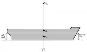
- Draft: Depth of the underwater part of a ship. There is forward draft, aft draft and mean draft. It is expressed in metres or centimetres. Symbol: d
- Deadweight: The mass that a ship can carry. This mass represents the cargo, fuel, water and everything required for proper operation of the ship. Specifically, cargo deadweight represents the mass of the cargo that can be loaded.
- Lightship displacement: Mass of a ship in light condition.
- Loaded displacement: Mass of a fully loaded ship ready for sea. Loaded displacement equals lightship displacement plus deadweight.
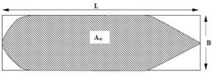
- Waterplane area: Area at the intersection of the surface of the water and the waterline of a ship. It can vary according to the ship's draft. Symbol: Aw.
- Amidships: Amidships is the midship section of a ship taken at its widest breadth. This is the reference for transverse stability calculations. It also allows you to visualize the transverse structural members of the hull.
Lightship weight
Real weight of an empty ship
Deadweight is the total mass of goods that a ship can carry at its maximum permissible draft (including fuel, fresh water, gear, provisions, etc.)
Loaded displacement
Lightship + deadweight = loaded displacement
3.2.2. Archimedes' principle
Any body immersed in a liquid is subject to an upward vertical force equal to the weight of the displaced mass of water.
Experiment 1
Situation 1
Vessels 1 and 2 are identical and empty.
The weight W is in the air.
The scale is balanced with the weights placed in the right pan.
The tank is filled to the rim with liquid.
Situation 2
The weight is immersed.
The liquid that spilled from the tank is in vessel 2.
The scale is unbalanced.
The weight thus appears to be buoyed up by vertical thrust.
Situation 3
The weight is still immersed.
Vessels 1 and 2 have been interchanged. The balance has been re-established.
Therefore, the buoyancy that caused the unbalance was equal to the weight of the volume of water displaced.
Conclusion
If we generalize, we can say that any solid object immersed in a fluid (liquid or gas) is subject to an upward vertical buoyant force equal to the weight of the volume of fluid displaced. This is called Archimedes' principle, which he came up with around 250 BC. Legend has it that he was taking a bath at the time of his discovery and ran into the street shouting EUREKA.
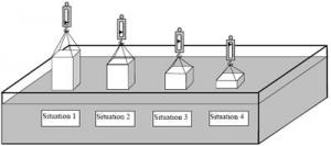
Archimedes' discovery allows us to understand why a boat floats, even if it sometimes weighs an enormous amount. Let's look at what happens when we gradually immerse a vat carrying a total weight of 100 kN in a tank.
Experiment 2
Situation 1
The 100 kN vat is suspended over the water.
The dynamometer shows that F = 100 kN to hold it in this position.
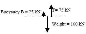
Situation 2
The vat is partially immersed in the tank.
The weight is still 100 kN.
The dynamometer shows that F = 75 kN.
Buoyancy B from the water is 25 kN.
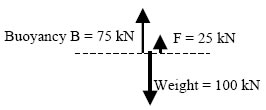
Situation 3
The vat is immersed deeper in the tank.
The weight is still 100 kN.
The dynamometer shows that F = 25 kN.
Buoyancy B from the water is 75 kN.
Situation 4
The vat is floating.
The weight is still 100 kN.
The dynamometer shows that F = 0 kN.
Buoyancy from the water is 100 kN.
With respect to stability, Archimedes' principle can be expressed as: the mass of a body immersed in a fluid is equal to the mass of the volume of fluid displaced.
When a ship is floating freely at rest, the mass of the ship (displacement, Δ) is equal to the mass of the volume of water displaced by the ship.
Δ = ∇ × ρ
kg = m3 × kg/ m3
OR
Δ = ∇ × specific gravity
t = m3 × t/ m3
3.2.2.a. Solved problems
3.2.2.a.(i) Example 1
A block of wood measuring 1 m × 1 m × 1 m is floating in fresh water (density = 1,000 kg/ m3) with a draft of 0.5 m. What is the mass of the block of wood?
- Find the underwater volume of the wood:
Underwater volume = 1 m × 1 m × 0.5 m = 0.5 m3 of immersed wood - Find the volume of water displaced:
The underwater volume of the wood is equal to the volume of water displaced = 0.5 m3. - Find the mass of the volume of water displaced:
Volume of water displaced = 0.5 m3; if 1 m3 of pure water has a mass of 1,000 kg, then a volume of 0.5 m3 has a mass of 500 kg.
The mass of the volume of water displaced is 500 kg. - Find the mass of the block of wood:
The mass of the floating object = mass of water displaced = 500 kg = 0.5 tonne.
Δ = ∇ × ρ
Δ = 0.5 m3 × 1,000 kg/ m3 = 500 kg
3.2.2.a.(ii) Example 2
A rectangular barge is floating in salt water (ρ = 1,025 kg/ m3) and has a draft of 2.5 m. The length and breadth of the barge are 75 m and 20 m, respectively. Find the barge's displacement.
- Find the underwater volume of the barge:
Underwater volume = 75 m × 20 m × 2.5 m = 3,750 m3 - Find the volume of water displaced:
The volume of water displaced is equal to the underwater volume of the barge = 3,750 m3 - Find the mass of the volume of water displaced:
3,750 m3 of salt water (1 m3 of salt water has a mass of 1,025 kg)
3,750 m3 × 1,025 kg/ m3 = 3,843,750 kg = 3,843.75 tonnes - Find the mass of the barge:
The mass of the floating object = mass of water displaced = 3,843.75 tonnes
Δ = ∇ × ρ
Δ = 3,750 m3 × 1,025 kg/ m3 = 3,843.75 tonnes
3.2.2.a.(iii) Problem 3
A barrel is 1 m in diameter and 1.5 m in height. Its mass when empty is 15 kg. It is filled with oil with a specific gravity of 0.864. What is the immersed height of the barrel when it is floating upright in water with a specific gravity of 1.015?
- Find the total volume of the barrel.
Volume of the barrel = (π×12) ÷ 4 × 1.5 = 1.178 m3 - Find the volume and mass of the oil in the barrel:
Volume of oil = volume of the barrel = 1.178 m3
If the oil has a mass of 864 kg for 1 m3, then for a volume of 1.178 m3
1.178 m3 × 864 kg/ m3 = 1,017.8 kg = 1.0178 tonne - Find the total mass of the barrel:
Total mass of the barrel = mass of the empty barrel + mass of the oil = 15 + 1,017.8 = 1,032.8 kg = 1.0328 tonne - The volume of water displaced = underwater volume of the barrel = 1.0175 m3
- The barrel floats upright and displaces 1.0175 m3 of water, therefore the underwater volume of the barrel is 1.0175 m3.
- Find the immersed height of the barrel:
Underwater volume = (π× D2) ÷ 4 × height immersed
1.0175 m3 = (π×12) ÷ 4 × immersed height
Immersed height = 1.295 m
3.2.2.a.(iv) Problem 4
What is the weight (in Newtons) of a cast iron cube (ρ = 6,700 kg/ m3) measuring 80 cm along each edge when it is completely immersed in water with a specific gravity of 1.010?
- Find the volume and mass of the cube:
Volume = 0.8 m × 0.8 m × 0.8 m = 0.512 m3
Mass = Volume of the block × ρ of the cast iron
0.512 m3 × 6,700 kg/ m3 = 3,430.4 kg = 3.43 tonnes
The block of cast iron therefore has a mass of 3.43 tonnes - Find the mass of the water displaced by the block of cast iron:
Volume of water displaced = 0.512 m3
Mass of water displaced = 0.512 m3 × 1,010 kg/ m3 = 517.12 kg
This mass of water displaced creates upward buoyancy on the block of cast iron equivalent to 517.12 kg (according to Archimedes' law) - The cast iron cube has an equivalent mass of 3,430 kg – 517.12 kg = 2,912.88 kg
- The weight of the block of cast iron is found using F = m × a
F (Newton) = 2,912.88 kg × 9.81 m/s2 = 28,575.3 Newtons = 28.575 kN
3.2.3. Coefficients of form
3.2.3.a. Coefficient of fineness
Coefficient of fineness of the waterplane area (Cw): This coefficient (variable according to the ship's draft) can be expressed as the ratio of the waterplane area to the area of a rectangle having the same length and breadth.
Waterplane area (AW) = L × B × Cw
Cw = mean value of 0.6 to 0.8
Coefficient of fineness =
Cw = Waterplane area (AW) ÷ (L × B)
Coefficient of fineness of the waterplane area
3.2.3.b. Block coefficient
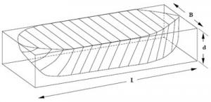
Block coefficient (Cb): Coefficient (variable according to the ship's draft) that represents the ratio of the underwater volume of a ship to a rectangular block having the same length, breadth and depth.
Block coefficient =
Cb = ∇ ÷ (L× B× d)
Mean of Cb = 0.75
Fast ships = 0.50
Slow ships = 0.80
Block coefficient
3.2.3.c. Solved problems
3.2.3.c.(i) Example 1
Find the waterplane area of a rectangular barge with a length of 50 m and breadth of 18 m.
Aw = 50 m × 18 m = 900 m2
Therefore, Cw = 900 m2 ÷ (50 m × 18 m) = 1
3.2.3.c.(ii) Example 2
A ship has a length of 100 m and breadth of 20 m. The coefficient of fineness of the waterplane area (Cw) is 0.85. Find the ship's waterplane area.
Cw = Waterplane area ÷ (L× B) = Waterplane area ÷ (100 m × 20 m) = 0.85
Waterplane area = 0.85 × 100 m × 20 m = 1,700 m2
3.2.3.c.(iii) Example 3
A ship with a length of 200 m and breadth of 22 m has a draft of 8 m. If the ship's block coefficient at this draft is 0.75, find the underwater volume of the hull (∇).
Cb = ∇ ÷ (L × B × d) = 0.75 = ∇ ÷ (200 × 22 × 8)
∇ = 0.75 × (200 × 22 × 8) = 26,400 m3
3.2.3.c.(iv) Example 4
What is the block coefficient (Cb) of a hull having a length of 150 m, breadth of 20 m and a displacement volume of 16,170 m3 at a draft of 7 m?
Cb = 16,170 m3 ÷ (150 m×20 m×7 m) = 0.77
3.2.4. Tonnes per centimetre
Tonnes per centimetre (TPC): This is the mass required to increase or decrease a ship's mean draft by 1 cm. This value varies only according to the waterplane area (Aw), and the waterplane area can vary according to the ship's draft. Therefore, the TPC can vary according to the ship's draft.
TPC = Tonnes per centimetre immersion
TPI = Tonnes per inch immersion
3.2.4.a. Solved problems
3.2.4.a.(i) Example 1
A rectangular barge having a length of 20 m and breadth of 12 m is floating in salt water (ρ = 1,025 kg/ m3).
- What is its waterplane area?
- What is its TPC?
- Find the waterplane area:
Aw = (length × breadth) at the waterline = 20 m × 12 m = 240 m2 - Find the TPC:
TPC = (Aw× ρ) ÷ 100 = (240 m2 × 1.025) ÷ 100 = 2.46 tonnes
This means that loading 2.46 tonnes on the ship will increase the draft by 1 cm. You can also say that unloading 2.46 tonnes from the ship will decrease the draft by 1 cm.
3.2.5. Effects on a ship's draft of changes in the specific gravity of water
If the specific gravity of the water in which the ship is floating changes without any changes to the ship's displacement, the ship's draft will change. The draft will change because the ship must displace the same mass of water, which no longer has the same density.
Δ = ∇ × ρ
If the displacement (Δ) remains constant and the density (ρ) changes, the underwater volume (∇) must change; therefore, the ship's draft will change automatically.
If a ship goes from fresh water to salt water, buoyancy will increase and the draft will decrease. Inversely, a ship that goes from salt water to fresh water will see its draft increase.
A ship that loads to its marks (summer load lines S) in salt water, will see its draft increase as it goes into fresh water and will exceed its marks. This situation is accepted because the absence of heavy weather on bodies of fresh water compensates for the ship's increased draft. This situation has even been made official by adding an additional mark (F) to the load lines.
3.2.5.a. Fresh Water Allowance
FWA: Inversely, a ship that loads in fresh water can load up to its " F" line, so that when it is in salt water it will float at its regular marks.
This allowed increase in draft is called the "Fresh Water Allowance".
The FWA is therefore the change in draft when a ship goes from salt water to fresh water.
Fresh Water Allowance
3.2.6. Problems to solve
3.2.6.a. Problem 1
A cube of wood with a specific gravity of 0.82 has sides of 35 cm. If a 3 kg mass is placed on the block of wood, what is its draft in salt water (specific gravity = 1.025)?
Answer: 28 cm
3.2.6.b. Problem 2
A rectangular barge with a length of 18 m, breadth of 5 m and height of 2.25 m is floating with a draft of 1.5 m in water with a density of 1,013 kg/ m3. Find the vessel’s displacement in tonnes.
Answer: 136.75 tonnes
3.2.6.c. Problem 3
An empty barrel 1 m long and 50 cm in diameter has a mass of 20 kg. What mass should be placed in the barrel so that it floats in fresh water with half of its volume immersed?
Answer: 78.17 kg
3.2.6.d. Problem 4
A rectangular wood beam 3 m long, 40 cm wide and 30 cm high is floating in fresh water with a draft of 20 cm. Find the beam's mass and density.
Answer: 240 kg; 666.6 kg/ m3
3.2.6.e. Problem 5
A ship has a length of 130 m and breadth of 21 m, with a coefficient of fineness of the waterplane area (Cw) of 0.85. Find the TPC in salt water at this draft.
Answer: 23.78 tonnes
3.2.6.f. Problem 6
A ship with a length of 65 m and a breadth of 10 m is floating with a draft of 4.5 m in salt water. The ship has a block coefficient of fineness of displacement (Cb) of 0.75. Find the ship's displacement at this draft.
Answer: 2,248.6 tonnes
3.3. Transverse statical stability
Transverse statical stability is the ship's stability at small angles of inclination. The rules of statical stability are considered to apply to angles of inclination less than 15°.
To be able to calculate stability, first the fixed and mobile points on a ship's cross section must be identified.
3.3.1. Reference point (K)
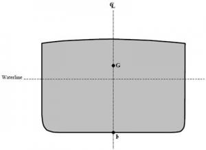
Reference point K is applied to the ship's lowest point, which is the keel. This is a fixed point.
3.3.2. Centre of gravity (G)
Transverse centre of gravity G
Before applying this concept to a ship, a few short definitions of a general nature are necessary.
The centre of gravity of a body can be defined as:
- The point at which the force of gravity is exerted vertically downwards;
- The point where a pivot can be placed that will keep the body balanced;
- The geometric centre of a uniform body.
For a ship, the centre of gravity is the point at which the force generated by the ship's mass is exerted vertically downwards. The position of the centre of gravity changes according to the ship's loading conditions.
3.3.2.a. Effects of changing load
Effects of changing load: The height of the centre of gravity depends on the vertical distribution of the ship's mobile masses such as cargo, fuel and ballast). The height of the centre of gravity is measured from reference point K. The height of the centre of gravity is identified as a ship's KG.
For a ship to float without an angle of list, point G must be on the same vertical axis as K. As soon as G leaves this vertical axis, an angle of list is produced and the ship will no longer float upright.
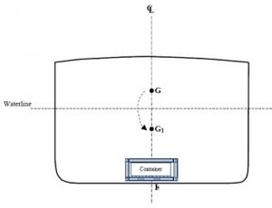
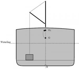
The centre of gravity can thus be shifted vertically and horizontally by transferring, adding or removing mobile masses.
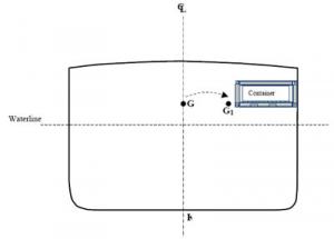
If mass is added to a ship, the centre of gravity shifts towards the position of the added mass. For example, fuel added to a ship's double bottom tanks will lower the centre of gravity. Deck cargo generally raises a ship's G. A concentration of cargo on a ship's port side will shift G to port, which will cause the ship to list to port.
Shifting of G resulting from movement of loads
The inverse is true when mobile masses are removed. For example, fuel consumption reduces the mass in the storage tanks, and if they are double bottom tanks, the loss of mass shifts G upwards. If deck cargo is unloaded, G is shifted downwards. Unloading cargo on the starboard side will shift G to port, which will result in a list to port.
If a mass already on board is moved, the position of the ship's centre of gravity will shift in the same direction as the mass. For example, shifting port ballast to starboard will shift G to starboard, which will tend to cause a list to starboard.
3.3.3. Centre of buoyancy (B)
Transverse centre of buoyancy B
A ship's centre of buoyancy can be defined as the point through which the force of buoyancy acts vertically upwards. You can also say that the centre of buoyancy is the geometric centre of the ship's underwater volume. The height of the centre of buoyancy is measured from reference point K and is thus KB.
Position of point B
3.3.4. Ship's inclination
If a ship is floating upright, its symmetrical construction will place point B on the same axis as K and G. The only way to shift the transverse centre of buoyancy is to change the ship's inclination. The underwater volume will be a different shape and B will shift to reach the new geometric centre of this underwater volume. Since the position of B depends solely on the geometry of the cross section, if the hull shape is known, it is easy to identify B based on the load and list conditions.
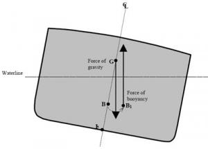
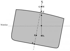
If a ship is floating upright, points K, G and B will all be on the same vertical axis. If the ship is inclined by external forces (wind, waves, tight mooring at the wharf), G should not change position (no mass has shifted), but B will shift to the geometric centre of the new underwater volume. Points B and G will no longer be on the same vertical axis, consequently the ship's weight will act vertically downwards through G and the force of buoyancy will push upwards from B1.
3.3.4.a. Righting moment
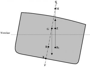
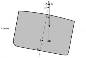
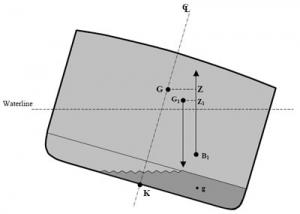
When a ship is inclined, these two forces are no longer on the same vertical axis and a righting moment is created. The righting moment tends to bring the ship back to an upright position. This moment is equal to a force multiplied by a distance. The value of the force is the same for the upwards and downwards vectors, and is equal to the ship's displacement.
Forces of gravity and buoyancy
3.3.4.b. Righting lever (GZ)
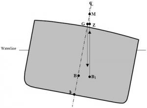
The distance between the two vectors is called GZ and represents the righting lever. The larger the righting lever, the higher the righting moment. The size of the righting lever increases with the ship's inclination. In other words, up to a certain angle of inclination (usually between 40° and 60°), the more the ship lists, the greater its tendency to return to an upright position. If the maximum righting angle is exceeded, the righting lever decreases and the ship's ability to right itself also decreases until it reaches an angle where the righting lever is zero and the ship is in serious danger of capsizing.
Inversely, if G is located high on the centreline, the righting lever will be smaller so the righting moment will be weaker. The ship will right itself more slowly.
The value of the righting moment (also called the moment of statical stability, MSS) is calculated by the formula
MSS = Δ × GZ
To find the value of GZ at small angles of inclination, the following trigonometric equation is used:
GZ = GMsin Θ.
Θ being the ship's angle of inclination.
Righting moment
3.3.5. Metacentre (M)
Looking at the inclination diagram, you can see that a point M has appeared. Point M is located at the intersection of the buoyancy vector and the centreline and is called the metacentre. For small angles of inclination (less than 15°), M is considered to be fixed. The presence of M allows us to introduce a new concept that actually controls stability at small angles of inclination.
3.3.6. Metacentric height (GM)
This is the distance between G and M, which is identified as distance GM, also called the metacentric height.
Righting moment with a reduced GM
The position of G in relation to M is crucial in a ship's ability to right itself. Under normal conditions, G should always be below M. The GM is then said to be positive. The greater the distance between these two points, the higher the positive GM. As stated in the previous paragraph, the larger the GM, the larger the righting lever. If G approaches M, the righting lever decreases and the righting moment is weak.
If GM is zero, meaning that G coincides with M, the righting lever is non-existent. If an external force then makes the ship heel to a small angle, the ship will remain heeled at this angle because there is no righting moment.
If GM is negative, meaning that G is above M, not only is the righting lever non-existent, but it also becomes a capsizing moment. If the ship is then subjected to a light external force, it will incline sharply and, depending on the shape of the hull, may even capsize completely. In any case, a negative GM is a situation that must absolutely be avoided.
Neutral equilibrium when GM = 0
Capsizing moment with a negative GM
3.3.7. Abrupt shifting of G
Two situations have a radical effect on the position of G. In both situations, an abrupt rise in G occurs, which in some extreme cases can lead to a situation where GM becomes negative. Both situations are a result of the free surface effect and the effect of suspended weight.
3.3.7.a. Suspended weight
When cargo is handled using cranes or cargo booms mounted on a ship, the centre of gravity of the mass being handled is considered to be at the point of suspension, which is the end of the crane arm or cargo boom. For example, if a crane lifts a mass of 5 tonnes from the bottom of a hold, as soon as the mass leaves the surface it was resting on, the centre of gravity of these 5 tonnes is instantly transferred from the bottom of the hold to the head of the crane arm. This causes an instant and sometimes significant rise in the ship's G. If the GM was already small, this change in position can result in a negative GM.
Effect of a suspended weight
3.3.7.b. Free surface effect
The other situation is the occurrence of the free surface effect. If a ship's tank is partially filled and the ship rolls, the mass of liquid in the tank moves uncontrollably. The centre of gravity of the liquid mass shifts from side to side, and the change in "shape" of the liquid can also cause the G of the moving mass to rise radically. In addition, the inertia of the liquid mass moving around affects the ship's transverse stability and the position of its G. The effect of the inertia of the moving liquid is applied by making a virtual change to the position of G. This change in the height of G of the liquid mass can have a radical effect on the ship's height of G, which can result in a negative GM. To reduce the free surface effect, anti-rolling devices are placed in the tanks.
Free surface effect
A combination of these two situations can occur when a ship is loading or unloading. Cargo handling is often combined with ballast handling. While in port, fuel or storage transfers can be done. Free surfaces can appear in ballast as well as fuel tanks. When this situation occurs during cargo handling with cranes or cargo booms, a negative GM can easily be created.
As an engineer, in some situations during a layover in port, you must check with the officer in charge of the ship's stability before transferring liquid masses.
All the values for the above terms for a ship can be found in the ship's stability book.
All the concepts covered in this chapter make it possible to maintain a ship's intact stability.
A ship's intact stability is defined as the stability of an undamaged ship that meets IMO requirements as set out in the Code on Intact Stability for all Types of Ships Covered by IMO Instruments.
3.4. Simple longitudinal stability
The principles of transverse stability apply partly to create longitudinal stability.
Points K, G, B and M from transverse stability are used with a ship's longitudinal section. They become points GL, BL and ML.
The longitudinal metacentre (ML) is found the same way as for transverse stability. It will be located at the intersection of the vertical lines passing through points BL and BL1 when the trim is adjusted.
Longitudinal stability
In longitudinal stability, trim can be considered as the equivalent of list in transverse stability. Trim represents the longitudinal inclination of the ship and instead of being expressed in degrees, it is given as a difference between the forward and aft drafts.
When aft draft is greater than forward draft (usual situation), the trim is positive. When forward draft is greater, the trim is negative.
For example: a ship with a forward draft of 5 m and an aft draft of 5.75 m will have a positive trim of 75 cm.
Shifting, loading and unloading of a mass will affect a ship's trim. The change in trim when handling masses is measured using the concept of MCTC and MCTI.
MCTC is the Moment to Change Trim 1 centimetre.
MCTI is the Moment to Change Trim 1 inch.
All the values for the above terms for a ship can be found in the ship's stability book.
4. Construction
4.1. Definitions of hull elements
- Keel: The keel is a member, or series of members, running longitudinally that forms the structural base of a ship. The keel always corresponds to a ship's centreline. It is a major component in providing longitudinal strength and efficiently distributes local stresses when the ship is dry docked. There are two types of keels used to build ships of a certain size, the flat keel and the duct keel.
Flat keel
Duct keel
- Girders: A girder is a longitudinal member used in the construction of the bottom of a ship. They can be solid or not and can be placed above the keel (centre girder) or spaced equal distances from it (side girders). They can be continuous or divided by floor sections (intercostal side girders). The centre girder is always one continuous piece and must be fastened to the keel with a continuous weld. Girders must extend as far as possible from the forward to the aft end of a ship.
- Floors: These are made up of cross members that are mounted perpendicular to the keel and girders. There are three main types of floor: solid, plate and bracket.
Plate floor
Solid floor
Bracket or open floor
- Frames: These are vertical members that make up the framing of the vertical part of the hull. Frame type and spacing vary considerably depending on the ship's construction.
Shell framing
- Deck beams: These are transverse members that connect the top ends of the frames, forming the transverse framing for the deck.
Longitudinal framing, deck and shell
- Deck girders: These are longitudinal members that combine with the beams to form the longitudinal framing of the deck.
- Longitudinals: A very general term to identify any small longitudinal member that can be used for several purposes. This term is used more specifically in longitudinal framing.
- Web frames: Oversized members that replace a frame at certain locations on a ship.
- Bracket: A general term that identifies any part used to connect two members.
- Beam knee: Bracket located at the end of deck beams that connect the beam and frame to the shell plating.
- Pillar: Vertical member inside a ship that connects the deck to the ship's bottom, where it is installed between two tweendecks, especially around hatches. They are quite bulky and complicate cargo handling inside holds.
- Plating: The plating of a hull is the series of plates that form the watertight shell of the hull. There is bottom plating, deck plating and side shell plating.
- Bilge plating: Longitudinal plating that connects the side shell plating to the bottom plating.
- Tank top: Watertight series of plates attached to a ship's bottom framework.
- Double bottom: The double bottom is the watertight space between the bottom plating and the tank top. Its height varies according to the size and type of ship, but it is generally between 0.75 and 1.5 metres. A double bottom is divided into several watertight compartments by watertight floors and girders. These compartments can be used to store fuel, oil and ballast water. They are often used to adjust a ship's list and trim.
A double bottom maintains a ship's watertight integrity when the bottom is damaged. The tank top greatly increases a ship's longitudinal strength and forms a platform to carry the ship's cargo and machinery.
Transversely framed double bottom
Longitudinally framed double bottom
4.2. Types of construction
4.2.1. Transverse framing
Transverse framing is used primarily for ships less than 120 metres in length. The floors, frames and beams form rings spaced closely together. Longitudinal strength is provided by the keel, centre girder, side girders, deck girders, the entire bottom, deck and side shell plating, and the tank top. Transverse framing ensures good cross sectional strength to handle overall stresses, vertical loads, rolling and dry docking. However, on very long ships, sheer stresses can cause deformations between the rings.
4.2.2. Longitudinal framing
Longitudinal framing is mandatory for very large ships, oil tankers and bulk-ore carriers. The rings are formed of floors, deck beams and web frames that replace the frames. These rings are farther apart than in transverse framing. The longitudinal reinforcement members are deck girders, girders, the keel and a large number of deck, bottom and side longitudinals. The longitudinals are slender but there are very many of them.
4.2.3. Mixed framing
Mixed framing combines longitudinal and transverse framing. One type of framing is used in one part of the ship and the other type is used in another part. The most common combination is longitudinal framing for the bottoms and the deck, and transverse framing for the sides.
4.3. Stresses and constraints on ship structure
4.3.1. Static stresses and constraints
These stresses are measured when the ship is not under way. They are often caused by a poor longitudinal distribution of mass. Even if the ship's total weight is balanced by the total force of buoyancy, these forces may not be distributed evenly along the full length of the ship.
- Hogging: If the forces of buoyancy are concentrated around the section amidships and the ends are loaded, the ship will tend to move downwards at the bow and stern while the section amidships will tend to move upwards. In this situation, the deck's structural members are being subjected to tensile stress while the bottom structure is under compressive stress. This phenomenon can be compared to a beam supported in the centre and loaded with weights on the ends.
Hogging
- Sagging: If the forces of buoyancy are concentrated under the bow and stern of the ship and the section amidships is loaded, the ship will tend to move upwards at the ends and trough amidships. In this situation, the deck's structural members are under compressive stress while the bottom structure is being subjected to tensile stress. This phenomenon can be compared to a beam that is supported at both ends and loaded with weights in the middle.
Hogging and sagging can be amplified by the movement of waves passing along the hull. A crest of waves at each end of a ship combined with a trough amidships will amplify sagging, while a crest amidships combined with a trough at both ends will amplify hogging.
The stresses caused by these situations can be calculated using the load curves table, the stress and sheer curves table, and the bending moments table. Manual or electronic calculators also exist to find the value of the stresses on the hull. The maximum permissible stress values can be found in the ship's stability book.
4.3.2. Dynamic stresses and constraints
When a ship is under way, some situations create additional stresses. They are caused primarily by the effect of waves on the hull in rough seas. Two of these are pounding and panting.
- Pounding: When a ship sails in heavy seas, it pitches. It can happen that the bow rises over the crest of a wave and emerges completely out of the water. When the bow comes back down on the water, it can be subjected to a major impact, which is pounding. The hull plating at the bow end of the ship must be reinforced to avoid bending of the plating. This stress can also occur at the ship's stern, but to a lesser degree.
- Panting: When waves hit the bow and stern of a ship, they create variations in pressure that tend to push the plating in and out. This is panting. The framing at the ship's ends must be reinforced to prevent exaggerated movement of the hull plating.
4.4. Watertight bulkheads
A watertight bulkhead is a transverse bulkhead mounted on the tank top and it must extend right to the uppermost continuous deck.
Watertight bulkheads are installed to:
- Divide the ship into watertight compartments and thereby limit flooding if the hull plating is damaged;
- Improve the transverse strength of the structure;
- Prevent distortion of the hull plating;
- Support the deck girders and longitudinals;
- Rigidly attach the tank top to the upper deck;
- Greatly slow the spread of fire.
The number and location of watertight bulkheads on a ship depend on the length and type of ship and the location of the machinery space. The SOLAS Convention determines the number and location of these bulkheads. But in general, there is a watertight bulkhead (collision bulkhead) at the bow that should be located between 0.05 L and 0.075 L (L = length between perpendiculars of a ship), a watertight bulkhead at the stern that should form a watertight aft compartment (after peak) that encloses the stern tube, and a watertight bulkhead at each end of the machinery space (where the aft bulkhead may be the after-peak bulkhead).
All members that pass through a watertight bulkhead, such as ventilation ducts, piping and electric wiring, must be mounted so as to maintain the watertight integrity of the bulkhead. That is why remote controlled stopcocks are generally found on certain pipes that pass through watertight bulkheads.
4.5. Watertight doors
In some situations, it is necessary to pierce bulkheads to allow crew or passengers through. In this case, a sliding watertight door is installed. An example of this situation is the watertight door that is found on some ships between the machinery space and the shaft tunnel. Liners have many of these doors that allow passengers to go between the different sections of the ship. These watertight doors are usually hydraulically activated. Local control stations must be located on either side of the door. In addition, a remote control station (generally located in the wheelhouse) must be placed outside both compartments separated by the watertight bulkhead.
Chapter II-1, Regulation 15 of the SOLAS Convention governs the installation and operating requirements for these doors.
Extract, Regulation 15,
7.1.6: [A watertight door] shall be provided with an audible alarm, distinct from any other alarm in the area, which will sound whenever the door is closed remotely by power and which shall sound for at least 5 s but no more than 10 s before the door begins to move and shall continue sounding until the door is completely closed. In the case of remote hand operation it is sufficient for the audible alarm to sound only when the door is moving. Additionally, in passenger areas and areas of high ambient noise the Administration may require the audible alarm to be supplemented by an intermittent visual signal at the door; and
7.1.7: shall have an approximately uniform rate of closure under power. The closure time, from the time the door begins to move to the time it reaches the completely closed position, shall in no case be less than 20 s or more than 40 s with the ship in the upright position.
Watertight bulkhead
Watertight door operating mechanism
5. Machinery installation
As mentioned above, Chapter II-1, "Construction - Structure, subdivision and stability, machinery and electrical installations" of the SOLAS Convention defines the specific regulations for ship construction related to the hull and installation of machinery.
Below we will take a look at some elements related to the machinery installation.
5.1. Steering gear
Requirements for steering gear
The Convention states that all ships must be equipped with steering gear and that tests done on this gear must meet specific criteria.
The requirements are very specific and precise. For example, when a ship is at its deepest draft and running ahead at maximum ahead service speed, the main steering gear shall be able to turn from 35 degrees on one side to 30 degrees on the other side in no more than 28 seconds. As for the auxiliary steering gear, it shall be able to go from 15 degrees on one side to 15 degrees on the other side in the same conditions as the main steering gear in not more than 60 seconds.
5.2. Emergency generating sets
Requirements for emergency generating sets
Requirements for emergency generating sets involve starting in cold condition and starting energy-storing devices.
The Convention contains the following in the regulations:
- Emergency generating sets shall be capable of being readily started at a temperature of 0° C. If this is impracticable, or if lower temperatures are likely to be encountered, provision shall be made for the maintenance of heating arrangements.
- Each emergency generating set arranged to be automatically started shall be equipped with starting devices approved by the Administration with a stored energy capability of at least three consecutive starts. A second source of energy shall be provided for an additional three starts within 30 min unless manual starting can be demonstrated to be effective.
- Ships constructed on or after 1 October 1994, in lieu of the provision of the second paragraph of the section above, shall comply with the following requirements:
- The source of stored energy shall be protected to preclude critical depletion by the automatic starting system, unless a second independent means of starting is provided. In addition, a second source of energy shall be provided for an additional three starts within 30 min unless manual starting can be demonstrated to be effective.
- The stored energy shall be maintained at all times, as follows:
- electrical and hydraulic starting systems shall be maintained from the emergency switchboard;
- compressed air starting systems may be maintained by the main or auxiliary compressed air receivers through a suitable non-return valve or by an emergency air compressor which, if electrically driven, is supplied from the emergency switchboard;
- all of these starting, charging and energy-storing devices shall be located in the emergency generator space; […]. This does not preclude the supply to the air receiver of the emergency generating set from the main or auxiliary compressed air system through the non-return valve fitted in the emergency generator space.
- Where automatic starting is not required, manual starting is permissible, such as manual cranking, inertia starters, manually charged hydraulic accumulators, or powder charge cartridges, where they can be demonstrated as being effective.
- When manual starting is not practicable, the requirements of paragraphs 2 and 3 shall be complied with except that starting may be manually initiated.
The section on electrical installations sets out all the requirements concerning a ship's power supply. Clearly, Regulation 44 provides requirements for the starting systems of emergency generating sets.
5.3. Fire mains
Pressure requirements for fire mains
The fire-fighting system is also a central element of the SOLAS Convention, so it contains many requirements.
Chapter II-2, Regulation 4 of the SOLAS Convention, "Fire pumps, fire mains, hydrants and hoses" contains the details of the regulations governing this aspect.
The maximum pressure calculation must be done with standard nozzle sizes. The fire hose nozzle specifications are set out in point 8: Nozzles. It states that for machinery spaces and exposed locations, the nozzle size shall be such as to obtain the maximum discharge possible from two jets at the pressure mentioned in paragraph 4 from the smallest pump, provided that a nozzle size greater than 19 mm need not be used.
All nozzles shall be of an approved dual-purpose type (i.e., spray/jet type) incorporating a shutoff.
The maximum pressure is the pressure that the system can support. This means that it shall not exceed that at which the effective control of a fire hose can be demonstrated.
The minimum pressure required varies based on the type of ship (passenger ship or cargo ship) and its tonnage according to the table below:
Passenger Ships
Cargo Ships
5.4. Propellers
A ship's propeller is the last piece of equipment in the propulsion system. Propeller efficiency depends on many factors, the main ones being:
- Propeller and hub diameters
The difference between the two is the effective surface. In general, a greater effective surface means higher efficiency. - Propeller rotation speed
Generally, slower propeller rotation speed means better efficiency. - Number of blades
In theory, fewer blades mean greater efficiency (3 or 4 blades). However, a higher number of blades (up to 8) greatly reduces vibration, which can be useful on passenger ships and naval ships. - Blade angle
This is the most difficult criteria to evaluate when designing a propeller. This angle depends on all the factors listed above. In addition, it is preferable for the angle to change on a blade. For instance, the blade angle is more pronounced close to the hub and less pronounced near the blade tip. - Propeller pitch
Propeller pitch is defined as the linear distance covered by the propeller in one complete revolution, if the propeller were operating in a solid. The actual linear distance covered will be less because water is not a solid. - Propeller slip
If propeller blades could operate in a solid, travel per rotation would be equal to the pitch. But since water is not solid, the propeller action is weaker and the thruster "slips" in the substance in which it is operating. Actual travel per rotation is thus less than the pitch. Slip is expressed as a percentage.
Slip = (Pitch − Actual traven per rotation) ÷ Pitch
6. Bibliography
6.1. Bibliography
The following acts are available at this Web site: http://laws-lois.justice.gc.ca/eng/
- Pilotage Act
- Marine Transportation Security Act
- Navigable Waters Protection Act
- Canada Shipping Act
For more information on the process by which Canadian acts and regulations are adopted, see the following Web sites:
http://dsp-psd.pwgsc.gc.ca/Reference/queens-e.html
http://www.pco-bcp.gc.ca/raoics-srdc/
All the regulations below are available at this address:
https://apps.tc.canada.ca/en/corporate/acts-regulations
- Oil Pollution Prevention Regulations
- Air Pollution Regulations
- Pollutant Substances Regulations
- Pollutant Discharge Reporting Regulations
- Life Saving Equipment Regulations
For additional information on the regulations regarding environmental protection, visit:
https://apps.tc.canada.ca/en/marine-transportation/marine-safety/environmental-protection
More information on International Maritime Organization (IMO) publications is available at: http://www.imo.org/index.htm
International Conventions
- MARPOL 73/78 Consolidated Edition, 1997. International Maritime Organization, London, 1997, 419 p.
ISBN: 92-801-1435-2 - SOLAS CONVENTION 1974. Consolidated Edition 2001. International Maritime Organization, London, 2001, 577 p.
ISBN: 82-801-2278-9 - IMDG Code. International Maritime Dangerous Goods Code, 2002 Edition. International Maritime Organization, London, 2002, 438 p.
ISBN: 92-801-5140-1
DERRETT, D.R. Ship Stability For Masters and Mates, London, The Maritime Press Limited, 1973, 395 p.
BRUNO, André, and Claude MOUILLERON-BÉCAR. Dictionnaire maritime thématique anglais et français, Paris, Masson, 1994, 442 p.
OTTAWA, Canadian Coast Guard. An Introduction to Fishing Vessel Stability, 29 p.


