Table of contents
- 1 Interpretation
- 2 Introduction
- 3 Damage stability
- 3.1 Standard of subdivision – all vessels
- 3.2 Standard for subdivision of passenger vessels of more than 40 metres in length operating in the sea ice areas of Eastern Canada
- 3.3 Damage stability criteria for all passenger vessels
- 3.4 Damage stability criteria for vessels constructed on or after October 1, 2007
- 3.5 Damage stability criteria for vessels constructed before October 1, 2007
- 3.6 Additional damage stability criteria for passenger vessels of more than 40 metres in length operating in the sea ice areas of Eastern Canada
- 3.7 Principles for calculating maximum heeling moments
Notice
To ensure compliance, it is the responsibility of the reader to consult the Vessel Construction and Equipment Regulations.
1 Interpretation
B means the greatest moulded breadth at or below a vessel’s deepest subdivision load water line.
bulkhead deck has the same meaning as in SOLAS Chapter II-1, regulation 2.19.
deepest subdivision load waterline means the waterline that corresponds to the deepest draught.
length or L has the same meaning as in the Vessel Construction and Equipment Regulations.
main compartment means any compartment between two main transverse watertight bulkheads.
margin line means a line drawn at least 76 mm below the upper surface of the bulkhead deck at the side of a vessel.
persons in relation to the number of persons carried means the total complement on board the vessel (passengers and crew).
upper ice waterline means the waterline defined by the maximum draughts forward and aft for operation in ice.
1.1.1 All words and expressions used in this Standard have the same meaning as in the Canada Shipping Act, 2001 and the Vessel Construction and Equipment Regulations (VCER).
2 Introduction
2.1 General
2.1.1 This Standard gives alternative requirements to SOLAS on subdivision and damage stability criteria for non-convention passenger vessels. These requirements have been adapted as an alternative to the damage stability requirement of SOLAS Chapter II-1, taking into consideration the size of vessels, their operation in protected waters, and their date of construction before the coming into force of the VCER.
2.1.2 Recognizing that special risks of ice damage may occur in certain waters off the East Coast of Canada and that these risks can endanger safety of life at sea, additional damage stability criteria for passenger vessels of more than 40 metres in length operating in the sea ice areas of eastern Canada, as illustrated in Annex 1 of TP 15415, have been adopted in this standard.
2.1.3 A vessel that complied with TP 10943 (2007) before this edition and the VCER came into force can continue to do so until the first anniversary of the coming into force, as prescribed in section 10 of the VCER. After the first anniversary, the vessel is deemed to comply until it is subject to an alteration that affects its stability as per SOLAS Chapter II-1, regulation 5.4, or when the lightship survey required by SOLAS Chapter II-1, regulation 5.5 requires the vessel to be re-inclined and its stability recalculated.
3 Damage stability
3.1 Standard of subdivision – all vessels
3.1.1 All vessels must have at least three transverse watertight bulkheads, namely one collision bulkhead and one bulkhead forward and one aft of the main engine room.
3.1.2 If the distance between two adjacent main watertight bulkheads is less than 0.03L + 3.05 m, or 11 m, or 0.1L, whichever is the least, only one of those bulkheads shall be regarded as forming part of the subdivision of the vessel.
3.1.3 All vessels that carry more than 12 passengers, but less than 400 persons, must have sufficient stability in all service conditions to withstand the final stages of flooding of any main compartment.
3.1.4 To provide the stability outlined in section 3.1.3, vessels that carry fewer than 50 persons may be fitted with a closed-cell buoyant material or subdivided into watertight compartments.
3.1.5 The use of low-density foam or other media may be permitted to provide buoyancy in void spaces, provided that satisfactory evidence is provided that any such proposed medium is the most suitable alternative and is:
- (a) Of close-cell form if foam, or otherwise impervious to water absorption.Footnote 1
- (b) Structurally stable under service conditions.
- (c) Chemically inert in relation to structural materials with which it is in contact or other substances with which the medium is likely to be in contact.
- (d) Properly secured in place and easily removable for inspection of the void spaces.
3.1.6 The void spaces where buoyant material is installed:
- (a) Must not include anything that could ignite a fire.
- (b) Must be protected from adjacent fire hazard areas by fire-resisting divisions.
- (c) Must be strong enough to accommodate the buoyancy of the material under service conditions.
- (d) Must not have piping and cables passing through the buoyant material unless they are within a piping or a cable trunk that can be reached from both ends for maintenance purposes.
3.1.7 Buoyant material’s specification, position and volume must be noted in the vessel’s stability booklet.
3.1.8 A vessel, other than a ro-ro passenger ferry, constructed on or after October 1, 2007 and certified to carry 400 persons or more must have sufficient stability in all service conditions to withstand the final stages of flooding of two adjacent main compartments.
3.1.9 A ro-ro passenger ferry certified to carry 400 persons or more must have sufficient stability in all service conditions to withstand the final stages of flooding of two adjacent main compartments.
3.1.10 A vessel, other than a ro-ro passenger ferry, constructed before October 1, 2007, must be provided with sufficient stability to withstand flooding as follows:
|
Number of persons carried |
Subdivision requirement |
|---|---|
|
< 50 unberthed; or ≤ 12 berthed |
Three transverse watertight bulkheads. |
|
≥ 50 < 400 unberthed; or > 12 < 400 berthed |
Any main compartment. |
|
≥ 400 < 600 |
Any two adjacent main compartments that are flooded within at least 40% of the vessel length forward. Any other main compartment located elsewhere. |
|
≥ 600 < 800 |
Any two adjacent main compartments that are flooded within at least 60% of the vessel length forward. Any other main compartment located elsewhere. |
|
≥ 800 |
Any two adjacent main compartments. |
3.1.11 The requirements of sections 3.1.3 to 3.1.10 must be calculated according to sections 3.3 to 3.7 of this Standard. When making these calculations, it must be assumed that the vessel is in the worst anticipated service conditions with regards to intact stability or freeboard.
3.1.12 If a lesser extent of damage will give a more severe result, such extent is to be assumed.
3.2 Standard for subdivision of passenger vessels of more than 40 metres in length operating in the sea ice areas of Eastern Canada
3.2.1 In addition to the subdivision requirements applicable to all vessels, passenger vessels of more than 40 metres in length operating in the sea ice areas of eastern Canada, as illustrated in Annex 1 of TP 15415, must have sufficient stability in all service conditions to withstand the final stages of flooding of two adjacent main compartments using the damage extent specified in 3.2.2, and the criteria specified in 3.6.
3.2.2 The ice damage extents to be assumed when demonstrating compliance with section 3.2 for passenger vessels in the sea ice areas of eastern Canada must be as follows:
|
Direction of damage |
Extent |
|---|---|
|
Longitudinal extent |
⅓ L⅔ or 14.5 metres, whichever is less, positioned so as to include at least two consecutive compartments anywhere within the length of the vessel. |
|
Transverse extent |
0.1 of the B of the vessel or 2 metres, whichever is less, measured inboard from the vessel’s side at right angles to the centre line at the level of upper ice waterline but not to be less than 1 metre inboard from the vessel’s side. |
|
Vertical extent |
From the base line upwards, without limit. |
|
If a lesser extent of damage will give a more severe result, such extent is to be assumed. |
|
3.2.3 As an alternative to the requirements of 3.2.1 and 3.2.2, passenger vessels may comply with the requirements for stability in damaged conditions as provided in section 4.3.2 of Part A of the International Code for Ships Operating in Polar Waters (Polar Code), adopted by IMO Resolution MSC.385(94), without regards to the ship category.
3.3 Damage stability criteria for all passenger vessels
3.3.1 Unsymmetrical flooding must be kept to a minimum with efficient arrangements.
3.3.2 If it is necessary to correct a large angle of heel, the method used must be self-acting, where practicable. If the vessel is fitted with controls for cross-flooding fittings, they must be operable from above the bulkhead deck. These fittings and their controls must be built and installed to a recognized standard.
3.3.3 The maximum angle of heel after flooding, but before equalization, cannot be more than 15°.
3.3.4 If cross-flooding fittings are required, they must be fitted with adequate venting to avoid over pressurization.
3.3.5 The time for equalization must not exceed 15 minutes.
3.3.6 The master of the vessel must be given information about the cross-flooding fittings in accordance with the IMO Resolution MSC.362(92), Revised Recommendation on a standard method for evaluating cross-flooding arrangements.
3.3.7 The final condition of the vessel after damage and, in the case of unsymmetrical flooding, after equalization measures have been taken must be as follows:
- (a) In the case of symmetrical flooding there must be a positive residual metacentric height of at least 0.05 metres as calculated by the constant displacement method (lost buoyancy).
- (b) In the case of unsymmetrical flooding, the equilibrium angle of heel (ӨEQ) for one-compartment flooding must not exceed 7°. For the simultaneous flooding of two or more adjacent compartments, the equilibrium angle of heel must not exceed 12°.
- (c) In no case can the margin line be submerged in the final stage of flooding.
3.3.8 In the intermediate stages of flooding, the maximum righting lever (GZ) must be at least 0.05 metres and the range of positive righting levers must be at least 7°. The added weight method, considering the actual shifting of the center of gravity of the flooded water for each percentage of flooding and angle of heel calculated, must be used for calculation of intermediate stages of flooding.
3.3.9 In the intermediate stages of flooding, taking into account sinkage, heel and trim, none of the following can occur:
- (a) Immersion of any vertical escape hatch on the bulkhead deck.
- (b) Any controls intended for operation of watertight doors, equalization devices and valves on piping or ventilation ducts intended to maintain the integrity of watertight bulkheads from above the bulkhead deck become inaccessible or inoperable.
- (c) Piping or ventilation ducts that pass through a watertight boundary in any damaged section cannot be under water unless they are fitted with a watertight closure at each boundary. Arrangements are to be made to ensure that progressive flooding cannot extend to sections other than those assumed flooded.
3.4 Damage stability criteria for vessels constructed on or after October 1, 2007
3.4.1 Vessels on near coastal voyages, Class 1, or vessels carrying 50 persons or more on near coastal voyages, Class 2
3.4.1.1 In addition to section 3.3, vessels on near coastal voyages, Class 1, or vessels carrying 50 persons or more on near coastal voyages, Class 2, must meet the following stability criteria after damage, and equalization if applicable:
-
(a) The positive residual righting lever curve must have a minimum range of 15° beyond the angle of equilibrium (ӨEQ). This range can be reduced to 10° when the area under the righting lever curve specified in (b) of this section, increases by the ratio:
15 / range
where the range is expressed in degrees.
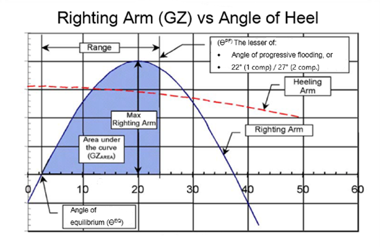
- (b) The area under the righting lever curve must be at least 0.015 metre-radians measured from the angle of equilibrium (ӨEQ) to angle of progressive flooding (ӨPF), which would be the minimum angle of the following:
- i) The angle where progressive flooding occurs.
- ii) In the case of one compartment flooding, 22° (measured from the upright).
- iii) In the case of the simultaneous flooding of two or more adjacent compartments, 27° (measured from the upright).
- (c) The maximum righting arm (lever) must be at least 0.04 metres greater than the heeling arm resulting from greatest of the heeling moments as specified and calculated according to sections 3.7.6 to 3.7.8:
- i) The crowding of all passengers to one side.
- ii) The launching of all fully loaded davit-launched survival craft on one side.
- iii) Wind pressure.
- (d) The maximum righting arm must be at least 0.10 metres.
3.4.2 Vessels on sheltered water voyages, or vessels carrying less than 50 persons on near coastal voyages, Class 2
3.4.2.1 In addition to section 3.3, vessels on sheltered water voyages, or near coastal voyages, Class 2 carrying less than 50 persons must have a maximum righting arm greater than the largest heeling arm as specified and calculated according to sections 3.7.6 to 3.7.8:
- (a) The crowding of all passengers to one side.
- (b) The launching of all fully loaded davit-launched survival craft on one side.
- (c) Wind pressure.
3.5 Damage stability criteria for vessels constructed before October 1, 2007
3.5.1 The area under the righting lever curve of vessels specified in section 3.5.2, must be measured from the angle of equilibrium to the lowest angle of the following:
- (a) The angle where progressive flooding occurs.
- (b) In the case of one compartment flooding, 22° (measured from the upright).
- (c) In the case of the simultaneous flooding of two adjacent compartments, 27° (measured from the upright).
3.5.2 In addition to section 3.3 the area under the righting lever curve for vessels carrying 50 persons or more must be greater than:
- (a) 0.015 metre-radians for vessels certified to operate on near coastal voyages, Class 1.
- (b) 0.0075 metre-radians for vessels certified to operate on near coastal voyages, Class 2.
3.5.3 In addition to meeting the requirements in section 3.3, the maximum righting arm for these vessels must be greater than the largest heeling arm calculated from the following effects. This must be calculated according to sections 3.7.6 to 3.7.8:
- (a) The crowding of all passengers to one side.
- (b) The launching of all fully loaded davit-launched survival craft on one side.
- (c) Wind pressure.
3.6 Additional damage stability criteria for passenger vessels of more than 40 metres in length operating in the sea ice areas of Eastern Canada
3.6.1 The final condition of the vessel after damage and in the case of unsymmetrical flooding after equalization measures have been taken must be as follows:
- (a) The righting lever curve (GZ) must have a minimum range of 20º beyond the position of equilibrium.
- (b) The righting lever (GZ) must have a maximum value of at least 0.1 m.
- (c) The final waterline, taking into account trim and heel, must not reduce the freeboard according to the upper ice waterline by more than ⅔ at any point in the length of the vessel.
- (d) In the case of unsymmetrical flooding the total heel must not exceed 7°.
3.7 Principles for calculating maximum heeling moments
3.7.1 In all cases, only one breach in the hull and only one free surface need be assumed.
3.7.2 Where it is proposed to fit decks, inner skins, or longitudinal bulkheads of sufficient tightness to seriously restrict the flow of water, proper consideration must be given to such restrictions in the calculations, as follows:
3.7.3 For the purpose of subdivision and damage stability calculations, the permeability of each general compartment or part of a compartment must be as follows:
|
Spaces |
Permeability |
|---|---|
|
Appropriated to stores |
0.60 |
|
Occupied by accommodations |
0.95 |
|
Occupied by machinery |
0.85 |
|
Void spaces |
0.95 |
|
Intended for liquids |
0 or 0.95 Whichever results in the more severe requirement |
|
Ro-ro spaces |
0.90 |
3.7.4 Higher surface permeability is to be assumed in respect of spaces which, in the vicinity of the damage waterplane, contain no substantial quantity of accommodation or machinery, as well as spaces which are not generally occupied by any substantial quantity of cargo or stores. The use of a lower value other than indicated in the table above must be substantiated by calculations.
3.7.5 The assumed extent of damage must be as follows:
- (a) Longitudinal extent: 10% the length of the vessel; 3 m plus 3% of the length of the vessel; or 11 m, whichever is the less.
- (b) Transverse extent (measured inboard from the vessel’s side at right angles to the centreline at the level of the deepest subdivision load line): a distance of one fifth of the breadth of the vessel.
- (c) Vertical extent: from the base line upwards without limit.
- (d) If any damage of lesser extent than that indicated in this subsection would result in a more severe condition regarding heel or loss of metacentric height, such damage must be assumed in the calculations.
3.7.6 Calculate heeling moments as follows:
- (a) Moments due to crowding of passengers:
- i) Four passengers per square metre.
- ii) A minimum weight of 75 kg for each passenger.
- iii) Passengers must be distributed on available deck areas towards one side of the vessel where muster stations are located in such a way that would create the most adverse heeling moment.
- (b) Moments due to launching of all fully loaded davit-launched survival craft on one side in the following conditions:
- i) Assume that all lifeboats and rescue boats fitted on the heeled side have swung out fully loaded and are ready for lowering.
- ii) For lifeboats arranged to be launched fully loaded from the stowed position, consider the maximum heeling moment during launching.
- iii) Liferafts attached to each davit on the side to which the vessel has heeled after having sustained damage must be assumed to be swung out fully loaded ready for lowering.
- iv) Persons who are waiting to board life-saving appliances must not provide either additional heeling or righting moment.
- v) Assume that life-saving appliances on the non-heeled side of the vessel are in a stowed position.
- (c) Moments due to wind pressure:
- i) Apply a wind pressure of 120 N/m2.
- ii) The area applicable must be the projected lateral area of the vessel above the waterline corresponding to the intact condition.
- iii) The moment arm must be the vertical distance from a point at one half of the mean draught corresponding to the intact condition to the geometric centre of the lateral area.
3.7.7 To calculate the heeling arm for this Standard:
Heeling arm = Heeling moment / Displacement
3.7.8 To construct a heeling arm curve to show compliance with this Standard, the heeling arm must be calculated as follows:
Heeling arm = (Heeling moment / displacement) x cos (θ)
where: θ = angle of heel
3.7.9 The following righting arm (GZ) curve is provided to illustrate the criteria defined in this Standard.