Precision Approach Path Indicator Maintenance and Inspection (PAPI)
| Issuing Office: | Standards | Document No.: | AC 300-006 |
|---|---|---|---|
| File Classification No.: | Z 5000-34 | Issue No.: | 01 |
| RDIMS No.: | 7341268-V17 | Effective Date: | 2012-10-12 |
- 1.0 INTRODUCTION
- 2.0 REFERENCES AND REQUIREMENTS
- 3.0 BACKGROUND
- 4.0 PREVENTIVE MAINTENANCE INSPECTION PROCEDURES
- 5.0 MAINTENANCE PROCEDURE
- 6.0 VERIFICATION OF PRECISION APPROCAH PATH INDICATOR (PAPI) SETTING ANGLES
- 7.0 SUMMARY
- 8.0 RESPONSIBILITIES
- 9.0 INFORMATION MANAGEMENT
- 10.0 DOCUMENT HISTORY
- 11.0 CONTACT OFFICE
1.0 INTRODUCTION
- This Advisory Circular (AC) is provided for information and guidance purposes. It describes an example of an acceptable means, but not the only means, of demonstrating compliance with regulations and standards. This AC on its own does not change, create, amend or permit deviations from regulatory requirements, nor does it establish minimum standards.
1.1 Purpose
- The purpose of this document is to provide guidance for the inspection, commissioning and maintenance of Precision Approach Path Indicator/Abbreviated Precision Approach Path Indicator (PAPI/APAPI) systems.
1.2 Applicability
- This document applies to all aerodromes, and airport operators that provide PAPI/ APAPI systems, aviation lighting manufacturers and installers, and Transport Canada Civil Aviation (TCCA) inspectors. This information is also available to the aviation industry for information purposes.
1.3 Description of Changes
- Not applicable.
2.0 REFERENCES AND REQUIREMENTS
2.1 Reference Documents
- It is intended that the following reference materials be used in conjunction with this document:
- Transport Canada publication, TP 312, 4th Edition – Aerodrome Standards and Recommended Practices (revised 03/2005).
2.2 Cancelled Documents
- Not applicable.
- By default, it is understood that the publication of a new issue of a document automatically renders any earlier issues of the same document null and void.
2.3 Abbreviations
-
The following abbreviations are used in this document:
- APAPI: Abbreviated Precision Approach Path Indicator;
- ATC: Air Traffic Services;
- PAPI: Precision Approach Path Indicator;
- MEHT: Minimum Eye Height over Threshold; and
- TCCA: Transport Canada Civil Aviation.
3.0 BACKGROUND
3.1 Precision Approach Path Indicator
-
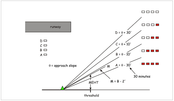
The PAPI system display provides visual indication of the pilot's [the pilot eye] position with respect to the established glideslope. The PAPI consists of 4 light units installed as a wingbar perpendicular to the runway edge with each unit having a different aiming angle as shown in Figure 1 below. The angles shown are those for a 3 degree approach slope.
Figure 1: PAPI Profile
Text version of Figure 1
-
With the use of 4 light units, the PAPI provides 5 sectors of information to the pilot for: too low, slightly low, on course, slightly high and too high.
Figure 2: PAPI Display
Text version of Figure 2
-
It should be noted that the pilot is not given indication of the approach slope itself, but that of an "approach corridor" defined by the angles C and B. The approach slope is mid-point of this corridor or (C+B)/2. Anywhere within the corridor, the pilot should see the same display of 2 reds and 2 whites.
3.2 Abbreviated Precision Approach Path Indicator
-
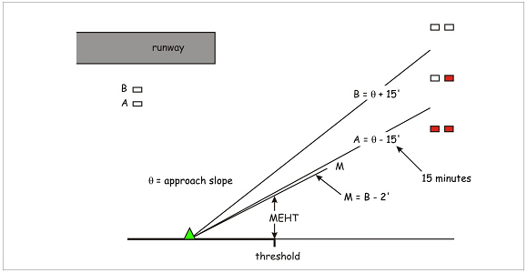
The APAPI consists of 2 light units also installed as a wingbar perpendicular to the runway edge with each unit having an aiming angle as shown in Figure 3 below for a 3 degree approach slope.
Figure 3: APAPI Profile
Text version of Figure 3
-
With the use of 2 light units, the APAPI provides 3 sectors of information to the pilot for: low, on course, and high.
Figure 4: APAPI Display
Text version of Figure 4
-
Each PAPI light unit has a lamp contained within a reflector, a red filter and one or more lenses.
-
A single lens unit is illustrated in Figure 5a. The reflector is parabolic and the rays of light beam are parallel within the unit, the top portion of the beam is coloured red by the filter. The lens causes a reversal of the beam such that beyond the focal point, the upper portion is now white and the lower portion red.
Figure 5a: PAPI Light Unit Ray Diagram – Single Lens
Text version of Figure 5a
-
And the case of the tandem lens PAPI is illustrated in Figure 5b.
Figure 5b: PAPI Light Unit Ray Diagram –Tandem Lens
Text version of Figure 5b
4.0 PREVENTIVE MAINTENANCE INSPECTION PROCEDURES
-
This section contains a Preventive Maintenance Inspection (PMI) schedule for the PAPI system with step-by-step instructions for performing the PMI. The PMIs establish a recommended routine which may be altered to suit local conditions. The manufacturer's operating and maintenance instructions should also be consulted as may be applicable to specific product designs.
Note: Except for item 16, this checklist may also be used for Visual Approach Slope Indicator (VAS)I systems.
Preventive Maintenance Inspection (PMI) Step-by-Step Schedule
| D | W | M | Q | SA | A | U | |
|---|---|---|---|---|---|---|---|
| 1. Check lamps/filters for operation. | X | ||||||
| 2. Check operation of controls | X | ||||||
| 3. Check for damage by service vehicles or aircraft. | X | ||||||
| 4. Clean lamps and filters. | X | ||||||
| 5. Check mechanical parts for damage | X | ||||||
| 6. Check lightning arresters | X | ||||||
| 7. Check for water damage or insect infestation. | X | ||||||
| 8. Check for presence of rodents | X | ||||||
| 9. Record output current and input voltage of adapter (if used). | X | ||||||
| 10. Check alignment and aiming of light boxes. | X | ||||||
| 11. Check levelling and operation of tilt switch. | X | ||||||
| 12. Check integrity of obstacle-free approach plane. | X | ||||||
| 13. Check insulation resistance of underground cables. | X | ||||||
| 14. Check resistance of grounding system. | X | ||||||
| 15. Check after heavy snowfall | X | ||||||
| 16. Check condensation/frost prevention system | X |
- D = Daily
- Q = Quarterly
- U = Unscheduled
- W = Weekly
- SA = Semi-Annual
- M = Monthly
- A = Annual
4.1 Daily Checks
-
Confirm all lamps are burning and appear to be of equal brightness.
-
Adequate spare lamps should be available to permit a complete replacement of all lamps in the system. Spare bypass fuses, if used, should also be stocked.
-
Lamps should be replaced immediately if they burn out or become darkened.
-
If the PAPI uses bypass fuses, never replace a lamp until the associated fuse is checked.
-
Confirm that the filters are properly aligned. This is done by bobbing your head whilst looking towards the front of the light unit.
CAUTION: This should be done at a lower brightness as the intensity at high brightness selection can be overwhelming.
4.1.1 Bobbing the PAPI – Transition Check
CAUTION: Although the transition is primarily that of the filter, its malfunction may also be due to other factors such as the positioning of the lamp. In as much as the filter is fragile, the rectification of other causes should be considered first.
-
When doing a check of the transition, the maintenance person "bobs" the front of the light unit by moving the head up and down.
-
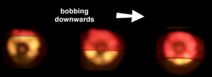
In the case of the tandem lens PAPI light unit, when bobbing downwards the virtual image of the filter will follow in unison moving downwards over the width of the lens, as shown in Figure 6. When the image of the filter is at the midpoint of the lens this is the datum of the light unit. The change from full white to full red is the transition.
Figure 6: Movement of the Filter Image with Bobbing
Text version of Figure 6
-
For a multi-lamp PAPI, each having a tandem lens system, the filters should be observed to transition their lenses simultaneously and in unison.
Figure 7a: Filters bob in unison
Text version of Figure 7a
Figure 7b: Filters do not bob in unison
Text version of Figure 7b
-
In the case of a single lens PAPI light unit, the image is somewhat different in that the red first appears as a point and then expand around the lens, as shown in Figure 8. What you are seeing is the virtual image of the filter cast on the surface of the lamp and reflector. Although this differs from the display of the tandem lens light unit, the progression of the transition from full white to full red can still be discerned.
Figure 8: Transition of a single lens PAPI
Text version of Figure 8
4.2 Monthly Checks
-
Check operation of controls. Check photocell brightness control and runway light circuit interlock (if used), radio control (if used), and/or remote control switch.
-
Check for damage by mowers, snowplows, etc.
-
Visually check mechanical parts for cleanliness, burned wires or connections, cracked insulators, lamps or filters, etc.
-
Check if the lightning arresters and/or surge suppressors are scorched or show other signs of being burned out, and replace as necessary. Also, check after electrical storms.
-
Check the lamp boxes and adapter units for damage or debris from water, mice, wasps, bird nests, spider webs, etc., and clean or repair as needed.
-
Check for burrows or other signs of rodent activity in vicinity of cables; take steps to discourage their presence to minimize likelihood of cable damage.
-
If an adapter unit is used, read and record the output current and the input voltage to the adapter unit.
-
Check the horizontal and lateral alignment of the light boxes, and check the aiming (vertical angle) with the PAPI aiming instrument. Record the angle setting and the date in a maintenance log. It is particularly important to check aiming frequently whenever the soil freezes or thaws or has a change in moisture content (especially clay soils).
-
Check levelling and operating of tilt switch - if applicable.
-
Check and verify the performance of frost/condensation prevention system, where installed.
4.3 Quarterly Checks
-
Check the Obstacle Protection Surface for clearance from tree growth, new towers, pole lines, or other obstacles.
-
Clean lamps and filters. Ensure that the lamp is properly positioned in the reflector.
-
Do so only if necessary. The least contact with filters and lamp the better. Do not touch the lamp or filters directly with bare fingers.
-
Improper positioning of the lamp can cause defocusing which results in an enlarged pinkish region between the white and the red colors. When PAPI units are subject to defocusing problems, flight check results may be affected by the uncertainty in determining the white-to-pink or pink-to-red transition.
-
In a typical PAPI unit model, the elevation error between the mechanical axis and the color transition may reach values of 14 minutes for 1mm of filter vertical misalignment.
4.4 Semi Annual Checks
-
Check insulation resistance of underground cables and record the results.
-
Check the resistance of the grounding system and record the results.
-
Verify the proper operation of the condensation/frost prevention means.
5.0 MAINTENANCE PROCEDURE
5.1 Adjustment of the Vertical Aiming
-
This adjustment is performed by using a clinometer. Clinometers are normally supplied with the PAPI or may be purchased from the PAPI manufacturer. Handle these precision instruments carefully. Make sure the aiming device is the one supplied with the PAPI light units.
-
Check the manufacturer's manual (supplied with the units) for the procedures used to check each PAPI unit for proper aiming angle.
-
Stand in front of the PAPI units (approximately 15m away) and check that the light changes color simultaneously along the whole width of each unit. If not, horizontal levelling was not done properly. Other causes such as the red filters being out of position, or the box being warped are possible but least likely.
-
Check the tilt switch on all units (where provided) by placing the small level on the marked top surface of the tilt switch and adjusting the tilt switch if necessary. If the tilt switch shuts off the power when it is level, the tilt switch should be replaced. The main switch may have to be toggled off and on to reset tilt switch circuit. For tolerances, refer to the manufacturer's installation manual.
5.2 Check of Adapter Unit Current Output
-
With system on, adjust day current to 6.4 to 6.6 amperes.
-
Cover photocell with a heavy glove or other dark material, wait for time delay to de energize, and read current. If the system has a night adjustment, set current to 4.8 to 5.0 amperes.
-
Remove covering from photocell. The lights should switch back to day brightness after a short time delay (15 seconds to 1 minute).
6.0 VERIFICATION OF PRECISION APPROCAH PATH INDICATOR (PAPI) SETTING ANGLES
- When the equipment is put initially into operation and at regular intervals thereafter, the setting angles of the PAPI light units should be verified by an independent method to validate the accuracy of the settings completed with the clinometer.
6.1 By Ground Survey Method
-
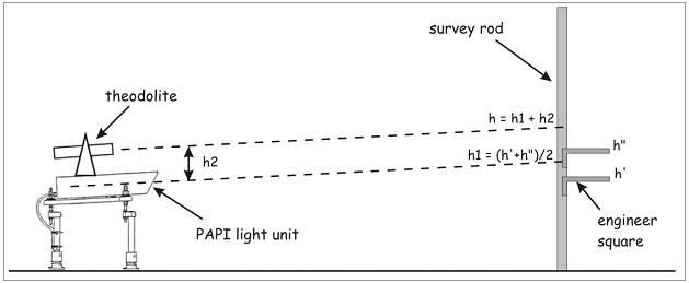
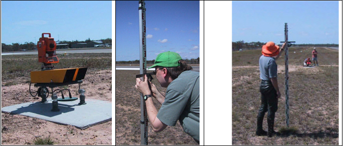
The survey method involves the use of a theodolite, surveyor's rod, and an engineer's square. The setup is illustrated in Figures 9 and 10.
Figure 9: Survey method – Setup
Text version of Figure 9
Figure 10: Survey Method
Text version of Figure 10
-
The method involves looking into the front of the PAPI light unit to observe the output display from full white to full red.
-
Step 1. Coordinate with Air Traffic Services (ATC) to obtain approval for access to the movement area and specifically to the PAPI light units. Inform ATC that they may be requested to turn on the PAPI at certain brightness levels. If the intensity cannot be reduced to a suitable value for observation, then dark glasses should be used.
-
Step 2. Using the PAPI maintenance kit [i.e. the clinometer], set the light units to the nominal setting angles.
-
Step 3. Select one of the PAPI light units and place the theodolite on the cover.
Note:. It may not be possible to place the theodolite on the top of the light unit. In such case, the theodolite should be positioned so that its reference point can be measured with respect to that of light unit.
-
Step 4. Determine the theodolite offset as the distance H2 as the distance to the theodolite from the light unit datum which is the bottom edge of the filter, or to the middle of the lens, or centre of the lamp filament. Typically this distance is of the order of 300mm.
-
Step 5. Pace out a distance of 20 to 30 paces from the light. For each projector, the observer should be able to see a white signal when standing, and a red signal when slightly stooped. An exactitude of distance is not of importance since the angle is obtained from the theodolite and not calculated. For a given height of observer, and level terrain, the shortest distance would be that of unit "D" which is the innermost light unit having the largest angle of 3.5 degrees for a 3 degree glidepath. Assuming a height of 0.6m for the light centre at the PAPI location, the distance for the innermost light unit would be about 16m. For a 5.5 degree glidepath and innermost unit at 6.0 degree angle the observer would be at about 9.5m.
Note: The observer should wear eye protection such as sunglasses as the PAPI light unit can produce significant glare. The brightness level should be adjusted for the lowest intensity [e.g. 2.8A] for which observation would be successful. If this is not possible and a higher intensity is selected, the observer may need to use welding goggles.
Welding goggles with a lifting flap at the front with clear glass in the body can be obtained from a local hardware store. A particular technique is to replace one of the clear lenses with green glass in which case the observer has the benefit of 1, 2 or 3 thickness of glass to look through
-
Step 6. Holding the survey rod in one hand, slide the engineer square up the rod to a point at which a white signal is obtained. Mark this point h".
Note: It is important not to move the staff once the marking has commenced.
-
Step 7 Holding the survey rod in one hand, slide the engineer square down the rod to a point at which a full red signal is obtained. Mark this point h'.
-
Step 8 Determine and mark the mid point, h1 = ( h' + h" )/2. This is the mid-point of the transition.
-
Step 9 Having established the observed mid-point of the transition, the observer then adds to that mark the distance of the offset measured at Step 4, and marks that point on the staff [h = h1 + h2]. Invariably this is above head height. The observer then holds the square such that the top edge is on the new mark, and the surveyor reads the angle. This angle is of a line parallel with the light unit datum and thus the setting angle.
-
Step 10 Using the theodolite sight and read directly the angle to the top of the square. Repeat by taking another reading using the "second face" of the theodolite, by rotating the transit 180 degrees and then revolving 180 degrees. Take the mean of both readings as the measured angle. This practice will null any theodolite set-up errors." Record the angles.
-
-
Expect coincidence of clinometer and theodolite readings within 3 minutes of arc, which is a reasonable tolerance. If there is a discrepancy, the following factors should be considered ...
-
Observer performance: try a different observer. Use the same observer for all lights of any system for consistency.
-
Intensity: An intensity that is too great will give consistently low observations.
-
Check settings: Re-apply the clinometer and check that the light is aimed correctly. The clinometer itself may need to be recalibrated following the manufacturer's instructions; however, this is an unlikely, albeit possible, cause for the error.
-
Lamps: Old lamps near the end of life may suffer filament sag, which de-focuses. Check that the lamp is positioned properly within the reflector.
-
Re-check measurements: The angle measurement is taken over a relatively short range. A slight error in measurement of the theodolite offset or marking the surveyor's rod can be significant to the end result.
-
Unit Structure: If other factors do not provide an answer, the light unit itself may have been damaged in transit or during installation
-
6.2 By Computer Image Analysis
-
The International Civil Aviation Organization (ICAO) - Visual Aids Working Group (VAWG) meeting held in Montréal in February 2009 and Osaka in October 2009, introduced the usage of computer image analysis systems for the accurate alignment of PAPI angles. This new class of equipment has been considered as the most accurate method for a more precise check of PAPI units setup, having regard that such equipment have shown an overall precision and accuracy response better than any other practice.
-
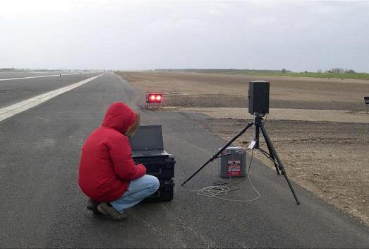
The computer image analysis method (see Figure.11), has the advantage of the ground survey method in that the measurement takes place on the ground in front of the PAPI light unit yet avoids any criticality due to the errors introduced by the manual measurement procedure at a short distance. The method is based on the external observation of the PAPI beam performed by a self moving sensor able to detect the colour transition. Since the sensor obtains its reference plane by means of a gravitational platform, this method is independent of the light unit and only measures the spatial location of the resulting light beam.
-
The equipment like the one shown in figure 10 enables re-positioning of the light unit with respect to the image of the filter at the mid-point of the lens. The image analysis software also reveals any problem in the PAPI projector including defocusing issues, while the transition angle of each beam in the unit is processed to give the final overall transition angle of the whole PAPI unit. The optoelectronic sensor can adjust itself to accommodate for the PAPI output intensity: accuracy and precision of the measurement are not affected by the positioning of the instrument so that the equipment of this method is easy to use and to deploy in the field. The sensor head is mounted on a auto levelling moving mechanism to compensate any roughness of terrain in front of the PAPI and is linked to a laptop and portable power station.
-
An additional advantage of this method is that it can also obtain photometric and chromaticity information to show conformance to standards. The angle measurement, within an accuracy better than 1 minute of arc, is available immediately including the instructions on how to correct the PAPI unit position if necessary.
-
The image analysis based equipment instrument shows the highest value of accuracy, repeatability and reproducibility of measurement, where the detection of transition is not left to the skill of the operator, rather to the capability of the equipment to always provide the same standard of quality of measurements, avoiding any additional element of uncertainty.
Figure 11 Equipment setup
Photo source. Argos
Text version of Figure 11
7.0 SUMMARY
-
The PAPI system is maintained to ensure that the units are set at the proper vertical angles for the associated glideslope. The setting angles are established and maintained by means of the aiming instrument [clinometer] and should be verified initially and at periodic intervals by an independent method.
8.0 RESPONSIBILITIES
-
It is aerodrome operators' responsibility to ensure that the PAPI or APAPI is correctly installed, inspected and maintained in accordance with published specifications of TP 312, manufacturers' specifications and recommended maintenance procedures; including the verification of the angle settings for the individual light units.
-
The PAPI system is maintained to ensure required light output and that the units are set at the proper vertical angles for the associated glideslope. The setting angles are established and maintained by means of the aiming instrument [clinometer] and should be verified initially and at periodic intervals to validate the accuracy of the settings established using the clinometer.
9.0 INFORMATION MANAGEMENT
- Not applicable.
10.0 DOCUMENT HISTORY
- Not applicable.
11.0 CONTACT OFFICE
For more information, please contact the:
TCCA Regional Office listed at the following address
https://tc.canada.ca/en/corporate-services/regions
Suggestions for amendment to this document are invited, and should be submitted via: AARTInfoDoc@tc.gc.ca
[Original signed by]
Aaron McCorie
Director, Standards
Civil Aviation
Transport Canada
Transport Canada documents or intranet pages mentioned in this document are available upon request through the Contact Office.
