AV 2000-05
5 October 2000
Aileron control column sprockets
Recently, the pilot of a privately owned 1970 Cessna 172L lost aileron control in flight when the control column (control 'U') right side control cable/chain sprocket, along with the right side control wheel tube, became disconnected from the control column. This resulted in the control chain falling off the sprocket which caused the entire aileron control cable circuit to become slack, leaving the pilot with no aileron control.
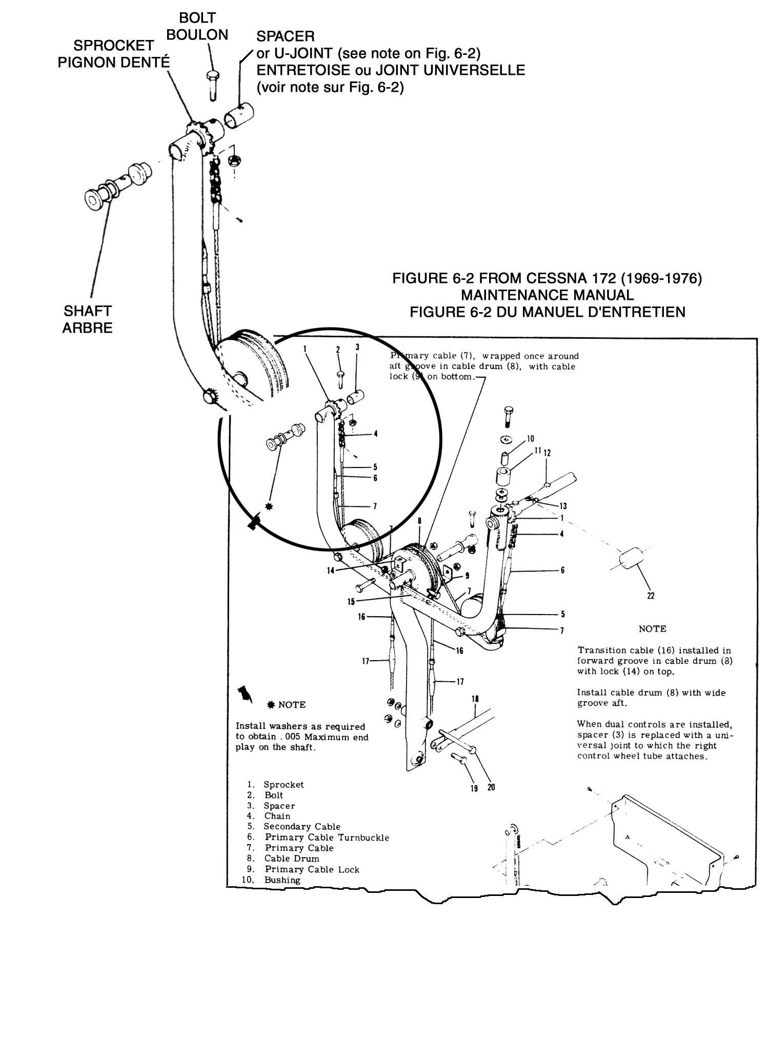
Shortly before the flight the owner had an AME replace the control tube U-joint. While reassembling the control system on the right side of the control column, the AME inadvertently displaced/pushed in the shaft used for mounting the sprocket to the column (see diagram). The control tube was then attached to the sprocket using the appropriate bolt. The bolt was inserted through the sprocket and control tube but not through the hole in the shaft. The sprocket appeared to be correctly installed because the bolt was secure and the sprocket remained mounted to the end of the shaft throughout the maintenance action. During the subsequent flight, the ailerons functioned normally until the pilot in the right seat attempted to control the aircraft, at which time the control tube and sprocket became detached from the end of the control column shaft, and aileron control was lost.
When assembling these parts, maintenance personnel should be careful to ensure all three components (the shaft, sprocket and control tube U-joint) are properly mated, such that the bolt engages the hole in each part. This task can be made difficult by restricted access to the work area. In particular, the right side view can be limited by the panel mounted map compartments and remote avionics installations such as blind encoders.
This configuration of control column and sprocket installation is found on various models of Cessna aircraft including:
- 172E and subsequent, including the new production 172R and S models
- R172K (Hawk XP)
- 172RG series
- 180H and subsequent
- 185D and subsequent
The maintenance manuals for these aircraft do not have detailed instructions for assembly of these parts. The manuals do, however, contain instructions for removal of the subject bolt and U-joint as part of the procedure for removal of the entire control 'U' assembly. Detailed reinstallation procedures for these parts, other than the often misused phrase "reverse the preceding steps for reinstallation", are not described in any of the manuals. The maintenance manual for the 1969 to 1976 172 series aircraft, has a note in figure 6-2, which indicates that a check should be made to verify that maximum end play of the shaft does not exceed 0.005 inch. The manuals for the other models contain the same basic maintenance information about removal and installation of the control column but do not contain the note referring to the shaft end play. Compounding the problem is the fact that these parts are replaced infrequently, and experience with this particular task would be limited even for AMEs with years of experience on these types.
Any defects or further occurrences should be reported by sending a Service Difficulty Report to Transport Canada, Continuing Airworthiness, Ottawa.
For further information, contact a Transport Canada Centre, or Mr. Mark Stephenson, Continuing Airworthiness, Ottawa, telephone (613) 952-4363, facsimile (613) 996-9178 or e-mail stephma@tc.gc.ca.
For Director, Aircraft Certification
B. Goyaniuk
Chief, Continuing Airworthiness
