
Table of contents
- Preamble
- Introduction
- Part A Mandatory criteria
- Part B Recommendations for ships engaged in certain types of operations, certain types of ships and additional guidelines
- Chapter 1 General
- Chapter 2 Recommended design criteria for ships engaged in certain types of operations and certain types of ships
- 2.1 Fishing vessels
- 2.2 Pontoons
- 2.3 Containerships greater than 100 m
- 2.4 Offshore supply vessels
- 2.5 Special purpose ships
- 2.6 Mobile offshore drilling units (modus)
- 2.7 Ships engaged in anchor handling operations
- 2.8 Ships engaged in towing and escort operations
- 2.9 Ships engaged in lifting operations
- 2.10 Sailing vessels
- 2.11 Cable ferries
- 2.12 Aquaculture barges
- 2.13 Dredgers, sand-suckers, open hopper barges
- Chapter 3 Guidance in preparing stability information
- 3.1 Effect of free surfaces of liquids in tanks
- 3.2 Permanent ballast
- 3.3 Assessment of compliance with stability criteria
- 3.4 Standard conditions of loading to be examined
- 3.5 Calculation of stability curves
- 3.6 Stability booklet
- 3.7 Operational measures for ships carrying timber deck cargoes
- 3.8 Operational and planning manuals for ships engaged in anchor handling for which section 2.7 applies
- 3.9 Operational and planning booklets for ships engaged in lifting for which section 2.9 applies
- 3.10 Operating booklets for certain ships
- Chapter 4 Stability calculations performed by stability instruments
- Chapter 5 Operational provisions against capsizing
- Chapter 6 Icing considerations
- Chapter 7 Considerations for watertight and weathertight integrity
- Chapter 8 Determination of lightship parameters
- Annex 1 Detailed guidance for the conduct of an inclining test
- Annex 2 Recommendations for skippers of fishing vessels on ensuring a vessel’s endurance in conditions of ice formation
- Annex 3 Recommended model for graphic or tabular presentation of permissible tensions for use in anchor handling operations
Preamble
The requirements concerning sufficient intact stability were first introduced in the Hull Construction Regulations for all vessels, with the exception of fishing vessels for which the requirements could be found in the Large Fishing Vessel Inspection Regulations and the Small Fishing Vessel Inspection Regulations, replaced in 2016 by the Fishing Vessel Safety Regulations. TP 7301: Stability, Subdivision and Load Line Standards was developed by Transport Canada in 1975, as a standard setting out conditions and criteria of approval for the purpose of the stability requirements prescribed by sections 80 and 81 of the Hull Construction Regulations. At the time, the standard was developed using the International Maritime Organization (IMO) Resolution A.167(ES.IV), Recommendation on intact stability for passenger and cargo ships under 100 metres in length, as amended by IMO Resolution A.206(VII), with Canadian modifications where appropriate.
In 1985, the IMO adopted Resolution A.562(14), Recommendation on a severe wind and rolling criterion (weather criterion) for the intact stability of passenger and cargo ships of 24 metres in length and over. This criterion supplements the stability criteria of A.167(ES.IV), as amended by IMO Resolution A.206(VII). It was recommended that the minimum stability of passenger and cargo vessels of 100 metres in length and over should comply with the weather criterion of the present recommendation in addition to other appropriate stability criteria to the satisfaction of the Administration.
Recognizing the need for the development of an internationally agreed upon code on intact stability for all types of vessels covered by IMO instruments, which would summarize the work carried out by the IMO so far, the IMO Assembly first adopted the International Code on Intact Stability for All Types of Ships Covered by IMO Instruments in 1993, amalgamating in a single document Resolution A.749(18). It was subsequently amended considering experience gained from its implementation. The IMO Resolution MSC.267(85), International Code on Intact Stability, 2008 (2008 IS Code), as amended by MSC.319(89), MSC.398(95), MSC.415(97), MSC.443(99) and MSC.444(99), was assembled and adopted by the IMO.
The mandatory TP 7301: Canadian Modifications to the International Code on Intact Stability, 2008, was developed in line with the Vessel Construction and Equipment Regulations (VCER). A vessel that complied with TP 7301: Stability, Subdivision and Load Line Standards (1975) prior to the date this second edition of TP 7301 and the VCER came into force can continue to do so until the first anniversary of the coming into force, as prescribed in section 10 of the VCER. After the first anniversary, the vessel is deemed to comply until it is subject to an alteration that affects its stability as per SOLAS Chapter II-1, regulation 5.4, or when the lightship survey required by SOLAS Chapter II-1, regulations 5.5 is due.
Notice
Information notes are for information only and do not form part of the Standard.
To ensure compliance, it is the responsibility of the reader to consult the official instrument, as amended, referred to in the text box.
Introduction
1 Purpose
1.1.1 The Canadian Modifications to the International Code on Intact Stability, 2008 (2008 IS Code) set out the modifications to the 2008 IS Code stability criteria for the safe operation of Canadian vessels and to minimize risks to the vessel, to the people on board, and to the environment.
2 Definitions
aquaculture barge means a floating workstation that is detached or integrated, with technical equipment for performing certain functions connected to fish farming, such as storage, feeding, electricity supply, crewing and monitoring of the site. (chaland d’aquaculture)
domestic voyage has the same meaning as in the Load Line Regulations. (voyage intérieur)
margin line means a line drawn at least 76 mm below the upper surface of the bulkhead deck at the side of a vessel and assumed for the purpose of determining the floodable length of the vessel. (ligne de surimmersion)
Part A Mandatory criteria
Chapter 1 General
1.1 Application
1.2 Dynamic stability phenomena in waves
Information note: Vessels that are subject to SOLAS should be assessed in accordance with IMO Circular MSC.1/Circ.1627, Interim Guidelines on the Second Generation Intact Stability Criteria for the verification of their dynamic stability failure modes in waves.
Chapter 2 General criteria
2.1 General
No modification.
2.2 Criteria regarding righting lever curve properties
2.2.1 Passenger vessels, ferries and vessels with barge type hulls that do not exceed near coastal voyages, Class 2, may have a limited range of stability that may not permit compliance with 2.2.2 and 2.2.3 of the 2008 IS Code. In these cases, alternate criteria may accept a righting lever curve with a maximum righting lever (GZ) value of less than 25° and having a righting lever (GZ) value at 30° less than 0.20 m provided that:
The range of the righting lever (GZ) curve is at least 40°.
The area under the righting lever (GZ) curve within its range, or to the angle of down-flooding, whichever is less, is at least 0.18 metre-radians.
2.2.2 For the purpose of 2.2.3 of the 2008 IS Code, for vessels for which the maximum righting arm occurs at an angle below 25°, the alternative criteria mentioned in Chapter 4 of IMO Circular MSC.1/Circ.1281, Explanatory Notes to the International Code on Intact Stability, 2008, can be applied for all types of voyages.
2.3 Severe wind and rolling criterion (weather criterion)
2.3.1 Section 2.3 of the 2008 IS Code does not apply to non-convention vessels that operate in sheltered waters or inland waters.
2.3.2 For the purpose of 2.3 of the 2008 IS Code, non-convention vessels of 24 m and not more than 45 m in length can use a reduced wind load, as indicated in Table 1.
Table 1
|
h (m) |
1 |
2 |
3 |
4 |
5 |
6 and over |
|---|---|---|---|---|---|---|
|
P (Pa) |
316 |
386 |
429 |
460 |
485 |
504 |
Where h is the vertical distance in metres (m) from the centre of the projected vertical area above the waterline to the waterline, and P is the wind pressure in Pascal (Pa).
Intermediate values in this table are to be obtained by linear interpolation.
2.3.3 For the purpose of 2.3 of the 2008 IS Code, non-convention vessels that operate on near coastal voyages, Class 2, can use the reduced wind pressure shown in Table 2Footnote 1 with a demonstration based on historical environmental conditions that the vessel’s area of operation has less severe weather conditions.
Table 2
|
Voyage duration |
Wind pressure in Pascal (Pa) |
|---|---|
|
Not more than 2 hours |
168 |
|
More than 2 hours |
269 |
Chapter 3 Special criteria for certain types of ships
3.1 Passenger ships
3.1.1 For the purpose of 3.1.1 of the 2008 IS Code, the following options can be used for existing vessels where construction began – as defined in section 1 of the VCER – on or before 31 July 2007, if the angle of heel on account of crowding of passengers exceeds 10°:
Option 1 – All existing vessels
-
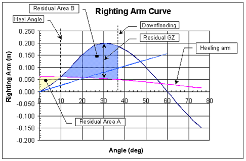
The angle of static heel, measured from the intersection of the righting lever (GZ) curve and the heeling arm, cannot exceed 14° nor immerse the margin line.
-
The residual area, between the curves of righting levers and passenger heeling arms, cannot be less than 0.018 + 0.2A40/df metre-radians, where A40/df is the total area under the righting arm curve up to 40° or the down-flooding angle, whichever is less.
-
The remaining righting lever must attain a value of at least 0.1 metre.
Option 2 – Existing vessels operating in sheltered waters
-
The angle of static heel, measured from the intersection of the righting lever (GZ) curve and the heeling arm curve, cannot exceed 14° and the remaining freeboard cannot be less than 50% of the upright freeboard.
or
The angle of static heel, measured from the intersection of the righting lever (GZ) curve and the heeling arm curve, cannot exceed 14° or immerse the margin line.
-
The residual area, between the curves of righting levers and passenger heeling arms, cannot be less than 0.025 metre-radians.
or
The residual area ratio (area B /area A) cannot be less than 1.0, where area B is between the curves of the righting lever and the passenger heeling arm, measured between the angle of static heel and 40° or the down-flooding angle, whichever is less. Area A is the residual area between the curves of the passenger heeling arm and the righting lever up to the angle of static heel.
- The remaining righting lever must attain a value of at least 0.1 metre.
Whenever the angle of static heel exceeds 10°, the following conditions must also be met:
- Secure all cargo, including deck cargo, against shifting.
- Provide seating for all passengers.
- Secure any furniture that is being used or stowed.
- Provide sufficient grab rails in spaces that normally accommodate persons.
- Arrange decks and deck surfaces to reduce slipping hazards.
3.1.2 For the purpose of 3.1.1.1 of the 2008 IS Code, if the vessel operates in temperature below 0°C, winter clothing (2.8 kg per person) must be added for each person.
3.1.3 For the purpose of 3.1.1.1 of the 2008 IS Code, vessels travelling for more than six hours or at night must factor-in personal items and carry-on luggage (an additional 6 kg per person).
3.2 Oil tankers of 5,000 tonnes deadweight and above
No modification.
3.3 Cargo ships carrying timber deck cargoes
No modification.
Information note: Refer to the Cargo, Fumigation and Tackle Regulations, Part 1, Division 4, for requirements applicable to vessels carrying timber on an uncovered part of the freeboard deck or superstructure deck.
3.4 Cargo ships carrying grain in bulk
No modification.
Information note: Refer to the Cargo, Fumigation and Tackle Regulations, Part 1, Division 3, for requirements applicable to vessels loading or carrying grain in bulk.
3.5 High-speed craft
No modification.
Part B Recommendations for ships engaged in certain types of operations, certain types of ships and additional guidelines
Chapter 1 General
1.1 Purpose
No modification.
Information Note: Part B is mandatory, as stated in section 101 of the Vessel Construction and Equipment Regulations.
1.2 Application
Chapter 2 Recommended design criteria for ships engaged in certain types of operations and certain types of ships
2.1 Fishing vessels
No modification.
2.2 Pontoons
No modification.
Information Note: Section 2.2.1 of the 2008 IS Code applies to vessels that do not have mechanical means of propulsion that meet the criteria set out in 2.2.1.1 to 2.2.1.6 of the 2008 IS Code.
Oil tankers of 5,000 tonnes deadweight and above to which section 12 of the Vessel Pollution and Dangerous Chemicals Regulations applies must comply with the requirements of regulation 27 of Annex I to MARPOL 73/78.
2.3 Containerships greater than 100 m
No modification.
2.4 Offshore supply vessels
No modification.
2.5 Special purpose ships
No modification.
2.6 Mobile offshore drilling units (MODUs)
No modification.
2.7 Ships engaged in anchor handling operations
No modification.
2.8 Ships engaged in towing and escort operations
No modification.
2.9 Ships engaged in lifting operations
No modification.
2.10 Sailing Vessels
2.10.1 Sailing vessels must comply with Part A of the 2008 IS Code while on powered mode.
2.10.2 In addition to the criteria of Part A, sailing vessels must comply with stability criteria under sail appropriate for the vessel size, voyage and number of persons on board, in accordance with one of the following standards:
- The stability criteria for sailing vessels in the United States Code of Federal Regulations (CFR) 46 Part 171;
- The stability criteria for sailing vessels in the Passenger Yacht Code Part B, published by the Red Ensign Group;
- The criteria for sailing vessels in the National Standard for Commercial Vessels Part C Section 6 Subsection 6A – Intact Stability Requirements published by the Australian Marine Safety Authority;
- ISO 12217-2 – Small craft — Stability and buoyancy assessment and categorization — Part 2: Sailing boats of hull length greater than or equal to 6 m; or
- The stability criteria for sailing vessels published by a Canadian Recognized Organization.
2.11 Cable Ferries
2.11.1 Ferries operated on a cable must comply with the stability requirements of Part A.
2.12 Aquaculture Barges
2.12.1 Instead of complying with the requirements of Part A of the 2008 IS Code and TP 7301, aquaculture barges with persons on board can comply with the raft stability requirements in section 10.3 of the Norwegian Standard NS 9415 Marine fish farms requirements for site survey, risk analyses, design, dimensioning, production, installation and operation.
2.13 Dredgers, Sand-suckers, Open Hopper barges
2.13.1 Performance-based intact stability calculations may be accepted for intact stability as an alternative to issue reduced freeboard with an International Load Line Exemption Certificate for dredgers and similar vessels, based on the Guidelines for the Assignment of Reduced Freeboards for Dredgers, DR-68.
Chapter 3 Guidance in preparing stability information
3.1 Effect of free surfaces of liquids in tanks
No modification.
3.2 Permanent ballast
3.2.1 For the purpose of the 3.2 of the 2008 IS Code:
- Permanent ballast must be shown as a separate item in the vessel’s lightship condition.
- Operating conditions must include permanent ballast in the vessel’s lightship condition.
- A sketch indicating the weight, position, description and securing arrangement of the vessel’s permanent ballast and must be included in the stability booklet.
- Use of fuel as permanent ballast to fulfil the stability requirements is not permitted.
Information Note: When buoyant material is used it must meet the requirements of section 316 of the Vessel Fire Safety Regulations.
3.3 Assessment of compliance with stability criteria
No modification.
3.4 Standard conditions of loading to be examined
No modification.
3.5 Calculation of stability curves
No modification.
3.6 Stability booklet
3.6.1 For the purpose of 3.6 of the 2008 IS Code, in all tables or diagrams, the scale of draughts or displacements must be extended to factor-in the entrapped water to the full load displacement where pipes are carried on deck as cargoes and the increase displacement due to ice accretion, as applicable.
3.6.2 The stability booklet must be written in the working language of the vessel.
3.7 Operational measures for ships carrying timber deck cargoes
No modification.
3.8 Operational and planning manuals for ships engaged in anchor handling for which section 2.7 applies
No modification.
3.9 Operational and planning booklets for ships engaged in lifting for which section 2.9 applies
No modification.
3.10 Operating booklets for certain ships
No modification.
Chapter 4 Stability calculations performed by stability instruments
4.1 Stability instruments
4.1.1 For the purpose of 4.1 of the 2008 IS Code, stability instruments that are fitted on vessels to supplement stability booklets must be approved by a Canadian recognized organization or Transport Canada.
Chapter 5 Operational provisions against capsizing
5.1 General precautions against capsizing
No modification.
5.2 Operational precautions in heavy weather
No modification.
5.3 Ship handling in heavy weather
No modification.
Chapter 6 Icing considerations
6.1 General
6.1.1 For the purpose of 6.1 of the 2008 IS Code, all vessels operating during wintery monthsFootnote 2 in the sea area defined in 6.3.2.2 of the 2008 IS Code must use an ice accretion load in accordance with 6.3.1 of 2008 IS Code.
6.2 Cargo ships carrying timber deck cargoes
No modification.
6.3 Fishing vessels
No modification.
6.4 Offshore supply vessels 24 m to 100 m in length
6.4.1 Offshore supply vessels operating where severe ice accretion can be expected – as defined in 6.3.2.2 of the 2008 IS Code – that are on station during wintery months for operations such as diving, research surveys, and stand by services must use the following ice accretion loads for stability calculations:
- 54 kg/m2 of total deck area or area carrying deck cargo, including the superstructure and deckhouse tops exposed to weather.
- 37 kg/m2 of area exposed to weather in the case of the superstructure and deckhouse fronts, and the deckhouse sides and bulwarks. This includes the area of the deckhouse sides and bulwarks on both sides of the vessel except that only the inboard surfaces can be used to calculate the bulwark areas.
- 78 kg/m2 of area, taking into consideration the overall block dimensions of the guardrails and stanchions, hatch coamings, companionways and vessel fittings exposed to weather.
- 48 kg per running metre in the case of rigging, masts, derricks and similar high objects measured to a height of 6.1 m above the main weather deck.
Chapter 7 Considerations for watertight and weathertight integrity
7.1 Hatchways
No modification.
7.2 Machinery space openings
No modification.
7.3 Doors
No modification.
7.4 Cargo ports and other similar openings
No modification.
7.5 Sidescuttles, window scuppers, inlets and discharges
No modification.
7.6 Other deck openings
No modification.
7.7 Ventilators, air pipes and sounding devices
No modification.
7.8 Freeing ports
No modification.
7.9 Miscellaneous
No modification.
Chapter 8 Determination of lightship parameters
8.1 Application
8.1.1 For the purpose of 8.1.5 of the 2008 IS Code, for vessels of not more than 24 metres in length, the periodic lightweight survey can be replaced by a declaration signed by the authorized representative or the Master of the vessel. This declaration must include – in table format – all the changes made to the vessel since the last inclining, with a description of the changes and weight and centre of gravity information. This declaration must also be accompanied by any available relevant information, such as photographs, sketches, etc. If the variation in lightship displacement exceeds 2% or the variation in centre of gravity may have a negative impact on the stability of the vessel, the vessel’s stability in the worst intact and damage conditions must be re-evaluated to demonstrate that the stability remains adequate for the vessel to perform its intended operation .
8.1.2 The declaration referred in paragraph 8.1.1 can be used on vessels up to 50 metres in length, provided that:
- The vessel is not subject to SOLAS;
- The vessel has not undergone repairs, alterations of modification of a major character; and
- All the applicable stability criteria, in the intact and damage stability conditions, are exceeded by at least 50%.
8.2 Preparations for the inclining test
No modification.
8.3 Plans required
No modification.
8.4 Test procedure
No modification.
8.5 Inclining test for MODUs
No modification.
8.6 Stability test for pontoons
No modification.
Annex 1 Detailed guidance for the conduct of an inclining test
No modification.
Annex 2 Recommendations for skippers of fishing vessels on ensuring a vessel’s endurance in conditions of ice formation
No modification.
Annex 3 Recommended model for graphic or tabular presentation of permissible tensions for use in anchor handling operations
No modification.