
Subject: Certification of Automatic Dependent Surveillance – Broadcast (ADS-B)
| Issuing Office: | Civil Aviation, Standards |
|---|---|
| Document No.: | AC 500-029 |
| File Classification No.: | Z 5000-34 |
| Issue No.: | 03 |
| RDIMS No.: | 21185462 – V6 |
| Effective Date: | 2026-06-15 |
Table of contents
- 1.0 Introduction
- 2.0 References and requirements
- 3.0 Background
- 4.0 Necessary documentation
- 5.0 ADS-B Out System Installation Guidance
- 6.0 Means of compliance (MoC)
- 7.0 Document history
- 8.0 Contact us
- Appendix A — Message Element Descriptions
- Appendix B — Identifying and Qualifying ADS-B Position Sources
- Appendix C — Latency Analysis
- Appendix D — TCCA/FAA/EASA ADS-B Out Parameters Comparison
- Appendix E — Comparison Between TCCA AC 500-029 Issue 3 and FAA AC 20-165B
1.0 Introduction
(1) This Advisory Circular (AC) is provided for information and guidance purposes. It describes an example of an acceptable means, but not the only means, of demonstrating compliance with regulations and standards. This AC on its own does not change, create, amend, or permit deviations from regulatory requirements, nor does it establish minimum standards.
1.1 Purpose
(1) This AC provides guidance for the initial installation and airworthiness approval of Automatic Dependent Surveillance - Broadcast (ADS-B) OUT equipment in aircraft. Specifically, it is to be read in the context of an application for a design approval such as a Type Certificate (TC), Amended Type Certificate (Amended TC) or Supplemental Type certificate (STC). For simplicity, throughout this document, the term “applicant” refers to an applicant for a design approval of an ADS-B Out system installation, unless otherwise indicated.
(2) This AC is intended for installations compliant with section 551.103 of Chapter 551 of the Airworthiness Manual (AWM). Airworthiness compliance will be evaluated based on the applicable intended function rule (such as subchapters 523.2505, 525.1301, 527.1301, or 529.1301) recognizing that the intended function is to meet the equipment requirements of section 551.103 of Chapter 551 of the AWM (AWM 551.103). It is understood that these installations are intended to meet the operating rules of Canada in the applicable airspace.
(3) It is possible to receive airworthiness approval for the installation of your ADS-B Out system with a different intended function. For example, operators may choose to equip with an ADS-B Out system although such an installation is not required according to operational rules in Canada. The installation may also be intended to comply with ADS-B Out requirements in foreign non-radar airspace [for example, European Union Aviation Safety Agency (EASA) Certification Specifications (and Acceptable Means of Compliance) for Airborne Communication, Navigation and Surveillance (CS ACNS) CS-ACNS.D.ADSB or Federal Aviation Administration (FAA) Code of Federal Regulations (CFR) 14 CFR §§ 91.225 and 91.227]. This AC does not address these types of installation. However, some aspects of this AC may be relevant to these types of installation. The applicant should propose appropriate means of compliance to Transport Canada Civil aviation (TCCA) for these specific intended functions.
1.2 Applicability
(1) This document applies to all TCCA employees, to individuals and organizations when they are exercising privileges granted to them under an External Ministerial Delegation of Authority. This information is also available to the aviation industry for information purposes.
1.3 Description of changes
(1) This revision includes the following changes:
- (a) Replace all instances of “ADS-B OUT” in the document with “ADS-B Out”
- (b) Replace all instances of “NAV Canada” and “Nav Canada” in the document with “NAV CANADA”.
- (c) Replace all instances of “installer” in the document with “applicant” and clarify in section 1.1(1) that the term applicant refers to an applicant for a design approval of an ADS-B Out installation.
- (d) Split and reword paragraphs (2) and (3) of section 1.1 to further clarify that this AC addresses installations intended to comply with AWM 551.103.
- (e) Paragraph 2.3: add definition for Probability of Update (PU).
- (f) Update Paragraph 4.3(6) to remove reference to FAA AC 43-6 and refer to Standard 571 for testing of altitude reporting equipment.
- (g) Add paragraph (7) to section 4.3 - Instructions for Continued Airworthiness, to add testing recommendations to avoid nuisance signals during equipment testing.
- (h) Update note in paragraph 6.2(1) to add the use of antenna shielding during test.
- (i) Paragraph 6.4(11): change the Probability of Update (PU) interval from 5s to 8s in the flight test pass criteria and update pass criterion to 96%.
- (j) Paragraph 6.4 (12): add a note recommending specific location or time of flight testing to avoid high traffic areas and reliance on comparative analysis after flight test.
2.0 References and requirements
2.1 Reference documents
(1) It is intended that the following reference materials be used in conjunction with this document:
- (a) Subpart 21 of Part V of the Canadian Aviation Regulations (CARs) — Approval of the Type Design or a Change to the Type Design of an Aeronautical Product, 1 December 2009;
- (b) CAR Standard 625 – Aircraft Equipment and Maintenance Standard
- (c) CAR Standard 571 - Maintenance
- (d) Advisory circular (AC) 513-003, Flight Test Considerations for the Approval of the Design of Aircraft Modifications Issue 01, 1 December 2004;
- (e) AC 700-009, Automatic Dependent Surveillance – Broadcast Issue 03, 2 July 2021;
- (f) FAA AC 20-165B, Airworthiness Approval of Automatic Dependent Surveillance - Broadcast Out Systems, 7 December 2015;
- (g) EASA CS-ACNS. Certification Specifications (and Acceptable Means of Compliance) for Airborne Communication, Navigation and Surveillance (CS-ACNS), 17 December 2013;
- (h) EASA AMC 20-24. Certification Considerations for the Enhanced ATS in Non-Radar Areas using ADS-B Surveillance (ADS-B-NRA) Application via 1090 MHz Extended Squitter, 25 April 2008;
- (i) TSO-C166b. Extended Squitter Automatic Dependent Surveillance – Broadcast (ADS-B) and Traffic Information Service – Broadcast (TIS-B) Equipment Operating on the Radio Frequency 1090 Megahertz (MHz), 02 December 2009;
- (j) TSO-C195b. Avionics Supporting Automatic Surveillance – Broadcast (ADS-B) Aircraft Surveillance Applications (ASA), 29 September 2014;
- (k) RTCA/DO-260B. Minimum Operational Performance Standards for 1090 MHz Extended Squitter Automatic Dependent Surveillance-Broadcast (ADS-B) and Traffic Information Services-Broadcast (TIS-B), Section 2, 2 December 2009;
- (l) Designated Airspace Handbook (TP 1820E);
- (m) FAA policy letter PL-105 Rev 4 MMEL Policy Letter – Web access at https://drs.faa.gov/browse/excelExternalWindow/DRSDOCID182159191520230120192510.0001;
- (n) FAA AC 25.1322-1, Flight crew Alerting;
- (o) FAA AC 27-1B, Certification of Normal Category Rotorcraft;
- (p) FAA AC 29-2C, Certification of Transport Category Rotorcraft; and
- (q) FAA AC 20-172(), Airworthiness Approval for ADS-B In Systems and Applications.
2.2 Cancelled documents
(1) By default, it is understood that the publication of a new issue of a document automatically renders any earlier issues of the same document null and void.
2.3 Definitions and abbreviations
(1) The following definitions are used in this document:
- (a) ADS-B IN: Receipt, processing, and display of other aircraft’s ADS-B transmissions. ADS-B IN is necessary to use airborne applications;
- (b) ADS-B Out: Transmission of an aircraft’s position, altitude, velocity, and other information to other aircraft and ATC ground-based surveillance systems;
- (c) Area Navigation (RNAV): A method of navigation that permits aircraft operation on any desired flight path within the coverage of station-referenced navigation aids or within the limits of the capability of self-contained aids, or a combination of these;
- (d) Automatic Dependent Surveillance: Rebroadcast (ADS-R). Retransmission of UAT ADS-B messages from aircraft on the 1090ES link and 1090ES messages on the UAT link. ADS-R ensures aircraft equipped with different links can receive messages from one another when equipped with ADS-B IN;
- (e) Automatic Dependent Surveillance Broadcast (ADS-B): An advanced surveillance technology where ADS-B Out equipped aircraft share position, altitude, velocity, and other information with ATC and other appropriately equipped aircraft;
- (f) Barometric Altitude Integrity Code (NICBARO): Indicates if pressure altitude is provided by a single Gillham encoder or another, more robust altitude source. Because of the potential for an undetected error in a Gillham encoding, many Gillham installations are cross-checked against a second altitude source. NICBARO annotates the status of this cross-check;
- (g) Flight Information System: Broadcast (FIS-B). A ground broadcast service provided over the UAT data link. The FAA FIS-B system provides pilots and flight crews of properly equipped aircraft with a cockpit display of certain aviation weather and aeronautical information;
- (h) Flight Manual: A generic term used throughout this AC to represent the AFM, RFM, AFM supplement, or RFM supplement;
- (i) Galileo: A European satellite-based radio navigation system being developed that will provide a global positioning service;
- (j) Global Navigation Satellite System (GNSS): The generic term for a satellite navigation system, such as GPS, that provides autonomous worldwide geo-spatial positioning and may include local or regional augmentations;
- (k) Global Positioning System (GPS): A U.S. satellite-based radio navigation system that provides a global positioning service. The service provided by GPS for civil use is defined in the Global Positioning System Standard Positioning Service Performance Standard, 4th edition, dated September 2008, available at http://www.gps.gov/technical/ps/2008-SPS-performance-standard.pdf;
- (l) GNSS Time of Applicability: The time when the position output from the GNSS sensor is applicable;
- (m) GNSS Time of Measurement (TOM): The time when the last GNSS signal used to determine the position arrives at the aircraft GNSS antenna:
- (n) Horizontal Figure of Merit (HFOM): The radius of a circle in the horizontal plane, with its center being at the true position, that describes the region assured to contain the indicated horizontal position with at least 95 percent probability under fault-free conditions at the time of applicability:
- (o) Horizontal Protection Level Fault Detection (HPLFD): The radius of a circle in the horizontal plane, with its center being at the true position, that describes the region assured to contain the indicated horizontal position. HPLFD is a horizontal region where the missed alert and false alert requirements are met for the chosen set of satellites when autonomous fault detection is used. It is a function of the satellite and user geometry and the expected error characteristics; it is not affected by actual measurements. Its value is predictable given reasonable assumptions regarding the expected error characteristics;
- (p) Horizontal Protection Level Fault Free (HPLFF): Fault-free horizontal protection level. Refer to RTCA/DO-229D, appendix R:
- (q) Mode Control Panel (MCP): contains controls that allow aircrew to interface with the autopilot system. The MCP can be used to instruct the autopilot to perform tasks such as; hold a specific altitude, change altitudes at a specific rate, hold a specific heading, turn to a new heading, and or follow the directions of a flight management computer. The MCP is not the autopilot, it just controls the mode in which the autopilot operates;
- (r) Navigation Accuracy Category for Position (NACp): Used to indicate, with 95 percent certainty, the accuracy of the aircraft reported horizontal position. Table 1 provides a list of possible NACp values. A NACp of 8 or greater is required by section 551.103 of Chapter 551 of the AWM;
|
Value |
Horizontal Accuracy Bound (Estimated Position Uncertainty) |
|---|---|
|
0 |
EPU ≥ 18.52 km (10.0 nm) |
|
1 |
EPU < 18.52 km (10.0 nm) |
|
2 |
EPU < 7.408 km (4.0 nm) |
|
3 |
EPU < 3.704 km (2.0 nm) |
|
4 |
EPU < 1.852 m (1.0 nm) |
|
5 |
EPU < 926 m (0.5 nm) |
|
6 |
EPU < 555.6 m (0.3 nm) |
|
7 |
EPU < 185.2 m (0.1 nm) |
|
8 |
EPU < 92.6 m (0.05 nm) |
|
9 |
EPU < 30 m |
|
10 |
EPU < 10 m |
|
11 |
EPU < 3 m |
- (s) Navigational Accuracy Category for Velocity (NACV): Used to indicate, with 95 percent certainty, the accuracy of the aircraft reported horizontal velocity. Table 2 provides a list of possible NACV values. A NACV of 1 or greater is required by section 551.103 of Chapter 551 of the AWM;
|
Value |
Horizontal Accuracy Bound (Estimated Velocity Uncertainty) |
|---|---|
|
0 |
≥ 10 m/s or unknown |
|
1 |
< 10 m/s |
|
2 |
< 3 m/s |
|
3 |
< 1 m/s |
|
4 |
< 0.3 m/s |
- (t) Navigation Integrity Category (NIC): A parameter that specifies an integrity containment radius. Table 3 provides a list of possible NIC values. A NIC of 7 or greater is required by section 551.103 of Chapter 551 of the AWM;
|
Value |
Radius of Containment |
|---|---|
|
0 |
unknown |
|
1 |
RC < 37.04 km (20.0 nm) |
|
2 |
RC < 14.816 km (8.0 nm) |
|
3 |
RC < 7.408 km (4.0 nm) |
|
4 |
RC < 3.704 km (2.0 nm) |
|
5 |
RC < 1.852 km (1.0 nm) |
|
6 Sup A=1 Sup B=1 |
RC < 1.111 km (0.6 nm) |
|
6 Sup A=0 Sup B=0 |
RC < 926 m (0.5 nm) |
|
6 Sup A=0 Sup B=1 |
RC < 555.6m (0.3 nm) |
|
7 |
RC < 370.4 m (0.2 nm) |
|
8 |
RC < 185.2 m (0.1 nm) |
|
9 |
RC < 75 m |
|
10 |
RC < 25 m |
|
11 |
RC < 7.5 m |
- (u) Position Source: The on-board avionics equipment that provides the latitude, longitude, geometric altitude, velocity, position and velocity accuracy metrics, and position integrity metric. Additionally, the position source may provide the vertical rate parameters;
- (v) Probability of Update (PU): Probability that an ADS-B Out message containing a set of mandatory valid parameters is received during the specified update interval.
- (w) Receiver Autonomous Integrity Monitoring (RAIM): Any algorithm that verifies the integrity of the position output using GPS measurements, or GPS measurements and barometric aiding, is considered a RAIM algorithm. An algorithm that uses additional information (such as a multi-sensor system with inertial reference system) to verify the integrity of the position output may be acceptable as a RAIM equivalent. Within this AC, the term RAIM is a synonym for aircraft-based augmentation system (ABAS) and is used to refer to both RAIM and RAIM-equivalent algorithms;
- (x) Satellite-Based Augmentation System (SBAS): A wide coverage augmentation system in which the user receives augmentation information from a satellite-based transmitter. In the United States, this is referred to as Wide Area Augmentation System (WAAS);
- (y) Selective Availability (SA): A protection technique employed by the Department of Defense that degraded GPS accuracy. Selective availability was discontinued on May 1, 2000;
- (z) Source Integrity Level (SIL): The probability of the reported horizontal position exceeding the radius of containment defined by the NIC without alerting, assuming the avionics has no faults. Table 4 provides a list of possible SIL values. A SIL of 3 is required by section 551.103 of Chapter 551 of the AWM;
|
Value |
Probability |
|---|---|
|
0 |
> 1x10⁻³ or unknown |
|
1 |
≤ 1x10⁻³ |
|
2 |
≤ 1x10⁻⁵ |
|
3 |
≤ 1x10⁻⁷ |
- (aa) System Design Assurance (SDA): The failure condition that the position transmission chain is designed to support. Table 5 provides a list of possible SDA values. An SDA of 2 or greater is required by section 551.103 of Chapter 551 of the AWM. Refer to paragraph 8.0(5)(b) of appendix A for more information;
| Value | Probability of Undetected Fault Causing the Transmission of False or Misleading Information |
|---|---|
|
0 |
> 1x10⁻³ or unknown |
|
1 |
≤ 1x10⁻³ |
|
2 |
≤ 1x10⁻⁵ |
|
3 |
≤ 1x10⁻⁷ |
- (bb) Total Latency: The total time between when the position is measured by the position source: GNSS time of measurement (TOM) for GNSS systems, and when the position is transmitted from the aircraft: ADS-B time of transmission;
- (cc) Traffic Collision Avoidance System (TCAS): Collision Avoidance systems which rely on transponder interrogations and replies of other airborne aircraft;
- (dd) Traffic Collision Avoidance System I: TCAS I is the first generation of collision avoidance technology. TCAS I systems are able to monitor the traffic situation around an aircraft and offer information on the approximate bearing and altitude of other aircraft. It can also generate collision warnings in the form of a "Traffic Advisory" (TA). The TA warns the pilot that another aircraft is in near vicinity, announcing "Traffic, traffic", but does not offer any suggested remedy;
- (ee) Traffic Collision Avoidance System II: TCAS II is the second and current generation of instrument warning TCAS. It offers all the benefits of TCAS I, but also offers the pilot direct, vocalized instructions to avoid danger, known as a "Resolution Advisory" (RA). TCAS II systems coordinate their resolution advisories before issuing commands to the pilots, so that if one aircraft is instructed to descend, the other will typically be told to climb — maximizing the separation between the two aircraft;
- (ff) Traffic Information Service - Broadcast (TIS-B): is a ground broadcast service provided from an ADS-B ground system network over the UAT and 1090ES links that provides position, velocity, and other information on traffic detected by a secondary surveillance radar but is not transmitting an ADS-B position;
- (gg) Uncompensated Latency: Any latency in the ADS-B system that is not compensated through extrapolation. Uncompensated latency can be represented as the difference between the time of applicability of the broadcast position and the actual time of transmission; and
- (hh) Wide Area Augmentation System (WAAS): The U.S. implementation of SBAS.
(2) The following abbreviations are used in this document:
- (a) 14 CFR: Title 14 of the Code of Federal Regulations;
- (b) 1090ES : 1090MHz Extended Squitter;
- (c) AC: Advisory Circular;
- (d) ACO: Aircraft Certification Office;
- (e) ACR: ADS-B Aircraft Operation Compliance Report;
- (f) ADIRS: Air Data and Inertial Reference System;
- (g) ADIRU: Air Data and Inertial Reference Unit;
- (h) ADS-B: Automatic Dependent Surveillance – Broadcast;
- (i) ADS-R: Automatic Dependent Surveillance – Rebroadcast;
- (j) A/FD: Airport/Facility Directory;
- (k) AFM: Airplane Flight Manual;
- (l) AFMS: Airplane Flight Manual Supplement;
- (m) ANSP: Air Navigation Service Provider;
- (n) ARINC: Aeronautical Radio, Incorporated;
- (o) ARP: Aerospace Recommended Practice;
- (p) ASA: Aircraft Surveillance Applications;
- (q) ASDE-X: Airport Surface Detection Equipment, Model X;
- (r) ATC: Air Traffic Control;
- (s) ATCRBS: Air Traffic Control Radar Beacon System;
- (t) AWM: Airworthiness Manual;
- (u) dB: Decibel;
- (v) CAR: Canadian Aviation Regulations;
- (w) CFR: Code of Federal Regulations;
- (x) CS: Certification Standards;
- (y) CS-ACNS: Certification Specifications (and Acceptable Means of Compliance) for Airborne Communication, Navigation and Surveillance;
- (z) DAH: Designated Airspace Handbook;
- (aa) DAPR: Detailed ADS-B Performance Report;
- (bb) DME: Distance Measuring Equipment;
- (cc) EASA: European Union Aviation Safety Agency;
- (dd) EMC: Electro Magnetic Compatibility;
- (ee) EMI: Electromagnetic Interference;
- (ff) EPU: Estimated Position Uncertainty;
- (gg) ERP: Effective Radiated Power;
- (hh) FAA: Federal Aviation Administration;
- (ii) FCU: Flight Control Unit;
- (jj) FHA: Functional Hazard Assessment;
- (kk) FIS-B: Flight Information Services – Broadcast;
- (ll) Flight ID: Flight Identification;
- (mm) FMS: Flight Management System;
- (nn) GB: Ground Based;
- (oo) GBAS: Ground Based Augmentation System;
- (pp) GNSS: Global Navigation Satellite System;
- (qq) GNSS/IRS: Global Navigation Satellite System/Inertial Reference System;
- (rr) GPS: Global Positioning System;
- (ss) GVA: Geometric Vertical Accuracy;
- (tt) HAE: Height Above Ellipsoid;
- (uu) HAG: Height Above Geoid;
- (vv) HFOM: Horizontal Figure of Merit;
- (ww) HIL: Horizontal Integrity Level;
- (xx) HPL: Horizontal Protection Level;
- (yy) HUL: Horizontal Uncertainty Level;
- (zz) Hz: Hertz;
- (aaa) ICAO: International Civil Aviation Organization;
- (bbb) ICA: Instructions for Continued Airworthiness;
- (ccc) IFR: Instrument Flight Rules;
- (ddd) INS: Inertial Navigation System;
- (eee) IRS: Inertial Reference System;
- (fff) IRU: Inertial Reference Unit;
- (ggg) kts: Knots;
- (hhh) LPV: Localizer Performance with Vertical Guidance;
- (iii) m/s: Meters per second;
- (jjj) ms: Milli-seconds;
- (kkk) MCP: Mode Control Panel;
- (lll) MHz: Megahertz;
- (mmm) MMR: Multi-mode Receiver;
- (nnn) MoC: Means of Compliance;
- (ooo) MOPS: Minimum Operational Performance Standards;
- (ppp) MSL: Mean Sea Level;
- (qqq) NACp: Navigational Accuracy Category for Position;
- (rrr) NACV: Navigational Accuracy Category for Velocity;
- (sss) NAS: National Aerospace System;
- (ttt) NIC: Navigational Integrity Category;
- (uuu) NICBARO : Barometric Altitude Integrity Code;
- (vvv) NM: Nautical Mile;
- (www) PFD: Primary Flight Display;
- (xxx) POA: Position Offset Applied;
- (yyy) PU: Probability of Update;
- (zzz) PUI: Probability of Update Interval;
- (aaaa) RA: Resolution Advisory;
- (bbbb) RC: Radius of containment or containment radius;
- (cccc) RAIM: Receiver Autonomous Integrity Monitoring;
- (dddd) RFM: Rotorcraft Flight Manual;
- (eeee) RFMS: Rotorcraft Flight Manual Supplement;
- (ffff) NRA: Non-radar Area;
- (gggg) RTCA: Radio Technical Commission for Aeronautics;
- (hhhh) RVSM: Reduced Vertical Separation Minimum;
- (iiii) SA: Selective Availability;
- (jjjj) SB: Space Based;
- (kkkk) SBAS: Satellite-Based Augmentation System;
- (llll) SDA: System Design Assurance;
- (mmmm) SIL: Source Integrity Level;
- (nnnn) SILSUPP : SIL Supplement;
- (oooo) SIS: Signal-in-Space;
- (pppp) SSR: Secondary Surveillance Radar;
- (qqqq) STC: Supplemental Type Certificate;
- (rrrr) TC: Type Certificate;
- (ssss) TCAS: Traffic Alert and Collision Avoidance System;
- (tttt) TCAS I: Traffic Alert and Collision Avoidance System (generation 1);
- (uuuu) TCAS II: Traffic Alert and Collision Avoidance System (generation 2);
- (vvvv) TCCA: Transport Canada Civil Aviation;
- (wwww) TIS-B: Traffic Information Service – Broadcast;
- (xxxx) TOM: Time of Measurement;
- (yyyy) TSO: Technical Standard Order;
- (zzzz) TSOA: Technical Standard Order Authorization;
- (aaaaa) UAT: Universal Access Transceiver;
- (bbbbb) US: United States of America;
- (ccccc) UTC: Coordinated Universal Time;
- (ddddd) VFR: Visual Flight Rules;
- (eeeee) VFOM: Vertical Figure of Merit;
- (fffff) VOR: Very High Frequency Omnidirectional Range;
- (ggggg) VAPP : Target approach airspeed;
- (hhhhh) VFE : Maximum flap extended speed;
- (iiiii) VH : Maximum speed in level flight at maximum continuous power;
- (jjjjj) VMO : Maximum operating speed;
- (kkkkk) VNE: Never-exceed speed;
- (lllll) VS: Stalling speed or the minimum steady flight speed at which the airplane is controllable;
- (mmmmm) VY: Speed for best rate of climb;
- (nnnnn) WAAS: Wide Area Augmentation System; and
- (ooooo) WGS-84: World Geodetic System 1984.
3.0 Background
(1) ADS-B is a datalink-based broadcast surveillance system. It is automatic and periodically sends aircraft information without external interrogation. An ADS-B system provides Performance Based Surveillance functions as an aid to, or instead of, ground radar-based surveillance. ADS-B allows Air Traffic Management agencies and other appropriately equipped aircraft to monitor the position of ADS-B Out equipped aircraft. Space-based ADS-B receivers (SB) increase ADS-B coverage, including coverage in remote areas where ground-based ADS-B receivers (GB) are not available nor are within line of sight. Figure 1 below provides a functional overview of an aircraft ADS-B system.

Figure 1 - Functional Overview of ADS-B Out System
(2) A typical ADS-B Out system includes the ADS-B equipment, a position source, a barometric altitude source, an air-ground status source, a Traffic Alert and Collision Avoidance System (TCAS) II source, if the aircraft is equipped with TCAS II, an optional heading source, and all associated antennas and displays.
3.1 ADS-B Out
(1) With the introduction of Change 551-7 to AWM 551, the first element of Canada’s proposed ADS-B Out performance requirements were put in place, introducing design and installation standards for ADS-B Out capable equipment. The Canadian ADS-B Out performance standards are unique in that they require the ADS-B Out equipment to transmit to both ground and space-based receivers.
(2) The EASA established the interoperability requirements that permit air traffic services to be provided internationally and in 2013, Certification Specifications for Airborne Communication, Navigation and Surveillance (CS-ACNS) introduced more comprehensive and updated ADS-B Out requirements for controlled airspaces, including the System Design Assurance (SDA), which TCCA considers essential, see paragraph 5.1(6) of this AC.
(3) The FAA published FAA AC 20-165B Airworthiness Approval of Automatic Dependent Surveillance – Broadcast Out Systems, from which a major part of this TCCA Advisory Circular is based on. Although there are differences in the requirements between the FAA and TCCA equipage mandates, the concept of performance-based compliance verification established in the FAA AC is heavily used by TCCA in this AC which, as with CS ACNS.D.ADSB, is to a large degree in line with the corresponding FAA AC.
(4) It is incumbent on the applicant to ensure that certification aspects required by a validating authority are addressed. There are some differences between the FAA and EASA certification requirements for ADS-B Out installations and these differences are listed in each agency’s guidance material. Section 6.2, Table 9 of this AC states the messages deemed essential for certification in Canada. A comparison between TCCA, FAA and EASA essential messages, if operation in those airspaces is sought, is presented in Appendix D - Table 23. A high-level comparison between this AC 500-029 and the FAA AC 20-165b is presented in Appendix E.
(5) Refer to TCCA AC 700-009 for air operator requirements with ADS-B equipped aircraft.
3.2 ADS-B In and ADS-B Out Universal Access Transceiver (UAT) Notes
(1) Aircraft equipped with ADS-B In systems may be able to receive ADS-B Out, Automatic Dependent Surveillance - Rebroadcast (ADS-R), Flight Information Services - Broadcast (FIS-B) and Traffic Information Service - Broadcast (TIS-B) transmissions, when available, for improved situational awareness. For guidance to obtain installation approval for ADS-B In equipment, please refer to FAA AC 20-172B, Airworthiness Approval for ADS-B In Systems and Applications.
(2) In Canada, ADS-B In equipped aircraft will be capable of receiving ADS-B Out data from equipped aircraft that are within line of sight.
(3) In the United States of America (US), UAT is also an option for equipage to meet the FAA Operating Rule for aircraft operations below 18,000ft, where the UAT band is used to provide a number of other services including graphical National Weather Service products, temporary flight restrictions, and special use airspace information via FIS-B, and traffic reporting services via TIS-B. Note however, that these extended services are not available in Canada.
(4) In Canada, air traffic control ADS-B receivers are only compatible with 1090MHz Extended Squitter (1090ES) ADS-B Out equipment, which is the scope of this AC. Canadian operators wishing to equip with a UAT ADS-B Out system should follow FAA AC 20-165B instead.
4.0 Necessary documentation
4.1 General notes
(1) A typical ADS-B Out system is depicted in Figure 1. applicants should list all part numbers (hardware and software) of the components that make up the ADS-B system in their master drawing list to define the configuration(s) to be approved. In addition, applicants may demonstrate interoperability with multiple components for a given function. For example, the applicant may request approval for a secondary position source or add multiple unique position sources to the system. This initial assessment of system interconnections is essential to determine the affected standards to which compliance will need to be demonstrated.
(2) The documentation should be prepared in a form that may be used to verify conformity of the installation of a particular aircraft for operational approval and to perform a conformity inspection when such an inspection is recommended by maintenance instructions.
(3) Installation of ADS-B Out cannot be addressed solely on a non-hazard basis. DO-260(), Minimum Operational Performance Standards for 1090 MHz Extended Squitter Automatic Dependent Surveillance-Broadcast, identifies the transmission of incorrect ADS-B Out messages for use by other aircraft or Air Traffic Control for separation services as a major failure condition. Consequently, the system must function correctly when installed and must meet the applicable minimum operational performance standards to ensure that the required integrity and accuracy requirements are met. Moreover, the provisions in FAA AC 23.1309-1 that allow reduction in failure probabilities and design assurance for aircraft under 6,000 pounds do not apply to the ADS-B Out system. The ADS-B installation must meet the applicable certification requirements identified in the aircraft’s type certification basis and/or Changed Product Rule and, at the applicant’s discretion, follow the guidance in the applicable advisory information for an acceptable means of compliance. Field approvals are not available in Canada and design change installations must be approved.
(4) While the focus is on the ADS-B source and ADS-B system pairing, where certification by similarity is proposed, installation design data must be presented that substantiates the similarity argument. If an aircraft interface type has changed and it has links to a system providing aircraft source data to the ADS-B system, for example changing from Aeronautical Radio, Incorporated (ARINC) 429 to another recommended standard interface, then the applicant must show compliance to capture data that has been transmitted across that changed interface.
(5) This AC covers installation of the ADS-B Out equipment, updates to the flight manual, updates to the instructions for continued airworthiness (ICA), guidance for interfacing systems, ground test, and flight test.
(6) The system installation details needs to be specific for each design and the applicant should create a compliance checklist considering the affected standards of the applicable AWM to the aircraft under consideration.
(7) Aircraft approved under both EASA CS-ACNS Section 4 -1090 MHz Extended Squitter ADS-B and FAA 14 CFR § 91.225 plus § 91.227 will be deemed to comply with AWM section 551.103 of Chapter 551 of the AWM.
4.2 Aircraft Flight Manual
(1) General or Normal Procedures - Include ADS-B Out operating limitations, normal operating procedures, and a system description in the Aeroplane Flight Manual (AFM), Rotorcraft Flight Manual (RFM), AFM Supplement (AFMS), or RFM Supplement (RFMS), as applicable. The flight manual must also state that the installation meets the requirements of AWM Section 551.103 of Chapter 551 of the AWM. This can be accomplished by adding the following statement to the General or Normal Procedures section of the flight manual:
The installed ADS-B Out system has been shown to meet the equipment requirements of AWM Section 551.103 of Chapter 551 of the AWM.
Note: for aircraft approved per conditions stated in 4.1(7), the addition of the above statement to the AFM is only required if the applicant opts for a Canadian TC/STC.
(2) Operating Limitations - The flight manual should describe any operating limitations necessary for safe operation because of design, installation, or operating characteristics.
(3) Operating Procedures - Describe normal and non-normal operating procedures for the system in the flight manual. Describe any actions expected of the pilot, including:
- (a) how to enter the Mode 3/A code, Flight Identification (Flight ID), operate the IDENT function, and activate or deactivate emergency status. If the ADS-B system and transponder do not have a single point of entry for the Mode 3/A code, IDENT, and emergency status, the flight manual procedures must ensure conflicting information is not transmitted from the ADS-B system and transponder;
- (b) any ADS-B Out displays and provide instructions to the pilot on how to respond to any error conditions;
- (c) how the ADS-B Out system can be disabled and how to detect that the system has been disabled, if there is an ability to disable the ADS-B Out system other than interrupting power through the circuit breaker. The flight manual must address the effects of turning off the ADS-B Out system, including the effects on the transponder and TCAS II, if disabling the ADS-B Out system also disables the transponder or the TCAS II;
- (d) guidance in the flight manual on when to enable the ADS-B Out system. The ADS-B Out system should be enabled (turned ON) during all phases of flight operation, including airport surface movement operations. ADS-B surface applications and ATC surface surveillance will use ADS-B Out broadcasts; thus, it is important for aircraft ADS-B Out systems to continue to transmit on the airport surface. However, ATC may issue instructions on specific airports to keep the transponder and/or ADS-B systems in stand-by;
- (e) if the ADS-B Out function uses a Mode S transponder to transmit, the flight manual, checklists, and any operator procedures manuals must be updated accordingly with ADS-B Out operations guidance especially since historically, transponders have been turned on by the flight crew when entering the runway for takeoff and turned off or to standby when exiting the runway after landing. With ADS-B is integrated into a Mode S transponder, the existing guidance for transponder operation must be updated to ensure the ADS-B system is operating during airport surface movement operations, except when instructed otherwise by ATC.
(4) System Description - Describe the ADS-B Out system and the interface with other systems on the aircraft in the flight manual. If multiple position sources are interfaced to the ADS-B transmitter, describe the source selection mechanism and any related indications.
4.3 Instructions for Continued Airworthiness
(1) The ADS-B system installation must include ICA that meet the typical requirements for a system installation, which includes how to accomplish a complete functional check of the system.
(2) The testing periodicity should follow that established for air traffic control-based transponders, in accordance with Standard 625 of the CARs. These tests should include overall ADS-B system testing and correct functioning of system fault detection, as per equipment manufacturer’s guidance.
(3) The ADS-B system typically consists of multiple interfacing components external to the ADS-B equipment itself, such as position sources and altimetry sources. The applicant should list all part numbers (hardware and software) of the interfacing components in the ICA.
(4) For each interfacing component, the applicant should do an analysis of the source systems to determine what maintenance actions on those source systems would require a functional test of the ADS-B system to verify that the system is operating properly. These maintenance actions should be listed in the proposed ICA. It is important that any future maintenance or design changes to these interfacing components be accomplished in such a way that continued satisfactory performance of the overall ADS-B system is maintained. Therefore, the ICA must be updated with a process that ensures continued airworthiness of the ADS-B system following maintenance or design changes to the interfacing component.
(5) The systems providing a dedicated input to the ADS-B function, that cannot be verified by other means, should be tested as part of the ADS-B system as a whole. For such systems, the applicant should provide required maintenance instructions as part of the ICA. For example, if the applicant determines that removal and replacement of the Global Navigation Satellite System (GNSS) receiver requires a full functional check of the ADS-B system because the GNSS input to the ADS-B equipment cannot be verified by other means, including proper message timing, the ICA should include maintenance instructions following removal and replacement of the GNSS receiver. A statement similar to the following: “Removal and replacement of the GNSS receiver also requires a full functional check of the ADS-B system per MM XX-XX-XX, Pg xxx. Make a logbook entry for accomplishment of this test”, should be included in the GNSS maintenance manual.
(6) For altitude reporting equipment connected to the ADS-B system and transponders that incorporate ADS-B functionality, the applicable standards of airworthiness for maintenance are specified in Standard 571 Appendix F – ATC Transponder Performance. For the integration test, it requires interrogation at sufficient altitude levels up to the certified altitude of the aircraft. For altitude reporting equipment using a digital data bus to convey altitude, sufficient altitudes would be altitude on ground and 60,000 feet. For altitude reporting equipment using Gilham code (referred to sometimes as Gray code), the altitude levels listed in Standard 571 Appendix F will exercise all Gilham code pulse positions. When transitioning from one altitude to another, it is essential that the system is set to ‘standby’ mode, in order to minimize over the air transmissions.
(7) The ICA should include a cautionary note to advise the maintainer to coordinate with local ATC before broadcasting over the air, as transmitting airborne position reports with simulated airborne altitudes while on the surface will produce false targets for ATC surveillance systems or airborne ADS-B IN equipped aircraft. Furthermore, it should include a recommendation to use antenna shielding (that is, transmission absorption covers or caps) to prevent transmission of test data that could generate false intruder information.
(8) An ADS-B installation does not affect Reduced Vertical Separation Minimum (RVSM) standards. For RVSM compliant altimetry systems, the requirements and tolerances stated in the approved RVSM maintenance program must be met.
4.4 Master Minimum Equipment List (MMEL)
(1) The serviceability of the ADS-B equipment fitted is to be noted in the MMEL, if an MMEL is required. TCCA has adopted the FAA policy letter PL-105 for MMEL dispatch and repair interval.
5.0 ADS-B Out System Installation Guidance
5.1 General Installation Guidance
(1) Environmental Qualification - Ensure the environmental qualification of the installed equipment is appropriate for the aircraft in accordance with AC 21-16G, Radio Technical Commission for Aeronautics (RTCA) Document DO-160 versions D (or later), “Environmental Conditions and Test Procedures for Airborne Equipment”.
(2) System Safety Assessment - The ADS-B System Design Assurance parameter indicates the probability of an ADS-B system malfunction causing false or misleading position information or position quality metrics to be transmitted. SDA may be pre-set at installation for systems that do not use multiple position sources with different design assurance levels; otherwise, the system must be capable of adjusting the SDA broadcast parameter to match the position source being employed at the time of transmission.
(3) Compliant Architecture - ADS-B equipment that meets the minimum performance requirements of Technical Standard Order (TSO) / TSO-C166b or later revision and is directly connected to a position source meeting the minimum performance requirements of any revision of the following TSOs may set the SDA = 2 without further analysis:
- (a) TSO-C129(), Airborne Supplemental Navigation Equipment Using the Global Positioning System (GPS);
- (b) TSO-C145(), Airborne Navigation Sensors Using The Global Positioning System (GPS) Augmented By The Satellite Based Augmentation System (SBAS);
- (c) TSO-C146(), Stand-Alone Airborne Navigation Equipment Using the Global Positioning System (GPS) Augmented By the Satellite Based Augmentation System (SBAS); or
- (d) TSO-C196(), Airborne Supplemental Navigation Sensors for Global Positioning System Equipment using Aircraft-Based Augmentation.
(4) For installations in aircraft with more complex system architectures, a system safety assessment, as described below, is required to set the SDA. Installations of uncertified ADS-B systems must set SDA = 0 with the following exception: aircraft eligible for a Special Certificate of Airworthiness – Amateur-built under CAR 507.03(b) or a Special Certificate of Airworthiness – Owner-maintenance under CAR 507.03(a) and AWM 507.03((6), may install unapproved equipment and set the SDA in accordance with the equipment manufacturer’s installation manual, provided the equipment has a statement of compliance to the performance requirements of section 551.103 of Chapter 551 of the AWM, from the equipment manufacturer(s).
(5) Conducting the System Safety Assessment - ADS-B systems using position sources not listed in paragraph (3) above, systems with intermediary devices such as data concentrators or systems integrated through a highly integrated data bus architecture must accomplish a system safety assessment and set the SDA according to the results of the assessment. The system safety assessment must demonstrate that the installed system meets all TSO-C166b requirements to set the SDA ≥ 2. This can be accomplished using the methods, for example, as described in:
- (a) AC 25.1309-1(), System Design and Analysis;
- (b) AC 23.1309-1(), System Safety Analysis and Assessment for Part 23 Airplanes;
- (c) SAE International (SAE) Aerospace Recommended Practice (ARP) 4761, Guidelines and Methods for Conducting the Safety Assessment Process on Civil Airborne Systems and Equipment; or
- (d) SAE ARP 4754A, Guidelines for Development of Civil Aircraft and Systems.
(6) If the system contains different design assurance levels for hardware and software, the worst-case design assurance level should be used. For example, if the hardware assurance level is C, and the software assurance level is B, the SDA would indicate the system has been qualified commensurate with a Major failure condition. If the ADS-B system is integrated with a noncompliant GPS, (for example, a GPS not compliant with any of the TSOs listed above), the SDA must be set to “0”. See sub-paragraph (4) above for an exception.
Note: As stated before in paragraph 4.1(3), although the direct effects to your aircraft of an ADS-B failure may be minor, the ADS-B Out information will be used by ATC and by other ADS-B equipped aircraft. Thus, the provisions in AC 23.1309-1() that allow reduction in failure probabilities and design assurance level for aircraft under 6,000 pounds do not apply to the ADS-B Out system.
(7) Existing Equipment Design Assurance - The aircraft installation may make use of some equipment certified for use with an existing transponder system. There is no intent for this safety assessment to drive the replacement of existing altimetry, flight crew controls, heading instruments, or antennas. In contrast, the position source installation must be compliant with the guidance in this AC, including design assurance considerations.
(8) Position Latency – Position latency is the difference between the time when a measurement is taken to determine the aircraft’s geometric position and the time when the aircraft’s ADS-B equipment transmits that position measurement. Limiting the latency in ADS-B systems minimizes the errors in the reported position. TSO-C166b ADS-B equipment allows compensation for latency by extrapolating the position based on velocity information. All applicants must demonstrate compliance with the latency requirements in section 5.1(9) This can be done by equipping with a compliant architecture such as the one listed in section 5.1(10) or performing an analysis such as the one detailed in section 5.1(11). Latency terms are further defined in Appendix C of this AC.
Note: To demonstrate compliance with section 551.103 of Chapter 551 of the AWM, you must calculate latency from the position source time of measurement. Do not calculate latency from the position source time of applicability, as defined in RTCA document DO-260B, Minimum Operational Performance Standards for 1090 MHz Extended Squitter Automatic Dependent Surveillance – Broadcast (ADS-B) and Traffic Information Services – Broadcast (TIS-B), with corrigendum 1, or later revision.
(9) Position Latency Requirements - There are two position latency requirements associated with ADS-B Out:
- (a) Total latency: Total latency is defined as the difference between the time when the position is measured and when the position is transmitted from the aircraft. To meet section 551.103 of Chapter 551 of the AWM, the total latency must be less than or equal to 2.0 seconds.
- (b) Uncompensated latency: Uncompensated latency is the difference between the time of applicability for the transmitted position and the actual time the position is transmitted from the ADS-B system. To meet section 551.103 of Chapter 551 of the AWM, the uncompensated latency must be less than or equal to 0.6 seconds. The aircraft must compensate for any latency greater than 0.6 seconds but must not overcompensate (that is, lead the aircraft position) by more than 0.2 seconds.
- Note: RTCA Special Committee 186, which developed the ADS-B Out minimum operational performance standards (MOPS), recommends ADS-B Out systems transmit position information with an uncompensated latency of less than or equal to 0.4 seconds. This recommendation is to support future ADS-B IN applications. However, we encourage you to minimize uncompensated latency as much as possible in your installation. Recommendations for minimizing latency are included in Appendix C of this AC.
(10) Latency Compliant Architecture - ADS-B systems that directly connect a position source meeting the minimum performance requirements of any revision of TSO-C145, TSO-C146, or TSO-C196 with ADS-B equipment meeting the minimum performance requirements of TSO-C166b or later revision satisfy the total latency and uncompensated latency requirements. Systems with a compliant architecture do not need to accomplish a position and velocity latency analysis.
(11) Position Latency Analysis - If you are installing an ADS-B system that does not have a compliant architecture as described above, you must accomplish a latency analysis to demonstrate that the installed ADS-B system meets the total latency and uncompensated latency requirements. Systems integrated through a highly integrated data bus architecture must complete the latency analysis. Appendix C of this AC provides for an acceptable method to complete this analysis.
(12) Integrity Metric Latency - There is an allowance for Global Navigation Satellite System (GNSS) position sources to delay the update of the integrity containment radius while attempting to detect and exclude faulted satellites. Section 551.103 of Chapter 551 of the AWM allows up to 12 seconds for the ADS-B system to transmit a change in the Navigation Integrity Category (NIC). This 12-second allowance is available for any position source, not just GNSS position sources. The 12 seconds includes both the time for the position source to detect the fault and time for the ADS-B system to transmit the fault indication. The requirement to indicate a change in NIC applies to the time between when a faulted position is first transmitted and when the updated NIC is transmitted indicating the fault. The total time to update the NIC is based on the cumulative effect of (1) the position source fault detection and exclusion time, and (2) the worst-case asynchronous transmission difference between when the faulted position is transmitted and when the NIC indicating the fault is transmitted.
(13) Integrity Latency Compliant Architecture - ADS-B equipment meeting the minimum performance requirements of TSO-C166b that is directly connected to a position source meeting the minimum performance requirements of any revision of TSO-C145, TSO-C146, or TSO-C196 will typically meet the integrity latency requirements. For these systems you only need to demonstrate, through analysis, that a non-isolated GNSS satellite fault detected by the position source is properly passed to the ADS-B equipment and that the ADS-B equipment indicates an invalid position by transmitting the position integrity and accuracy metrics equal to zero.
Note: ARINC Characteristic 743A-5, GNSS Sensor, allows flexibility in how information is transferred during a GNSS satellite fault; thus, it is necessary to ensure a non-isolated satellite failure results in the ADS-B indicating an invalid position.
(14) Integrity Metric Latency Analysis - If you are installing an ADS-B system without a compliant architecture as described above, you must accomplish a latency analysis to demonstrate the ADS-B system meets the integrity metric latency requirements. The latency analysis should include the maximum time for a position source to indicate an integrity fault, any delay added by an intermediary device such as a data concentrator, and the delay added by the ADS-B equipment.
(15) System Design Assurance (SDA) and Source Integrity Level (SIL) Latency – Section 551.103 of Chapter 551 of the AWM requires broadcasting changes in the SDA or SIL within 12 seconds. Changes in the SDA or SIL will typically occur when all position sources are lost, or when a secondary position source is integrated into an ADS-B system and that secondary position source has a different SDA or SIL than the primary position source. If you integrate multiple position sources with different SDAs or SILs, demonstrate during ground testing that a change in position source results in an updated SDA and SIL within 12 seconds. If integrating an ADS-B transmitter with a noncompliant GPS, the SDA and SIL must be set to “0”. See 5.1(4) for the only exception.
(16) Populating Message Elements - Section 551.103 of Chapter 551 of the AWM lists parameters that must be populated (that is, not a null or random value) for operation in airspace defined by the Designated Airspace Handbook. TCCA considers that ADS-B Out must transmit essential ADS-B data correctly using 1090ES to enable surveillance services by NAV CANADA. Erroneous data must not be transmitted which may provide false information to aircraft equipped with ADS-B In systems. All parameters transmitted by the ADS-B system must conform to the standards in TSO-C166b and may not contain false or misleading information. ADS-B Out system that are unable to send the essential data must disable ADS-B transmission unless the aircraft transmits a value of 0 (zero) for one or more of the Position Integrity Indicators.
5.2 ADS-B Equipment
(1) Equipment Eligibility - ADS-B equipment must meet the performance requirements specified in TSO-C166b or later revision. A compliant installation must meet the requirements in section 551.103 of Chapter 551 of the AWM. To deviate from TSO requirements, you must obtain a deviation approval from the Minister. Under the provisions of CAR 521.105 for equipment and CAR 521.30(1)(d) for the installation, it is required to show that factors or design features provide an equivalent safety that compensate for the standards from which a deviation is requested.
(2) Installation Guidance
- (a) Mixed Transmit/Receive Classifications - TSO-C166b allows Class A transmit-only and Class A receive-only equipment configurations. There are no restrictions for installing a certain class of receive equipment with a different class of transmit equipment. For example, a Class A3 transmit-only unit can be used in the same aircraft with a Class A1 receive-only unit. Note however that section 551.103 of Chapter 551 of the AWM requires certain transmit classes for compliance.
- (b) Stand-Alone 1090ES Transmitters - RTCA/DO-260B, section 2.2.2.2, allows only 1090ES stand-alone (not integrated with a transponder) transmitters for Classes A0 and B0. This AC does not cover installation approval for classes A0 nor B0 transmitters because they are not compliant with section 551.103 of Chapter 551 of the AWM.
- (c) Multiple ADS-B Out Systems - if the aircraft has the ability to operate a 1090ES and a UAT ADS-B Out system at the same time, the systems must have a single point of entry for the emergency code, IDENT, and Mode 3/A code. Neither system may use the anonymity (random address) feature. If dual ADS-B Out systems of the same link are installed (for example, to increase dispatch reliability), the installation must preclude operation of both systems simultaneously. Also, dual systems must be the same version level; that is, if the 1090ES system meets the requirements of RTCA/DO-260B (version 2), the UAT system must meet the requirements of RTCA/DO-282B (version 2).
- (d) Configuration of Associated Parameters - This section provides additional guidance on setting key ADS-B Out parameters. Definitions for each of the following associated parameters are included in Appendix A of the AC.
- (i) ICAO 24-Bit Address - You must set the ICAO 24-bit address during installation in accordance with the ADS-B equipment manufacturer’s instructions. For Canadian civil aircraft, the ICAO 24-bit address is currently established as a function of the aircraft’s registration mark. You can determine the appropriate address for Canadian registered aircraft on the following Transport Canada website: https://wwwapps.tc.gc.ca/Saf-Sec-Sur/2/CCARCS-RIACC/RchSimp.aspx
- Note 1: The ICAO 24-bit address is also used by the Mode S transponder. For the addition of ADS-B (1090ES) in an existing Mode S transponder installation, verify that the ICAO 24-bit address decodes to the current aircraft registration mark.
- Note 2: The ICAO 24-bit address will have to be updated if the aircraft’s registration mark changes.
- Note 3: Installation instructions may require inputting the 24-bit address as an Octal, Decimal, or Hexadecimal number (that is, 50604331 in octal = A308D9 in hexadecimal = 10684633 in decimal). Ensure to use the correct base number when configuring the ADS-B system.
- (ii) Aircraft Length and Width - This parameter must be configured during installation. Do not set the length and width parameter to a value of “0,” as the length and width code is required by section 551.103 of Chapter 551 of the AWM. The length and width code chosen should be the smallest value that encompasses the entire aircraft and any fixed objects. For fixed-wing aircraft, this may be the nose, or other fixed object forward of the nose, such as a pitot probe. For rotorcraft, this may be the most forward, aft and lateral point the rotor blades sweep or some other fixed object such as a refueling boom. See Figure 2.
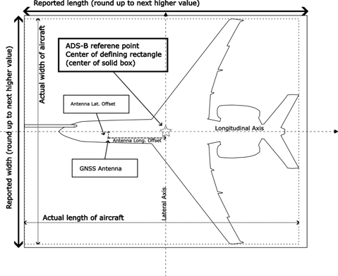
Figure 2 - A/C length, width and antenna offset
- (iii) ADS-B Emitter Category - Set emitter category per manufacturer instructions. Table 6 provides guidance on setting the emitter category that is appropriate for the type of aircraft it is being install on.
|
Emitter Category |
Description |
|---|---|
|
No Emitter Category |
Do not use this emitter category. If no emitter category fits your installation, seek guidance from Transport Canada as appropriate. |
|
Light Aeroplane < 15,500 lbs |
Any Aeroplane with a maximum takeoff weight less than 15,500 pounds (7,031 kg). This includes very light aeroplanes as defined in 521.01, Division I, Subpart 21, Part 5 of the Canadian Aviation Regulations |
|
Small Aeroplane ≥ 15,500 to < 75,000 lbs |
Any aeroplane with a maximum takeoff weight greater than or equal to 15,500 pounds (7,031 kg) but less than 75,000 pounds (34,019 kg). |
|
Large Aeroplane ≥ 75,000 to |
Any aeroplane with a maximum takeoff weight greater than or equal to 75,000 pounds (34,019 kg) but less than 300,000 pounds (136,078 kg) that does not qualify for the high vortex category. |
|
Large Aeroplane with High Vortex |
Any aeroplane with a maximum takeoff weight greater than or equal to 75,000 pounds (34,019 kg) but less than 300,000 pounds (136,078 kg) that has been determined to generate a high wake vortex. Currently, the Boeing 757 is the only example. |
|
Heavy ≥ 300,000 lbs |
Any aeroplane with a maximum takeoff weight equal to or above 300,000 pounds (136,078 kg). |
|
High Performance > 5g and > 400 TAS |
Any aeroplane, regardless of weight, that can maneuver in excess of 5g’s and maintain true airspeed above 400 knots. |
|
Rotorcraft |
Any rotorcraft, regardless of weight. |
|
Glider / Sailplane |
Any glider or sailplane, regardless of weight. |
|
Lighter Than Air |
Any lighter-than-air (airship or balloon), regardless of weight. |
|
Parachute / Sky Diver |
For use by parachute / sky divers. |
|
Ultra-light Vehicle |
Basic and Advanced Ultra-light Vehicles as defined by Subpart 101, Part 1 of the Canadian Aviation Regulations |
|
RPAS |
Any remotely piloted aircraft or system regardless of weight. |
|
Space/Trans-atmospheric Vehicle |
For use by space/trans-atmospheric vehicles. |
|
No ADS-B Emitter Category Information |
Do not use this emitter category. If no emitter category fits your installation, seek guidance from Transport Canada as appropriate |
|
Surface Vehicle—Emergency Vehicle |
For use by surface emergency vehicles. |
|
Surface Vehicle—Service Vehicle |
For use by surface vehicles. |
|
Point Obstacle (Includes Tethered Balloons) |
For use by point obstacles to include tethered Balloons. |
|
Cluster Obstacle |
For use by cluster obstacles. |
|
Line Obstacle |
For use by line obstacles. |
- (iv) MOPS version number – Set the TSO MOPS level / version number. Version 2 applies to ADS-B equipment that meets MOPS documents RTCA/DO-260B with corrigendum 1 or RTCA/DO-282B with corrigendum 1. ADS-B equipment outputting version 2 or higher is required by section 551.103 of Chapter 551 of the AWM
- (v) System Design Assurance (SDA) – the SDA must be set in accordance with system safety assessment. See 5.1(4), 5.1(15) for more details on how to set this parameter.
5.3 Position Source
(1) Equipment Eligibility - Section 551.103 of Chapter 551 of the AWM is performance based and does not require any specific position source. The existing navigation equipment and airworthiness standards should be used; however, they must address the unique requirements associated with ADS-B. A TSO authorization alone is not sufficient to ensure ADS-B compatibility. Appendix B of this AC has more information on identifying and qualifying suitable position sources. Compliance with Appendix B may be documented in the position source manufacturer’s installation instructions.
Note: Not all GNSS position sources will provide the same availability. Refer to Appendix B for more information on GNSS availability.
The position source should be installed in accordance with the applicable guidance. New GNSS position sources may be installed in accordance with FAA AC 20-138(), Airworthiness Approval of Positioning and Navigation Systems.
(2) Position Source and ADS-B Equipment Interface - Unless the ADS-B equipment manufacturer has analyzed the interface between the position source and the ADS-B equipment you are installing, and specifically listed the position source in the ADS-B equipment’s installation manual, you must provide an analysis of the interface between the position source and the ADS-B equipment that demonstrates the position, velocity, position accuracy, position integrity, and velocity accuracy information taken from the position source is properly interpreted by the ADS-B equipment. When installing modifications to a position source, the applicant must determine and test those portions of the ADS-B system that are impacted by the modification and ensure the ADS-B system is not adversely impacted.
Note: This analysis will require engineering design data from the ADS-B equipment manufacturer and/or the position source manufacturer.
(3) Secondary Position Source - There is no requirement to have a secondary position source input. However, if you interface a secondary position source to the ADS-B system, it must meet the requirements in Appendix B of this AC.
Note: If a position source is unable to provide section 551.103 of Chapter 551 of the AWM accuracy and integrity values, it will not qualify the aircraft to operate in airspace that requires ADS-B as defined by the DAH.
(4) Position Source Selection - If multiple position sources (such as MMR/GPS, IRS/INS/ADIRU or GPS1 & GPS2) are interfaced to the ADS-B equipment, source selection can be accomplished manually by the pilot, automatically by the aircraft’s navigation system, or by the ADS-B equipment. We discourage automatic selection of the ADS-B position source based solely on the navigation source in use because operational requirements sometimes dictate a navigation source that may not provide the best ADS-B performance. If the ADS-B equipment accomplishes the position source selection, it should do so in accordance with TSO-C166b. If multiple sources are interfaced to the ADS-B system, there should be a means for the flight crew to readily determine which source is selected. Describing how this selection is performed in the AFM is one acceptable means of compliance.
Note: TSO-C166b requires the ADS-B equipment to use a single position source at a given time for the latitude, longitude, horizontal velocity, accuracy metrics, and integrity metrics.
(5) Navigation Position Source - The ADS-B position source does not need to be the same position source used for navigation. It is acceptable for a GNSS position source to be embedded in the ADS-B equipment and provide position information to the ADS-B system without providing any navigation information to other onboard systems. As addressed in Appendix B of this AC, an integrated GNSS position source should still meet the requirements of TSO-C145(), TSO-C146(), or TSO-C196().
(6) Configuration of Associated Parameters - This section provides additional guidance on setting key ADS-B Out parameters. Definitions for each of the following associated parameters are included in Appendix A.
- (a) Latitude and Longitude - The ADS-B equipment must set the latitude and longitude based on the real-time position information provided by the position source.
- (b) Horizontal Velocity - The ADS-B equipment must set the horizontal velocity based on the real-time velocity information provided by the position source. The ADS-B equipment must transmit a north/south and an east/west velocity while airborne, and a combination of ground speed and ground track or heading while on the surface. Ensure the position source provides horizontal velocity in both formats or ensure the ADS-B equipment can properly convert between formats. We recommend transmitting heading instead of ground track while on the surface. Refer to section 5.5(3) of this AC for additional information on interfacing heading.
- (c) Surface Horizontal Position – The ADS-B equipment must set the surface latitude and longitude based on the real-time position information provided by the position source. This parameter is transmitted while on the ground and is activated via the air/ground logic.
- (d) Source Integrity Level (SIL) - SIL is typically a static (unchanging) value and may be set at the time of installation if a single type of position source is integrated with the ADS-B system. SIL is based solely on the position source’s probability of exceeding the reported integrity value and should be set based on design data from the position source equipment manufacturer. Installations that derive SIL from GNSS position sources that are compliant with any revision of TSO-C129, TSO-C145, TSO-C146, or TSO-C196 and output Horizontal Protection Level (HPL) or Horizontal Integrity Level (HIL) should set the SIL = 3 because HPL and HIL are based on a probability of 1x10⁻⁷ per-hour. Do not base NIC or SIL on Horizontal Uncertainty Level (HUL) information. If integrating with a noncompliant GPS, SIL must be set to “0”.
- (e) Source Integrity Level Supplement (SILSUPP) - SILSUPP is based on whether the position source probability of exceeding the reported integrity value is calculated on a per-hour or per-sample basis and should be set based on design data from the position source equipment manufacturer. ADS-B systems interfaced with a GNSS position source compliant with any revision of TSO-C129, TSO-C145, TSO-C146, or TSO-C196 may pre-set SILSUPP to “ZERO,” as GNSS position sources use a per-hour basis for integrity.
- (f) Navigation Integrity Category (NIC) - The ADS-B equipment must set the NIC based on the real-time integrity metric provided by the position source. When interfacing GNSS position sources, the NIC should be based on the HPL or HIL. However, although HPL values significantly smaller than 0.1 nautical mile (nm) can be output from single-frequency GNSS sources, the HPL may not actually achieve the reported level of protection as there are error contributions that are no longer considered negligible. You should review the position source design data to determine if all error sources are taken into consideration, or if the position source limits the HPL output, when computing an unaugmented Receiver Autonomous Integrity Monitoring (RAIM) based HPL. This applies to all TSO-C129() and TSO-C196() position sources, and to TSO-C145() and TSO-C146() position sources when operating in unaugmented modes where the HPL is based on RAIM. This may apply to some position sources even when operating in an augmented mode. If the position source does not account for all errors or accomplish the appropriate HPL limiting, you must ensure you interface the position source to ADS-B equipment that limits the NIC ≤ 8. Refer to section Appendix B, of this AC for additional information regarding HPL considerations.
- (g) Navigation Accuracy Category for Position (NACp) - The ADS-B equipment must set the NACp based on the real-time 95-percent accuracy metric provided by the position source. When interfacing GNSS sources, the NACp should be based on a qualified Horizontal Figure of Merit (HFOM).
- (h) Navigation Accuracy Category for Velocity (NACV) - Set the NACV based on design data provided by the position source manufacturer. The NACV may be updated dynamically from the position source or set statically based on qualification of the position source.
- A NACV = 1 (< 10 m/s) may be permanently set at installation for GNSS equipment passing the tests identified in Appendix B of this AC, or may be set dynamically from velocity accuracy output of a position source qualified in accordance with the guidance in Appendix B.
- A NACV = 2 (< 3 m/s) must be set dynamically from velocity accuracy output of a position source qualified in accordance with the Appendix B guidance. Do not permanently pre-set a NACV = 2 at installation, even if the position source has passed the tests identified in Appendix B.
- A NACV = 3 or NACV = 4 should not be set based on GNSS velocity accuracy unless you can demonstrate to the Minister that the velocity accuracy actually meets the requirement.
- (i) Geometric Altitude - Ensure the geometric altitude provided by the position source is based on Height-Above-Ellipsoid (HAE) instead of Height-Above-Geoid (HAG). Do not interface a position source that provides HAG or Mean Sea Level (MSL) altitude to the ADS-B equipment unless the ADS-B equipment has the ability to determine the difference between an HAG and HAE input, and the ADS-B equipment has demonstrated during design approval that it can properly convert HAG to HAE using the same model as the position source. It would also be acceptable to demonstrate that the error due to conversion of HAG to HAE does not cause the Geometric Vertical Accuracy to be exceeded.
- (j) Geometric Vertical Accuracy (GVA) – optional parameter – If available, set the GVA based on design data provided by the position source manufacturer. GNSS position sources may provide the geometric altitude accuracy through the Vertical Figure of Merit (VFOM). If the position source does not output a qualified vertical accuracy metric, the GVA parameter should be set to “0”.
- (k) Ground Track Angle - For installations that do not have heading information available, ground track from the position source must be transmitted while on the surface. Many position sources will provide accurate ground track information, but the ground track may only be accurate above certain ground speeds. If the position source ground track is inaccurate below a certain ground speed and the position source does not inhibit output of the ground track at these slower speeds, the applicant should ensure the ADS-B equipment has the capability to invalidate the ground track when the GNSS ground speed falls below 7 knots. Erroneous ground track readings could be misleading for ATC surface operations and ADS-B IN applications. If the position source itself inhibits output of ground track at slower speeds where the ground track would be inaccurate, the applicant may interface the position source ground track to the ADS-B equipment without any restrictions.
5.4 Barometric Altitude Source
(1) Equipment Eligibility - Use barometric altitude from a barometric altimeter that meets the minimum performance requirements of section 551.103 of Chapter 551 of the AWM. The following are each an acceptable means of compliance:
- (a) TSO-C10, Altimeter, Pressure Actuated, Sensitive Type (any revision)
- (b) TSO-C106, Air Data Computer (any revision)
- (c) Ensure the equipment was tested and calibrated to transmit altitude data corresponding within 125 feet (on a 95-percent probability basis) of the indicated or calibrated datum of the altimeter normally used to maintain flight altitude, with that altimeter referenced to 29.92 inches of mercury / 1013.2 mbar for altitudes from sea level to the maximum operating altitude of the aircraft.
Note: If appropriate, use a digitizer meeting the minimum performance requirements of any revision of TSO-C88, Automatic Pressure Altitude Reporting Code-Generating Equipment.
(2) Installation Guidance - The barometric altitude used for the ADS-B broadcast must be from the same altitude source as the barometric altitude used for the ATC transponder Mode C reply, if an altitude-encoding transponder is installed in the aircraft.
(3) Section 551.103 of Chapter 551 of the AWM does not alter any existing regulatory guidance regarding the barometric altitude accuracy or resolution. For example, if an operation requires a 25-foot altitude resolution or a CAR 604.56 (RVSM Requirements) accuracy, that resolution and accuracy should be reflected in the ADS-B message.
(4) If a secondary altitude source is used when a secondary transponder is selected or a secondary altitude source is selected for a single transponder, the altitude source for ADS-B must also be changed so the altitude source remains the same for both the transponder and ADS-B system.
(5) Configuration of Associated Parameters - This section provides additional guidance on setting key ADS-B Out parameters. Definitions for each of the following associated parameters are included in Appendix A:
- (a) Barometric Altitude - The ADS-B equipment must update the barometric altitude based on the real-time barometric altitude provided by the barometric altitude source.
- (b) Barometric Altitude Integrity Code (NICBARO) – optional parameter – If available, you should verify the type of altitude source installed in the aircraft and interface the altitude system per the ADS-B equipment manufacturer’s instructions. For aircraft with an approved, non-Gillham altitude source, NICBARO should be pre-set at installation to “ONE”. For aircraft with a Gillham altitude source without an automatic cross-check, NICBARO must be pre-set at installation to “ZERO”. For aircraft that dynamically cross-check a Gillham altitude source with a second altitude source, the NICBARO must be set based on the result of this cross-check. We recommend that ADS-B installations use non-Gillham altitude encoders to reduce the potential for altitude errors.
- (c) Selected Altitude – if available, this parameter must send the selected altitude shown to the flight crew on the flight management system / master control panel / flight control unit / autoflight system guidance panel, or other system guiding the aircraft vertically, as appropriate.
- (d) Barometric Pressure Setting – if available, this parameter must send the barometric pressure setting selected by the flight crew, minus 80 000 Pascals;
5.5 Heading Source
(1) Equipment Eligibility - For installations that integrate heading on the airport surface, the heading source must meet the minimum performance requirements of any revision of TSO-C5, Direction Instrument, Non-Magnetic (Gyroscopically Stabilized), or any revision of TSO-C6, Direction Instrument, Magnetic (Gyroscopically Stabilized). The equipment must have the appropriate installation and airworthiness approval.
(2) Installation Guidance - The heading does not need to come from the same source as the position and velocity. Interfacing heading is not required but is highly encouraged if the aircraft has an approved heading source.
(3) Configuration of Associated Parameters - When the aircraft is on the surface, the ADS-B system is required to transmit either heading or ground track; however, we recommend transmitting heading if a source of heading information is available and valid. True heading is preferred, but magnetic heading is acceptable. Ensure the heading type (true or magnetic) interfaced to the ADS-B equipment matches the heading type transmitted from the ADS-B equipment.
5.6 TCAS Source
(1) Equipment Eligibility - TCAS II systems should comply with TSO-C119a, Traffic Alert and Collision Avoidance System (TCAS) Airborne Equipment, TCAS II, or subsequent version, and be installed in accordance with FAA AC 20-131A, Airworthiness Approval of Traffic Alert and Collision Avoidance Systems (TCAS II) and Mode S Transponders, or any revision of FAA AC 20-151, Airworthiness Approval of Traffic Alert and Collision Avoidance Systems (TCAS II), Versions 7.0 and 7.1 and Associated Mode S Transponders, as applicable. No ADS-B interface is available or required for TCAS I systems.
Note: Many aircraft will be equipped with a Mode S transponder with ADS-B functionality and a TCAS II. The Mode S transponder is considered to be a component of the TCAS II system and also a component of the ADS-B system.
(2) Installation Guidance
- (a) TCAS II Interface - TCAS II is not a required part of the ADS-B system; however, if TCAS II is installed on your aircraft, the equipment must be integrated so the “TCAS installed and operational” and the “TCAS traffic status” parameters indicate the real-time status of the TCAS II.
- (b) TCAS II Hybrid Surveillance - If an ADS-B IN system is installed in an aircraft equipped with a TCAS II hybrid surveillance system compliant with RTCA/DO-300(), Minimum Operational Performance Standards (MOPS) for Traffic Alert and Collision Avoidance System II (TCAS II) Hybrid Surveillance, the TCAS II will use ADS-B IN position data to reduce the interrogation rates of low-threat intruders. The information transmitted by ADS-B Out systems installed in accordance with the guidance in this AC is suitable for use by TCAS II hybrid surveillance. Refer to FAA AC 20-151() for more information on hybrid surveillance.
- (c) TCAS Messages - The ADS-B transmission of the “TCAS operational” or “TCAS Resolution Advisory (RA) active” messages does not increase the hazard level of the ADS-B equipment defined in TSO-C166b.
(3) Configuration of Associated Parameters - This section provides additional guidance on setting key ADS-B Out parameters. Definitions for each of the following associated parameters are included in Appendix A of this AC.
- (a) TCAS Installed and Operational - This parameter must interface with the TCAS II system if a TCAS II system is installed on your aircraft. This parameter should be pre-set to “ZERO” if a TCAS II is not installed in your aircraft or if a TCAS I is installed in your aircraft. Typically, this parameter will already be provided to the Mode S transponder from the TCAS II. TCAS II systems compliant with TSO-C119() indicate they are operational and able to issue an RA when they transmit Reply Information (RI) = 3 or 4 to the transponder.
- (b) TCAS Traffic Status - This parameter must be interfaced with the TCAS II system if a TCAS II system is installed on your aircraft. The TCAS traffic status parameter can be pre-set to “ZERO” in accordance with the ADS-B equipment manufacturer’s instructions if a TCAS II is not installed.
5.7 Pilot interface
(1) Installation Guidance
- (a) System Status - The installation must have a method to display system operational status to the flight crew and should be consistent with the overall flightdeck design philosophy. The system must display flight crew inputs such as Mode 3/A code, emergency codes, IDENT, and call sign. If an existing transponder is used to input Mode 3/A codes, emergency codes, and IDENT into the ADS-B system, the current transponder control interface is sufficient. The following two failure annunciations must be included in the initial airworthiness certification (that is, STC or TC) type design data for the ADS-B Out equipment and should be consistent with the overall flightdeck design philosophy for surveillance equipment. These failure conditions are advisory only and do not constitute a caution or warning condition.
- (i) ADS-B Device Failure - if the ADS-B equipment is unable to transmit ADS-B messages, the system should provide an appropriate annunciation to the flight crew.
- (ii) ADS-B Function Failure - The ADS-B system depends on a position source to provide the data to populate the ADS-B messages and reports. If the position source or its interface with the ADS-B equipment fails, the ADS-B system will not be able to broadcast the required ADS-B data. In this case, the ADS-B equipment has not failed, but it cannot perform its function due to a failure to receive the position source data. The ADS-B system should distinguish between a position source or interface failure and an ADS-B equipment failure. The applicant must provide documentation, in the applicable flight manual, or flight manual supplement, that explains how to differentiate between annunciation of an equipment failure and a function failure if the failure annunciations are not independent. The ADS-B function failure must not cause a TCAS II system failure.
- Note: Certain advanced ADS-B IN applications may require flight crew knowledge of own-ship ADS-B Out operational status. Refer to AC 20-172() for guidance regarding ADS-B IN installations.
- (b) Turning Off ADS-B - CAR 605.35 requires that all aircraft equipped with transponder and automatic pressure altitude reporting equipment to operate with the equipment turned on at all times. In addition, section 551.103 of Chapter 551 of the AWM includes ADS-B Out as such equipment. However, ATC may request ADS-B turned OFF on for some specific ground operations. When ADS-B functionality resides in the Mode S transponder, it is acceptable to disable the ADS-B transmissions by disabling the transponder (that is, “Standby” or “Off”). If this architecture is used, specify the impact in the flight manual or pilot’s guide (for example, loss of ADS-B, transponder, and TCAS functionality). Locate the ADS-B on/off controls to prevent inadvertent actuation.
(2) Configuration of Associated Parameters - This section provides additional guidance on setting key ADS-B Out parameters. Definitions for each of the following associated parameters are included in Appendix A of this AC.
- (a) Call Sign/Flight ID - The assigned aircraft registration mark must be set as the call sign/flight ID during installation. Procedures for dynamically selecting a call sign must be included in the flight manual or pilot’s guide if the ADS-B equipment provides a means to input a radio telephony call sign. If pilot-selectable, the call sign/flight ID should be readily apparent to the flight crew. When the aircraft system is powered on, the call sign/flight ID must be filled. At initial power-on it is acceptable for the call sign/flight ID to revert to a previously set call sign that existed before the system being powered off, or to the aircraft registration mark.
- Note: The pre-set call sign/flight ID will have to be updated if the aircraft’s registration number changes.
- (b) Emergency Status - The installation must provide a means for the pilot to enter the emergency status of the aircraft. Although TSO-C166b identifies multiple emergency codes, only the codes for general emergency, no communications, and unlawful interference are required to be available for broadcast. It is acceptable to base the ADS-B emergency status on the emergency status code input into the transponder (that is, Mode 3/A codes 7500, 7600, and 7700). Refer to section 5.7(2)(e) of this AC for information on single point of entry of the emergency status.
- (c) IDENT - The installation must provide a means for the pilot to enter the IDENT feature. Refer to section 5.7(2)(e) of this AC for information on single point of entry of the IDENT.
- (d) Mode 3/A Code - The installation must provide a means for the pilot to enter the Mode 3/A code. Refer to section 5.7(2)(e) of this AC for information on single point of entry of the Mode 3/A code.
- (e) Single Point of Entry - Aircraft equipped with a separate transponder and ADS-B system should provide the pilot a single point of entry into both systems for the Mode 3/A code, IDENT, and emergency status. If ADS-B equipment sets the emergency status, IDENT, or Mode 3/A code based on entry of these parameters into a separate transponder, the STC/TC needs to identify the appropriate transponder interfaces. Operator mitigations alone to prevent differing codes from being entered in the transponder and ADS-B system are not acceptable. Additionally, there are workload and safety concerns of requiring the pilot to enter the Mode 3/A code, IDENT, and emergency codes multiple times. Thus, if you do not provide a single point of entry for the mode 3/A code, IDENT, and emergency code, you must accomplish a human factors evaluation and an additional system safety assessment as follows:
- (i) Human Factors Evaluation. Installations not providing a single point of entry must accomplish an evaluation of the pilot interface controls to ensure the design minimizes the potential for entry errors by the flight crew and enables the flight crew to detect and correct errors that do occur. Evaluate the system interface design to ensure dual entry of the emergency status, IDENT, and Mode 3/A code does not introduce significant additional workload, particularly when communicating an aircraft emergency. Refer to section 6.2(12) of this AC for additional information on human factors evaluation.
- (ii) System Safety Assessment. Transmission of false or misleading information is considered to be a major failure effect and may not occur at a rate greater than 1x10⁻⁵ per flight hour for ADS-B systems. Installations not providing a single point of entry must accomplish a safety assessment that demonstrates that the probability of the transponder and ADS-B system ever transmitting differing Mode 3/A codes is less than 1x10⁻⁵ per flight hour. The analysis must consider the potential of all pilot errors.
5.8 ADS-B Antenna Interface
(1) Antenna Location and Number Required - The aircraft ADS-B antenna system is a fundamental part of the overall ADS-B Out architecture because antenna systems (includes cables and connectors) are major contributors to the system link performance. The location and number of antennas required for the airborne ADS-B Out system is a function of the constraints for each installation, where signal path blockage, correct orientation, structural strength, and other parameters must be considered to design an antenna system that results in an acceptable minimum transmit pattern gain in both top and bottom hemispheres of the aircraft.
(2) Typically, for aircraft of metallic construction, a system with antenna diversity will be the simplest configuration with such capabilities. In this case, the system will have two antennas, one mounted on the top and another one on the bottom of the aircraft, providing unrestricted view for transmissions going to satellite and ground based receivers. However, some aircraft constructed with materials that are transparent to Radio Frequency (RF) in the 1090ES frequency band, might be able to use a system that can demonstrate an acceptable transmit pattern gain in both top and bottom hemispheres of the aircraft, with a single antenna. In this case, the location for the antenna needs to be determined carefully after considering the aircraft particular constraints and be verified by test.
(3) Equipment Eligibility - ADS-B antennas must meet requirements defined in the ADS-B equipment manufacturer’s installation manual.
(4) Installation Guidance
- (a) Using an Existing Antenna - When using an existing antenna system, if the installation does not modify the existing antenna(s), cabling, connectors or output specifications, the antenna installation does not have to be revaluated.
- Note: the existing antenna system must be capable of transmitting with, at least, the Effective Radiated Power (ERP) defined in DO-260B section 3.3.4.6 to both top and bottom hemispheres.
- (b) Installing a New Shared Transponder/ADS-B Antenna - To verify the transponder capabilities, follow the transponder antenna installation guidance in AC 20-151().
- (c) Structural Analysis - You may need to submit a structural analysis of new antenna installation to show compliance with the applicable regulations.
- (d) Single Antenna - Single antenna installations must be able to transmit to space-based and ground-based receivers. Section 6 of this AC has more details.
- (e) Mutual Suppression - Follow the ADS-B equipment manufacturer’s guidance on interfacing the ADS-B Out equipment to the mutual suppression bus.
(5) Configuration of Associated Parameters - This section provides additional guidance on setting key ADS-B Out parameters. Definitions for each of the following associated parameters are included in Appendix A to this AC
- (a) GNSS Antenna Offset and Position Offset Applied (POA) – optional parameter – If available, the GNSS antenna offset and position offset applied parameter needs to be set accordingly, if transmitted. The ADS-B position reference point is the center of the rectangle used to describe the length and width of the aircraft in the length and width code. Refer to Figure 2 of this AC. For a more detailed description of POA, refer to RTCA/DO-338, Minimum Aviation System Performance Standards (MASPS) for ADS-B Traffic Surveillance Systems and Applications (ATSSA), section 3.2.4.1.
- If the ADS-B equipment is interfaced to multiple GNSS position sources that use GNSS antennas in different locations on the aircraft and this optional parameter is transmitted, the installation must have provisions to ensure the appropriate GNSS antenna offset is being transmitted when the ADS-B equipment switches from one position source to another.
- The POA setting of the GNSS antenna indicates if the broadcast position of the vehicle is referenced to either a) the aircraft’s ADS-B position reference point, or b) the lateral distance from centerline and longitudinal distance from the most forward part of the aircraft.
- Note: Either the transmitted position should be adjusted to the reference point described above in this paragraph OR the GNSS antenna offsets should be provided. It is not required to do both.
- (b) Single Antenna Bit – optional parameter – If available, the 1090 ES data protocol includes a bit to indicate, at any time, if only one or both antennas (if installed) are functional and should be set to the appropriate value. For aircraft using a single antenna, this parameter should be set to one, “True”.
5.9 Vertical Rate Source
(1) We recommend that the ADS-B system output the optional vertical rate field when available. The vertical rate may come from a barometric air data computer, a GNSS source, or a system that filters barometric and geometric vertical rates. Vertical rate will typically come from a position source or an air-data computer. This section addresses this unique parameter.
(2) Equipment Eligibility - Unlike position accuracy, vertical velocity accuracy is not transmitted in ADS-B messages. Thus, it is important that vertical velocity sources integrated into the ADS-B system meet minimum performance requirements at installation. Use the following guidance:
- (a) Hybrid Vertical Rate Source - Vertical rate may be taken from a hybrid system that filters barometric vertical rate with an Inertial Reference Unit (IRU) vertical rate and GNSS vertical rate, provided the hybrid system was tested and approved to provide a vertical rate output with an accuracy that is at least as good as barometric vertical rate sources (such as TSO-C106). Hybrid vertical rate could come from a Flight Management System (FMS), Air Data and Inertial Reference System (ADIRS), or IRU. ADS-B equipment should transmit hybrid vertical rate solutions as barometric vertical rates.
- (b) Blended Vertical Rate Source - Vertical rate may be taken from a blended system that filters IRU vertical rate and barometric vertical rate, provided the blended system was tested and approved to provide a vertical rate output with an accuracy that is at least as good as barometric vertical rate sources (such as TSO-C106). Blended vertical rate could come from an FMS, ADIRS, or IRU. ADS-B equipment should transmit blended vertical rate solutions as barometric vertical rates.
- (c) Barometric Vertical Rate Source - Barometric vertical rate may be taken from an air data computer meeting the minimum performance requirements of any revision of TSO-C106 or a vertical velocity instrument meeting the minimum performance requirements of applicable revisions of TSO-C8, Vertical Velocity Instruments (Rate-of-Climb). We recommend you use any revision of a TSO-C106 compliant air data computer if you interface barometric vertical rate to the ADS-B Out equipment.
- (d) GNSS Vertical Rate Source - Geometric vertical rate may be taken from any revision of TSO-C129, TSO-C145, TSO-C146, or TSO-C196 GNSS equipment if the position source has been qualified to provide vertical rate in accordance with Appendix B of this AC. Do not interface GNSS vertical velocity if the equipment has not been qualified in accordance with Appendix B.
- (e) Inertial Vertical Rate Source - Vertical velocity from an inertial sensor that is not blended with barometric altitude should not be transmitted from the ADS-B system.
- (f) Barometric Altitude Source - ADS-B systems should not derive a barometric altitude rate by sampling barometric altitude measurements. This could lead to misleading vertical velocity information. If barometric vertical rate is not available, use geometric vertical rate.
(3) Installation Guidance - The vertical rate field can be populated with either barometric vertical rate or geometric vertical rate. There is no requirement to interface multiple vertical velocity sources. We recommend that you use the following priority scheme when selecting or interfacing multiple vertical rate sources:
- (a) Hybrid vertical rate or blended vertical rate.
- (b) Barometric vertical rate.
- (c) INSS vertical rate.
(4) Configuration of Associated Parameters - This section provides additional guidance on setting key ADS-B Out parameters pertaining to vertical rate:
- (a) Vertical Rate – optional parameter – If available, interface vertical rate from one or more of the sources listed in paragraph (2) above. Ensure the source provides vertical rate in feet per minute or ensure the ADS-B equipment can recognize the vertical rate basis and convert the vertical rate to feet per minute.
- (b) Vertical Rate Source – optional parameter – If available, the source bit for vertical rate should be coded as barometric when using barometric rate from an air data computer, or when using a blended or hybrid vertical rate. The source bit for vertical rate should only be coded as geometric when using vertical rate from a GNSS source.
5.10 Air-Ground Considerations
(1) Length and Width Code - The length and width code is required by section 551.103 of Chapter 551 of the AWM, and is only transmitted in the surface position message. Thus, to comply with the rule, the aircraft must automatically determine its air-ground status and transmit the surface position message, which includes the length and width code, when on the ground.
(2) Air-Ground Status - For aircraft with retractable landing gear, the air-ground status determination is typically provided through landing gear weight-on-wheels (WOW) switches. For aircraft that have fixed gear, the ADS-B system must still be able to determine the air-ground status of the aircraft. Installations that provide a means to automatically determine air-ground status based on inputs from other aircraft sensors may be acceptable if they can be demonstrated to accurately detect the status. For example, air-ground status may be derived from WOW switch and GPS velocity; or GPS velocity, an airport database, and geometric altitude; or GPS velocity and airspeed. These algorithms should be tested and validated during the installation approval.
Note 1: We recommend that any automatic air-ground determination be more robust than just a simple comparison of ground speed to a single threshold value. Field experience has shown that this method can lead to false air-ground status.
Note 2: Manual selection of the air-ground status is not acceptable.
Note 3: Rotorcraft may require unique logic for providing an accurate air-ground state. A reliable method to determine the air-ground state should consider training requirements. Rotorcraft may consider hover taxi as in the air.
(3) Mode S Transponder Inhibit - TSO-C112d and TSO-C112e, Air Traffic Control Radar Beacon System/Mode Select (ATCRBS/Mode S) Airborne Equipment, requires Mode S transponders to inhibit the reply to Mode A/C/S all-call and Mode S-only all-call interrogations on the surface. Mode S transponders with ADS-B functionality will now remain “ON” during surface operations; thus it is imperative that you ensure the transponder interface to the air-ground status is installed correctly and that the transponder does not reply to Mode A/C/S all-call or Mode S-only all-call interrogations on the surface.
Note: In deploying Airport Surface Detection Equipment version X (ASDE-X) at various airports, we have found transponder installations that have been improperly wired and therefore inappropriately respond to ATC and TCAS interrogations while on the airport surface.
5.11 Foreign Airspace Requirements
(1) Optional Parameters - If operations are planned in a country that requires parameters not mandated in Canada, such as ADS-B In Capability or Special Position Identification, follow the ADS-B equipment manufacturer’s installation guidance to interface those parameters. Table 23 in Appendix D shows a comparison between TCCA/FAA/EASA required parameters.
6.0 Means of compliance (MoC)
6.1 MoC Overview
(1) For installation approval, subsection 551.103(c)(3) of Chapter 551 of the AWM requires applicants to show equipment compliance to any of A1, A2, A3, B1, A1S or B1S classes of TSO-C166 revision b or later; and subsection 551.103(d)(4) requires applicants to show antenna installations compliance to section 3.3 of RTCA/DO-260B, with an additional requirement for single antenna installations (classes A1S and B1S) that the equipment transmits satisfactorily to ground-based and space-based receivers.
(2) Antenna diversity (classes A1, A2, A3 or B1) installations are preferred over the single antenna (classes A1S and B1S) type. The means of compliance to paragraph 3.3.4.6 “Installed Equipment Antenna System” of RTCA/DO-260B have been well established and available since 2011 and this system architecture choice has been shown to adequately emit towards both -- space-based (SB) and ground-based (GB) receivers. A limited test will be sufficient to demonstrate compliance for this type of installation.
(3) Single antenna installations have predominantly placed the antenna on the bottom of the fuselage, aiming for single (bottom) hemisphere emission towards ground-based receivers or other aircraft flying nearby. See Figure 3 for a diagram of the top and bottom hemispheres.

Figure 3 - Top and Bottom Transmission Hemispheres – Diversity
(4) Bottom-only antenna installations typically will not be able to satisfactorily transmit to SB receivers. The predominant antenna type used in these installations is the ¼ wave matched monopole, which has an emission pattern predominant to the hemisphere above the ground plane. However, other types of antenna installations might achieve adequate performance to both GB and SB receivers, i.e., single dipole antenna with a clear view of both hemispheres, multiple antennas working as an array, etc. For these non-diversity types of installations, demonstration of system performance is the preferred means of compliance. For clarity, see Figure 4 with a diagram of an ideal single antenna installation capable of transmitting to both hemispheres.

Figure 4 - Top and Bottom Transmission Hemispheres – Single Antenna
(5) Table 7 is a summary of the accepted MoC that are described in this Advisory Circular. Details will follow in the subsequent sections.
| Number of Antennas |
2 |
1 |
1 |
1 |
2 or more |
|---|---|---|---|---|---|
|
Diversity? |
Yes |
N/A |
N/A |
N/A |
No |
|
Position |
top and bottom |
top |
bottom |
other |
other |
|
DO-260B Class |
A1, A2, A3, B1 |
A1S, B1S |
A1S, B1S |
A1S, B1S |
N/A |
|
Basic ground test |
Yes (per section 6.2) |
Yes (per section 6.2) |
Yes (per section 6.2) |
Yes (per section 6.2) |
Yes (per section 6.2) |
|
Antenna Perf. ground test |
No |
Yes (per section 6.3) |
Yes (per section 6.3) |
Yes (per section 6.3) |
Yes (per section 6.3) |
|
End-to-end flight test (DAPR) |
Yes (per section 6.4) |
Yes (per section 6.4) |
Yes (per section 6.4) |
Yes (per section 6.4) |
Yes (per section 6.4) |
6.2 Basic Ground Tests
(1) The basic ground tests described in this section should be performed to demonstrate that the system meets its intended function considering each of the interfacing systems and that only correct information is transmitted.
IMPORTANT NOTE: Over-the-air transmissions may interfere with ATC, especially with other ADS-B equipped in-range aircraft. Coordinate with ATC prior to broadcasting during tests and use antenna shielding (that is, transmission absorption covers or caps) to prevent transmission of test data that could generate false intruder information.
(2) System Latency - Latency is addressed through analysis rather than testing. Refer to Appendix C of this AC.
(3) Accuracy and Integrity Performance - Ensure the installed system meets its stated accuracy and integrity performance under expected operating conditions. We recommend that you accomplish a GNSS performance prediction for the applicable time of your test to ensure the ADS-B system meets the predicted performance. In the absence of predicted GNSS performance, demonstrate that you meet all subsection 551.103 (d)(2) of Chapter 551 of the AWM requirements as listed in Table 8.
| Parameter |
Minimum Accuracy and Integrity Performance |
|---|---|
|
NIC ≥ 7 |
Horizontal Containment Radius Limit : |
|
NACp ≥ 8 |
95% Horizontal Accuracy Bound: |
|
NACV ≥ 1 |
Horizontal Velocity Error: |
|
SIL = 3 |
Probability of Exceeding the NIC Containment Radius: |
|
SDA ≥ 2 |
Probability of Undetected Fault causing transmission of False or Misleading Information: |
(4) Parameters – Per subsection 551.103(d)(1) of Chapter 551 of the AWM, ensure the following parameters are properly populated and transmitted:
|
Parameter |
|
|---|---|
|
1 |
International Civil Aviation Organization (ICAO) 24-bit aircraft address; |
|
2 |
Surface horizontal position (latitude and longitude); |
|
3 |
Transponder IDENT when in use; |
|
4 |
Emergency/Priority status; |
|
5 |
Aircraft Identification (Flight identification or aircraft registration number/marking); |
|
6 |
Airborne horizontal position (latitude and longitude); |
|
7 |
Barometric pressure altitude; |
|
8 |
ADS-B emitter category; |
|
9 |
Geometric altitude (GNSS height); |
|
10 |
Horizontal velocity (airborne and on the ground) |
|
11 |
Length and width of aircraft; |
|
12 |
Mode A code; |
|
13 |
Navigation Integrity Category (NIC); |
|
14 |
Navigation Accuracy Category for Position (NACp); |
|
15 |
Navigation Accuracy Category for Velocity (NACV) |
|
16 |
Source Integrity Level (SIL); |
|
17 |
System Design Assurance (SDA); |
|
18 |
MOPS version number; |
|
19 |
TCAS installed and operational; |
|
20 |
TCAS traffic status (if installed); |
|
21 |
Selected altitude (if available in a suitable format); and |
|
22 |
Barometric pressure setting (if available in a suitable format). |
Note: optional or other parameters not listed in Table 9 that are chosen by the applicant to be part of the transmission need to have their correct value transmitted. Otherwise, such parameters should be removed from the transmission. For example, EASA CS ACNS defines the parameter “GNSS antenna offset” as mandatory. If the applicant chooses to include this parameter, its value must match the actual GNSS antenna offset value.
(5) Position Accuracy - Position the aircraft on a surveyed location and validate the position transmitted from the ADS-B system. Ensure the position transmitted is within the allotted NACp accuracy limit. For example, if the aircraft reports a NACp = 8, the ADS-B position should be within 92.6 meters (0.05 nm). If the aircraft reports a NACp = 10, the ADS-B position should be within 10 meters. Refer to Table 14 in Appendix A of this AC for a complete list of NACp values. If the transmitted position accuracy is smaller than or equal to the resolution of the test equipment, it is acceptable to use plus or minus one Least Significant Bit as the pass/fail criteria.
(6) Barometric Altitude Accuracy - Validate that the barometric altitude transmitted from the ADS-B system is accurate to within 125 feet and matches the barometric altitude reported by the transponder.
(7) Electromagnetic Interface (EMI)/Electro Magnetic Compatibility (EMC) Testing - Provide an EMI/EMC test plan that demonstrates compliance with section 523.2510, subsections 525.1353(a) and (b), 525.1431(a) and (c), sections 527.1301, 527.1309, subsections 529.1353(a) and (b), and 529.1431(a) and (b) of the respective AWMs as appropriate. Accomplish EMI/EMC testing to ensure the ADS-B equipment does not provide an interference source on other installed systems on the aircraft. Additionally, ensure equipment already installed in the aircraft does not interfere with the ADS-B system. If the STC or TC only involves a software change to an existing approved Mode S transponder installation, and the software update will not affect the systems response to EMI, you do not need to accomplish EMI testing again.
(8) Human Machine Interface - Evaluate the flight crew interface for the ADS-B Out system, including the human-system interface and system behavior. The ADS-B Out system must be compatible with the overall flightdeck design characteristics (such as access to controls, sunlight readability, night lighting, etc.) as well as the aircraft environment (such as vibrations).
(9) Information Display - Evaluate the ADS-B Out system to ensure displayed information is easily and clearly discernible, and has enough luminance, size, and visual contrast for the pilots to see and interpret it. Ensure the pilots have a clear, unobstructed, and undistorted view of the displayed information elements. Ensure information elements are distinct and permit the pilots to determine the source of the information elements, if necessary, when there are multiple sources of the same kind of information.
(10) Controls and Labelling - Evaluate the controls for the pilot interface to ensure they are plainly marked as to their intended function, provide convenient operation, and prevent confusion and inadvertent operation of both the ADS-B system and the other systems with which they interact. Evaluate the acronyms, labels, and annunciations to ensure they are used consistently in the flightdeck, and do not cause confusion or errors. If a control performs more than one function, evaluate the labels to ensure the labels include all intended functions, unless the function of the control is obvious. During evaluation, consider line select keys, touch screens or cursor-controlled devices (such as trackballs) as these can be susceptible to unintended mode selection resulting from their location in the flight deck (for example, proximity to a footrest or temporary stowage area).
(11) Annunciations and Alerts - Evaluate all ADS-B annunciations and alerts to ensure they are clear and unambiguous and provide attention-getting and saliency appropriate to the type of alert. Compliance with FAA AC 25.1322-1, Flight crew Alerting; FAA AC 27.1322 (in FAA AC 27-1B, Certification of Normal Category Rotorcraft); and FAA AC 29.1322 (in FAA AC 29-2C, Certification of Transport Category Rotorcraft) should be considered when evaluating ADS-B annunciations and alerts. The colours yellow/amber and red should be restricted to cautions and warnings, respectively. Evaluate the annunciations and indications to ensure they are operationally relevant and limited to minimize the adverse effects on flight crew workload. When an annunciation is provided for the status or mode of a system, it is recommended that the annunciation indicate the actual state of the system, and not just the position of a switch. Note that any failure flag presented on the Primary Flight Display (PFD) is to be considered part of the alerting function.
(12) Pilot Interface Errors - Installations not providing a single point of entry for the ADS-B and transponder for the Mode 3/A code, IDENT, and emergency status must accomplish an evaluation of the pilot interface controls to determine that they are designed to minimize entry errors by the flight crew and enable the flight crew to detect and correct errors that do occur. System interface design must also be evaluated to ensure dual entry of the Mode 3/A code, IDENT, and emergency status does not introduce significant additional workload, and that the controls are acceptable for data entry, accuracy, and error rates, particularly when communicating an aircraft emergency. Evaluations should consider pilot-detected and undetected error rates, pilot workload, and training times. Refer to section 6.2 for additional information on transponder and ADS-B system single point of entry.
(13) Lighting - Evaluate all foreseeable conditions relative to lighting, including failure modes such as lighting and power system failure, and day and night operations.
(14) Transponder Regression Testing - At a minimum, use the procedures outlined in FAA AC 43-6(), Altitude Reporting Equipment and Transponder System Maintenance and Inspection Practices, to validate that the transponder is operating normally following the ADS-B installation. Use the procedures outlined in FAA AC 20-151() for ADS-B systems that include installation of a new or modified Mode S transponder. If you are installing a new air-ground status capability for the ADS-B system and this functionality is also interfaced to the transponder, you must ensure replies to the Mode A/C and ATCRBS/Mode S all-call interrogations are inhibited on the ground.
(15) ICAO 24-Bit Address - For Canadian civil aircraft, demonstrate that the 24-bit address transmitted by the ADS-B Out system correlates to the aircraft mark and matches the Mode S transmitted 24-bit address. If the aircraft has a separate UAT ADS-B system installed, ensure both systems transmit the same correct ICAO 24-bit address. For non-Canadian registered aircraft, verify that the ICAO 24-bit address is the address assigned to the aircraft by the responsible State authority.
(16) Self Test - Evaluate the ADS-B self-test features (if provided) and failure mode annunciations to ensure the pilot is able to determine whether the system is functioning properly.
(17) Position Source Failure - Demonstrate that a failure or loss of the position source results in an indication to the operator of an ADS-B function failure. If a secondary position source is interfaced to the ADS-B equipment, ensure it meets all guidance in this AC. If the change from the primary position source to the secondary position source requires a change in SIL or SDA, ensure these changes are accomplished within 12 seconds.
(18) Air-Ground Status - Verify that the air-ground inputs (or algorithms) are functioning properly and that the ADS-B system transmits the appropriate airborne messages or surface messages based on the air-ground status. This can be accomplished with simulated inputs to the appropriate sensors or accomplished in conjunction with the flight test. Rotorcraft may consider hover taxi as in the air.
(19) TCAS/ACAS - If a TCAS II / ACAS II system is installed on the aircraft, ensure the proper messages are transmitted by the ADS-B system when the TCAS/ACAS is on and operating in a mode that can provide RAs. No TCAS/ACAS system regression testing beyond the ground interface testing covered in this section is required.
(20) Transponder All-call Inhibit - Demonstrate that the correct Mode 3/A code and IDENT is transmitted. Do not transmit the 7500, 7600, or 7700 emergency codes over the air during ground or flight testing. If testing emergency codes is desired, contact the local ATC facility and coordinate testing to prevent a nuisance emergency response.
(21) Transmit Power - Transmit power testing must be accomplished if a new antenna has been installed, an existing antenna has been relocated, a diplexer has been installed into an existing antenna system, or the output specifications on the transponder have changed. Perform the following testing to validate transmit power:
- (a) Verify that the peak pulse power at the antenna end of the transmission line meets the minimum and maximum power levels summarized in Table 10, considering the test equipment antenna gain and path loss.
- Note: Upgrading a previously installed and approved TSO-C112() Mode S transponder to include ADS-B functionality does not require transmit power testing unless a new antenna has been installed, the antenna location has changed, or the output specifications on the transponder have changed.
|
Tested Transmitter Class |
Minimum Power |
Maximum Power |
|---|---|---|
|
A1 |
21.0 dBW (125 W) |
27.0 dBW (500 W) |
|
A1S |
21.0 dBW (125 W) |
27.0 dBW (500 W) |
|
B1 |
21.0 dBW (125 W) |
27.0 dBW (500 W) |
|
B1S |
21.0 dBW (125 W) |
27.0 dBW (500 W) |
|
A2 |
21.0 dBW (125 W) |
27.0 dBW (500 W) |
|
A3 |
23.0 dBW (200 W) |
27.0 dBW (500 W) |
6.3 Antenna Performance Ground Tests
(1) To minimize compliance demonstration burden on applicants, this AC differentiates between installation types aiming to use as much data as possible from previously approved systems.
(2) As shown in Table 7, the first major distinction is made between applicants seeking approval for the installation of an ADS-B Out system on an aircraft that already has an approved Mode S transponder system per the minimum requirements of TSO-C112(), where this approved transponder transmitter and antenna(s) will be used to broadcast the ADS-B Out messages.
(3) For aircraft that do not have an approved Mode S transponder installation and are seeking for concurrent approval with the ADS-B Out system, the applicant can follow guidance in FAA AC 20-151() as an acceptable means of compliance.
(4) The next distinction is made between systems with and without diversity. Subsection 551.103(c)(3) of Chapter 551 of the AWM requires applicants to show equipment compliance to any of A1, A2, A3, B1, A1S or B1S Classes of TSO-C166 b or later revision; Subsection 551.103(d)(4) requires applicants to show antenna installations compliance to section 3.3 of RTCA/DO-260B, with the added requirement that for single antenna installations (Classes A1S and B1S), it can be demonstrated that the equipment transmits satisfactorily to ground-based and space-based receivers.
(5) Systems with antenna diversity are preferable because the transmissions occur alternately, with full transmitter power, to the top and bottom antennas, maintaining the long-range capabilities and enabling the ADS-B messages to reach ground-based and satellite-based receivers. Systems with antenna diversity will not be required to demonstrate antenna performance through the tests described in this section 6.3.
(6) Systems with a single antenna, or antenna arrays without diversity, will need to show radiated power equivalency to that of a system with diversity. The following definition of minimum acceptable transmit gain is quoted (with slight editing) from DO-260B paragraph 2.2.13.1:
“The gain of an omni-directional transmit antenna is not less than the gain of a matched quarter-wave stub minus 3 dB over 90 percent of the coverage volume from 0 to 360 degrees in azimuth and from 5 to 30 degrees above the ground plane, when installed at the center of a 1.2 m diameter (or larger) flat circular ground plane.”
(7) These criteria will be applied to the bottom and top hemispheres around the aircraft, as if two quarter-wave stub antennas were mounted in a mirrored configuration. For single, dipole antenna installations, the reference plane for both hemispheres will be the horizontal plane located at the middle of the antenna. See Figure 4 . For antenna array installations without diversity, the reference planes will be similar to a system with diversity. See Figure 3.
(8) The minimum acceptable antenna gain, when coupled with the minimum acceptable power at the antenna terminal per the transmitter classes of DO-260B, define the minimum effective radiated power (ERP) for the installed system.
(9) To determine the ERP for the installed system, follow procedure described in paragraph 3.3.4.6.1 of DO-260B, except that for measurements on the bottom hemisphere, there is no need to raise the aircraft if the measurement point is below the ground. It will be sufficient to measure at the ground level. See Figure 5.
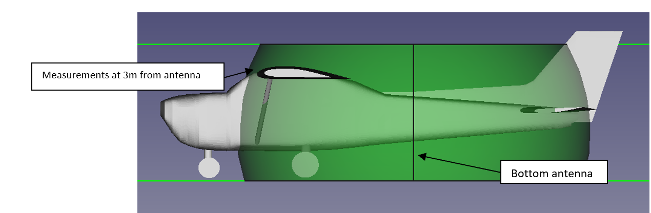
Figure 5 - ERP measurement planes
(10) The aircraft should be as far as possible from metallic constructions to minimize the effect of reflections. A compass-swing wind rose would be the ideal location.
(11) You must coordinate with ATC before performing any over-the-air transmissions.
(12) Follow steps 1 through 10 from paragraph 3.3.4.6.1 Verification of Transmit Pattern Gain of DO-260B. As explained, if on steps 8, 9 or 10 the measuring point results below the ground, it is sufficient to measure at the ground level and measurements at steeper elevation angles for the bottom hemisphere will not be necessary. The pass/fail criteria is given at each step of the procedure.
6.4 End-to-End Flight Test
(1) This section provides information on flight testing ADS-B systems to verify that the NAV CANADA system properly receives the aircraft’s ADS-B broadcast messages, dropouts are within maximum acceptable statistical values, and the information transmitted is complete and correct. Currently the only method available to accomplish the flight test is to fly within SB ADS-B service coverage and accomplish a post-flight analysis of the data received from NAV CANADA.
Note 1: This flight test is intended to complete a design approval under an STC or TC application;
Note 2: Follow your standard process for requesting flight test authorization; there are no unique flight test authorization requirements for ADS-B flight tests.
(2) Electromagnetic Interference - During all phases of flight, survey the flight deck EMI to determine that the ADS-B Out equipment is not a source of objectionable conducted or radiated interference to previously installed systems or equipment, and that operation of the ADS-B Out equipment is not adversely affected by conducted or radiated interference from previously installed systems and equipment.
(3) Other System Performance - Demonstrate the proper performance of any previously installed aircraft systems which required changes as a result of the ADS-B installation. This can be accomplished with standard regression test procedures for the affected, previously installed systems.
(4) User Interface - Exercise all user inputs. If separate user inputs are required for the transponder and ADS-B systems, evaluate the flight manual procedures for ensuring the same Mode 3/A code, IDENT, and emergency codes are transmitted from both systems.
(5) Location/Time of Flight and System Status - The best flight test results will be obtained by choosing a location and time for nominal performance of both GNSS and the SB ADS-B system.
There will be time periods when non-augmented GNSS solutions do not provide the required performance for NIC and NACp. Space-based system outages or underperformance, due to scheduled maintenance or other ad-hoc conditions like solar windstorms will directly influence flight test results. It is therefore recommended that you accomplish a GNSS performance prediction for the applicable time of your test, prior to flight testing.
From an SB ADS-B system perspective, flight test results will also be directly influenced by traffic density. ADS-B receivers must recognize and decode ADS-B messages in the presence of other 1090 MHz transmissions including those of collision avoidance systems and transponder radar replies. This is particularly challenging for SB ADS-B receivers, as their antenna patterns pick up 1090 MHz transmissions from a relatively large area. A single satellite is able to receive signals from a large swath of land (more than 1,000 x 1,000 km) In certain geographic areas, congestion due the large number of transmissions from all services adversely impacts SB ADS-B performance. In this case, the number of valid messages that are properly received and decoded by the SB system might be lower than nominal and there might be insufficient data to declare adequate system functionality. In this case, a subsequent flight test might be requested. Flight tests executed in lower traffic density conditions, whether due to time of day or area, will be less subject to this issue [see also paragraph 6.4(12)].As a guideline only, at the time of this writing, NAV CANADA has included a high level map which depicts areas that experience 1090 MHz congestion in the Public ADS-B Performance Report (PAPR) User Guide posted on their website at the following link: https://www.navcanada.ca/en/papr-user-guide.pdf. Applicants may choose to perform their flight test outside of that area or seek guidance from NAV CANADA on the optimal location and time of test flight.
Note: While signals from ADS-B Out equipment located anywhere on earth can be received by space receivers, the flight should take place within Canadian domestic airspace in order for the data to be analyzed by NAV CANADA per this AC as described in paragraph (12).
(6) Flight Test Profile - This profile is intended to be flown on all ADS-B system approvals. The profile need not be flown exactly, and variances for ATC clearances and vectors are acceptable. The flight test should be at least 1 hour long. Because the pass/fail criteria is based on statistics, longer flight durations will benefit from more data received. The profile discussed below may be flown in any order.
(7) Altitude - Fly the aircraft at multiple altitudes throughout the flight within ADS-B coverage. There is no maximum or minimum altitude required for the flight test.
(8) Turns - Verify the ADS-B system performs properly during turning maneuvers. During the flight, place the aircraft in various normal configurations such as takeoff, approach, landing, and cruise configuration if appropriate for the airframe. During the flight, perform at least two left and two right 360-degree turns. Table 11 below provides the suggested altitude, speed, and bank angle at which these turns should be made. The intent of this test is to ensure the ADS-B system operates properly over the normal flight regimes of the aircraft under test. Variations on altitude, speed, and bank angle are acceptable as long as the intent of the test is met.
|
AWM 523 Aircraft |
||
|---|---|---|
|
Configuration |
Speed Range |
Bank Angle |
|
Takeoff |
1.4 VS |
30° |
|
Approach or Landing |
1.4 VS |
30° |
|
Cruise |
1.5 VS to 1.8 VS |
30° |
|
AWM 525 Aircraft |
||
|
Configuration |
Speed Range |
Bank Angle |
|
Takeoff |
V2 + 20 kts |
30° |
|
Approach or Landing |
VAPP + 20 kts |
30° |
|
Cruise |
1.5 VS to 1.8 VS |
30° |
|
AWM 527 Rotorcraft |
||
|
Configuration |
Speed Range |
Bank Angle |
|
Landing |
VY + 10 kts |
30° |
|
Cruise |
0.8 VNE or 0.8 VH |
30° |
|
AWM 529 Rotorcraft |
||
|
Configuration |
Speed Range |
Bank Angle |
|
Landing |
VY + 10 kts |
30° |
|
Cruise |
0.8 VNE or 0.8 VH |
30° |
(9) Climbs/Descents - Verify the ADS-B system performs properly during climbs and descents. Table 12 provides a suggested airspeed for climbs during the test flight. Table 13 provides a suggested airspeed for descents during the test flight. Climbs and descents should be at least one minute in length. The intent of this test is to ensure the ADS-B system operates properly over the flight regime of the aircraft under test. Variations in climb and descent rates are acceptable as long as the intent of the test is met.
|
Configuration |
Part 23 Aircraft |
Part 25 Aircraft |
Part 27 Rotorcraft |
Part 29 Rotorcraft |
|---|---|---|---|---|
|
Take off |
VY |
VFE - 10 kts |
VY |
VY |
|
Cruise |
VH |
VMO - 10 kts |
0.8 VNE or 0.8 VH |
0.8 VNE or 0.8 VH |
|
Configuration |
Part 23 Aircraft |
Part 25 Aircraft |
Part 27 Rotorcraft |
Part 29 Rotorcraft |
|---|---|---|---|---|
|
Cruise |
VNE - 10 kts |
VMO - 10 kts |
0.8 VNE or 0.8 VH |
0.8 VNE or 0.8 VH |
|
Approach |
VFE - 10 kts |
VFE - 10 kts |
VY + 10 kts |
VY + 10 kts |
|
Landing |
VFE - 10 kts |
VFE - 10 kts |
N/A |
N/A |
(10) Post-flight Data Analysis - You must accomplish a post-flight data analysis to ensure the aircraft is transmitting ADS-B information accurately. Request a Detailed ADS-B Performance Report (DAPR) from NAV CANADA and ensure the available data associated with the track is consistent, such as 24-bit address, aircraft registration, emitter category, flight ID, barometric altitude, Mode 3A, SIL, SDA, NIC and NACp. Request by email to: service@navcanada.ca, with the following email subject: Request for Detailed ADS-B Performance Report
(11) The post-flight data analysis should also reveal if there were any unexpected data dropouts that might be caused by intermittent wiring interfaces or interface incompatibility. This can be verified through the probability of update (PU) with an update interval of 8s value provided on the DAPR report from NAV CANADA. The target minimum PU is 96%.
(12) The PU value is calculated from a statistical model and thus, longer flights will transmit more data points, allowing for more robust results. In addition, flying in an area where SB ADS-B reception is impacted by 1090 MHz congestion [see paragraph (5)] might result in PU values lower than the target minimum specified in paragraph (11) even for a compliant installation. In such cases,, you might request a comparison of PU performance between the aircraft under test and other aircraft with approved ADS-B installations flying in its vicinity, which might allow to differentiate between congestion effects and potential installation problems. This analysis will be carried out by NAV CANADA and a summary pass/fail will be provided to the applicant.
Note: a test flight conducted outside of high traffic density areas and/or time (e.g. at night) is ideal to minimize these effects and avoid dependence on the comparative analysis [i.e. meet directly the quantitative PU pass criterion stated in paragraph (11)]. Please refer to recommendations in paragraph 5. However, should that option not be practical, the comparative analysis made by NAV CANADA is offered as a way to alleviate these effects and offer more flexibility in the choice of test flight location and time.
6.5 Subsequent Data Reuse
(1) The guidelines of this AC apply to initial TC/STC applications. Test (ground/flight) data from a similar installation, covered under a previous TC/STC, may be used instead of a new test if the following conditions can be confirmed through the documentation of the previous STC:
- (a) Position Source Equipment - The position source must be identical to that of the other Amended Type Certificate (ATC), TC, or STC documentation. Equipment families that use the same baseline design may build a case by similarity analysis.
- (b) ADS-B Equipment - The ADS-B equipment must be identical to that of the other ATC/TC/STC documentation. Equipment families that use the same baseline design may build a case by similarity analysis.
- (c) System Interface - A direct interface must be used between the position source and the ADS-B equipment, and that interface must be identical to that of the previous ATC/TC/STC. Aircraft with data concentrators will have to re-accomplish the test, even if the equipment is identical.
- (d) Air-Data Interface - The air-data interface to the ADS-B equipment must be identical to that of the previous ATC/TC/STC. The actual air-data source may be different equipment; only the interface to the ADS-B equipment needs to be identical. However, if the air-data source is different, more extensive ground testing should be accomplished, to include a dynamic test where the air-data source has simulated inputs from sea level to the maximum certified operating altitude of the aircraft. Care should be taken to ensure broadcast of simulated altitude information does not cause interference with ATC or ADS-B IN applications.
- (e) Heading Interface - The heading interface to the ADS-B equipment (if applicable) must be identical to that of the previous ATC/TC/STC. The heading source may be different; only the interface to the ADS-B equipment needs to be identical. If the heading source is different, testing should be accomplished, to include positioning the aircraft at multiple headings on the surface to verify heading accuracy.
- (f) TCAS Interface - The TCAS interface to the ADS-B equipment must be identical to that of the previous ATC/TC/STC. The TCAS equipment may be different; only the interface to the ADS-B equipment needs to be identical.
7.0 Document history
(1) AC 500-029, Issue 01, RDIMS 16965437 v5 (E), 17649431 v5 (F), dated 2022-04-22 - Certification of Automatic Dependent Surveillance – Broadcast (ADS-B)
(2) AC 500-029, Issue 02, RDIMS 19649186 v11 (E), 19872945 v9 (F), dated 2024-01-04 - Certification of Automatic Dependent Surveillance – Broadcast (ADS-B)
8.0 Contact us
(1) It is recommended that applicants for an aircraft modification communicate with their TCCA Regional Aircraft Certification office to determine the acceptability and completeness of the proposed tests prior to conducting the flight test. Regional Engineers and Delegates will communicate with TCCA Flight Test to confirm the need to conduct a flight test assessment of the modified aircraft; early notification is recommended.
For more information, please contact:
Aircraft Certification Standards (AARTC)
E-mail: tc.aartcdaircraftdesignstandards-normesdeconceptiondesaeronefsaartcd.tc@tc.gc.ca
(2) We invite you to provide us with your suggestions for amendment to this document. Submit your comments to:
AART Documentation Services
E-mail: AARTDocServices-ServicesdocAART@tc.gc.ca
Original signed by Bernard Champagne for:
Jamie-Lee MacDermid
Executive Director, Standards branch
Civil Aviation
Transport Canada
Appendix A — Message Element Descriptions
1.0 Purpose
(1) This appendix provides a description of the message elements that may be contained in an ADS-B Out message.
2.0 Message Elements
(1) Airspeed - Optionally, true airspeed or indicated airspeed may be transmitted. The airspeed source should be approved to output airspeed data. An air data computer meeting the minimum performance requirements of TSO-C106 is one acceptable source. Do not interface an airspeed source to the ADS-B that has not been approved for cockpit display.
(2) Barometric Pressure Altitude. This parameter indicates the aircraft’s barometric pressure altitude referenced to standard sea level pressure of 29.92 inches of mercury or 1013.2 hectopascals. The barometric pressure altitude is required to be transmitted by section 551.103 of Chapter 551 of the AWM.
(3) Call Sign/Flight ID. The term “aircraft call sign” is the radiotelephony call sign assigned to an aircraft for voice communications purposes. (This term is sometimes used interchangeably with “flight identification” or “flight ID”). For general aviation aircraft, the aircraft call sign is normally the national registration number; for airline and commuter aircraft, the call sign is usually comprised of the company identification and flight number (and therefore not linked to a particular airframe) and, for the military, it usually consists of numbers and code words with special significance for the operation conducted. The call sign or aircraft registration number is required to be transmitted by section 551.103 of Chapter 551 of the AWM.
(4) Emergency Status. This parameter alerts ATC that the aircraft is experiencing emergency conditions and indicates the type of emergency. Applicable emergency codes are found in ICAO Annex 10 Volume 4, Surveillance Radar and Collision Avoidance Systems. This information alerts ATC to potential danger to the aircraft so it can take appropriate action. Emergency status is required to be transmitted by section 551.103 of Chapter 551 of the AWM.
(5) Emitter Category. The emitter category provides an indication of the aircraft’s size and performance capabilities. Emitter categories are defined in TSO-C166b. Emitter category is designed primarily to provide information on the wake turbulence that an aircraft produces. Emitter category is required to be transmitted by section 551.103 of Chapter 551 of the AWM.
(6) Geometric Altitude. The geometric altitude is a measure of altitude provided by a satellite-based position service and is not affected by atmospheric pressure. Geometric altitude is only available with a GNSS position source. Geometric altitude for ADS-B purposes is the height above the World Geodetic System 1984 (WGS-84) ellipsoid (HAE). Geometric altitude is required to be transmitted by section 551.103 of Chapter 551 of the AWM.
(7) Geometric Vertical Accuracy (GVA). The GVA indicates the 95-percent accuracy of the reported vertical position (geometric altitude) within an associated allowance.
(8) GNSS Antenna Offset and Position Offset Applied (POA) - The GNSS antenna offset indicates the longitudinal distance between the most forward part of the aircraft and the GNSS antenna, and the lateral distance between the longitudinal center line of the aircraft and the GNSS antenna. Also, refer to section 5.8(4) and Figure 2 of this AC.
(9) The POA setting of the GNSS antenna offset indicates that the broadcast position is referenced to the aircraft’s ADS-B position reference point versus the GNSS antenna location. Also, refer to section 5.8(4) and Figure 2 of this AC. of this AC. For further details about POA, refer to RTCA/DO-338, section 3.2.4.1
(10) Ground Speed. This parameter is also derived from the position sensor and provides ATC with the aircraft’s speed over the ground. This parameter is reported in the surface position message.
(11) Ground Track Angle. The ground track angle is the direction of the horizontal velocity vector over the ground. Ground track or heading is required to be transmitted while on the ground to transmit complete velocity information.
(12) Heading. Heading indicates the direction in which the nose of the aircraft is pointing. There is no heading accuracy metric. Heading or ground track is required to be transmitted while on the ground to transmit complete velocity information.
(13) Horizontal Velocity. The horizontal velocity provides the rate at which an aircraft changes its horizontal position with a clearly stated direction. Horizontal velocity is provided with the north/south velocity and the east/west velocity parameters while airborne. Horizontal velocity is provided by a combination of the ground speed and heading or ground track while on the surface. TSO-C166b requires that the north/south velocity, east/west velocity, ground speed, and ground track come from the same source as the position. Heading information may come from a separate source. Horizontal velocity is required to be transmitted by section 551.103 of Chapter 551 of the AWM.
(14) ICAO 24-bit Address. The ICAO 24-bit address is a unique address assigned to an aircraft during the registration process. ICAO 24-bit addresses are defined blocks of addresses assigned for participating countries or states worldwide. In the Canada, civil aircraft are assigned an address from an encoding scheme based on the aircraft marks. Additional information regarding the 24-bit address can be found in ICAO Annex 10, Part I, Volume III, appendix to Chapter 9, A World-Wide Scheme for the Allocation, Assignment and Application of Aircraft Addresses. The ICAO 24-bit address is required to be transmitted by section 551.103 of Chapter 551 of the AWM.
(15) IDENT is a flag manually set by the pilot at the request of ATC in ATCRBS, Mode S, and ADS-B messages. The pilot manually enables the IDENT state, which highlights their aircraft on the controller’s screen. IDENT is required to be transmitted by section 551.103 of Chapter 551 of the AWM.
(16) Latitude and Longitude. These parameters are derived from the position source and provide a geometric based position. Reference all geometric position elements broadcast from the ADS-B unit to the WGS-84 ellipsoid. Latitude and longitude are required to be transmitted by section 551.103 of Chapter 551 of the AWM.
(17) Length and Width of Aircraft. This parameter provides ATC and other aircraft with quick reference to the aircraft’s dimensions while on the surface. Aircraft length and width is required to be transmitted by section 551.103 of Chapter 551 of the AWM.
(18) Mode 3/A Code. Currently ATC automation relies on the Mode 3/A code to identify aircraft under radar surveillance and correlate the target to a flight plan. The mode 3/A code is a four-digit number ranging from 0000 to 7777. Secondary Surveillance Radars (SSR) and ADS-B will concurrently provide surveillance, so the Mode 3/A code is included in the ADS-B Out message and is required to be transmitted by section 551.103 of Chapter 551 of the AWM. Note: ADS-B systems will not transmit the Mode 3/A code if the Mode 3/A code is set to 1000.
(19) Navigation Accuracy Category for Position (NACp). The NACp specifies the accuracy of the aircraft’s horizontal position information (latitude and longitude) transmitted from the aircraft’s avionics. The ADS-B equipment derives a NACp value from the position source’s accuracy output, such as the HFOM from the GNSS. The NACp specifies with 95 percent probability that the reported information is correct within an associated allowance. Section 551.103 of Chapter 551 of the AWM specifies a minimum NACp value of “8” must be transmitted to operate in ADS-B airspace . Table 14 provides the applicable NACp values:
|
NACp value |
Horizontal Accuracy Bound |
|---|---|
|
0 |
EPU ≥ 18.52 km (10nm) |
|
1 |
EPU < 18.52 km (10nm) |
|
2 |
EPU < 7.408 km (4nm) |
|
3 |
EPU < 3.704 km (2nm) |
|
4 |
EPU < 1852 m (1nm) |
|
5 |
EPU < 926 m (0.5nm) |
|
6 |
EPU < 555.6 m (0.3nm) |
|
7 |
EPU < 185.2 m (0.1nm) |
|
8 |
EPU < 92.6 m (0.05nm) |
|
9 |
EPU < 30 m |
|
10 |
EPU < 10 m |
|
11 |
EPU < 3 m |
(20) Navigation Accuracy Category for Velocity (NACV The NACV is an estimate of the accuracy of the horizontal geometric velocity output. The coding of “0” indicating that the accuracy is unknown or either equal to or worse than 10 meters per second (m/s), is of little value to ADS-B applications. There is no vertical rate accuracy metric. A NACV of greater than or equal to “1” is required by section 551.103 of Chapter 551 of the AWM. Table 15 provides the applicable NACV values.
|
NACV value |
Velocity Accuracy Bound |
|---|---|
|
0 |
≥ 10 m/s |
|
1 |
<10 m/s |
|
2 |
<3 m/s |
|
3 |
<1 m/s |
|
4 |
<0.3 m/s |
(21) Navigation Integrity Category (NIC). The NIC parameter specifies a position integrity containment radius. NIC is reported so surveillance applications, such as ATC or other aircraft, may determine whether the reported geometric position has an acceptable level of integrity for the intended use. The NIC parameter is closely associated with the SIL. While NIC specifies the integrity containment radius, SIL specifies the probability of the actual position lying outside that containment radius without indication. ADS-B systems should derive the NIC from an approved position source’s integrity output, such as the HPL from the GNSS. A minimum NIC value of “7” must be transmitted to operate in airspace defined in section 551.103 of Chapter 551 of the AWM. Table 16 provides the applicable NIC values.
|
NIC |
Radius of Containment |
|---|---|
|
0 |
Unknown |
|
1 |
RC < 37.04 km (20.0 nm) |
|
2 |
RC < 14.816 km ( 8.0 nm) |
|
3 |
RC < 7.408 km ( 4.0 nm) |
|
4 |
RC < 3.704 km ( 2.0 nm) |
|
5 |
RC < 1.852 km ( 1.0 nm) |
|
6 Sup A=1 Sup B=1 |
RC < 1.111 km ( 0.6 nm) |
|
6 Sup A=0 Sup B=0 |
RC < 926 m ( 0.5 nm) |
|
6 Sup A=0 Sup B=1 |
RC < 555.6 m ( 0.3 nm) |
|
7 |
RC 370.4 m ( 0.2 nm) |
|
8 |
RC < 185.2 m ( 0.1 nm) |
|
9 |
RC < 75 m |
|
10 |
RC < 25 m |
|
11 |
RC < 7.5 m |
(22) NICBARO. Indicates if pressure altitude is provided by a single Gillham encoder or another more robust altitude source. Because of the potential for an undetected error in a Gillham encoding, many Gillham installations are cross-checked against a second annotates the status of this cross-check.
(23) Position. These parameters are derived from the position source and provide a geometric based position. Reference all geometric position elements broadcast from the ADS-B unit to the WGS-84 ellipsoid. Latitude and longitude is required to be transmitted by section 551.103 of Chapter 551 of the AWM.
(24) Single Antenna Bit. This parameter indicates if the ADS-B equipment is transmitting through a single antenna.
(25) Source Integrity Level (SIL). The SIL field defines the probability of the reported horizontal position exceeding the radius of containment defined by the NIC, without alerting, assuming no avionics faults. Although the SIL assumes there are no unannunciated faults in the avionics system, the SIL must consider the effects of a faulted Signal-In-Space (SIS), if a SIS is used by the position source. A SIL value of “3” must be transmitted to operate in airspace defined in section 551.103 of Chapter 551 of the AWM.Table 17 outlines the SIL values.
Note 1: The probability of an avionics fault causing the reported horizontal position to exceed the radius of containment defined by the NIC, without alerting, is covered by the SDA parameter.
Note 2: The SIL probability can be defined as either per sample or per-hour as defined in the SIL supplement (SILSUPP ).
|
SIL Value |
Probability of exceeding the NIC containment radius |
|---|---|
|
0 |
> 1x10⁻³ per-hour or Sample or Unknown |
|
1 |
≤ 1x10⁻³ per-hour or Sample |
|
2 |
≤ 1x10⁻⁵ per-hour or Sample |
|
3 |
≤ 1x10⁻⁷ per-hour or Sample |
(26) Source Integrity Level Supplement (SILSUPP). The SILSUPP defines whether the reported SIL probability is based on a per-hour probability or a per-sample probability as defined in Table 18.
|
SIL Supplement |
Basis for SIL Probabilitycontainment radius |
|---|---|
|
0 |
Probability of exceeding NIC containment radius is based on per-hour. |
|
1 |
Probability of exceeding NIC containment radius is based on per-sample. |
(27) System Design Assurance (SDA). The SDA parameter defines the failure condition that the ADS-B system is designed to support as defined in Table 18. The supported failure condition will indicate the probability of an ADS-B system malfunction causing false or misleading position information or position quality metrics to be transmitted. This should include the probability of exceeding the containment radius without annunciation. Because the applicant does not know how the broadcast data from the ADS-B Out equipment will be used, the applicant cannot complete a Functional Hazard Assessment (FHA) evaluating the use of the broadcast data. The SDA provides a surrogate for such a FHA by identifying the potential impact of an erroneous position report caused by an equipment malfunction. The definitions and probabilities associated with the supported failure effect are defined in AC 25.1309-1, AC 23.1309-1(),and AC 29-2 (Changes 1-3 incorporated). The SDA includes the position source, ADS-B equipment, and any intermediary devices that process the position data. section 551.103 of Chapter 551 of the AWM requires an SDA of 2 or 3 as defined in Table 19.
|
SDA Value |
Supported Failure Condition Note 2 |
Probability of Failure Causing Transmission of False or Misleading Information Note 3,4 |
Software & Hardware Design Assurance Level Note 1,3 |
|---|---|---|---|
|
0 |
Unknown/ No safety effect |
> 1x10⁻³ Per-hour or Unknown |
N/A |
|
1 |
Minor |
≤ 1x10⁻³ Per-hour |
D |
|
2 |
Major |
≤ 1x10⁻⁵ Per-hour |
C |
|
3 |
Hazardous |
≤ 1x10⁻⁷ Per-hour |
B |
Note 1: Software design assurance pursuant to RTCA/DO-178C, Software Considerations in Airborne Systems and Equipment Certification, or equivalent. Airborne electronic hardware design assurance pursuant to RTCA/DO-254, Design Assurance Guidance for Airborne Electronic Hardware, or equivalent.
Note 2: Supported failure classification defined in AC 25.1309-1(), AC 23.1309-1(), and AC 29-2().
Note 3: Because the broadcast position can be used by any ADS-B IN equipped aircraft or by ATC, the provisions in AC 23.1309-1() that allow reduction in failure probabilities and design assurance level for aircraft under 6,000 pounds do not apply for the ADS-B Out system.
Note 4: Includes probability of transmitting false or misleading latitude, longitude, or associated position accuracy and integrity metrics.
(28) TCAS Installed and Operational. This parameter indicates whether the aircraft is fitted with a TCAS II and if the TCAS II is turned on and operating in a mode that can generate resolution advisory alerts. The TCAS installed and operational parameter is required to be transmitted by section 551.103 of Chapter 551 of the AWM.
(29) TCAS Traffic Status. This parameter indicates if a TCAS II equipped aircraft is currently generating a TCAS resolution advisory. The TCAS traffic status parameter is required to be transmitted by section 551.103 of Chapter 551 of the AWM if the aircraft is TCAS II equipped.
(30) Vertical Rate. The vertical rate is the barometric or geometric rate at which the aircraft is climbing or descending, measured in feet per minute. The vertical rate is typically generated by an air data computer or GNSS position source, or equipment that blends barometric vertical rate with inertial vertical rate and/or GNSS vertical rate.
(31) Version Number. The applicable TSO Minimum Operational Performance Standard (MOPS) level is communicated through the version number, which is fixed at the time the ADS-B equipment is manufactured. Version 2 applies to ADS-B equipment that meets MOPS documents RTCA/DO-260B with corrigendum 1 or RTCA/DO-282B with corrigendum 1. ADS-B equipment outputting version 2 or higher is required by section 551.103 of Chapter 551 of the AWM.
Appendix B — Identifying and Qualifying ADS-B Position Sources
1.0 Purpose
(1) This appendix defines the minimum requirements for position sources interfaced to ADS-B systems. The appendix also defines appropriate position source qualification methods when the existing GNSS TSOs do not contain specific requirements or test procedures. The position source manufacturer should provide design data where appropriate, preferably in the GNSS equipment installation manual, so the applicant can properly interface the position source to the ADS-B system. Position source suppliers must ensure any supplied data is incorporated into the article design, and changes to any documented characteristics result in a change to the part number.
2.0 Organization
(1) This appendix includes general guidance that applies to all position sources, as well as GNSS-specific guidance. The appendix also provides high-level requirements for tightly-coupled GNSS/IRU position sources and non-GNSS position sources. Unless otherwise specified, all references in this AC to TSO-C129, TSO-C145, TSO-C146, and TSO-C196 refer to any revision of the TSO.
3.0 General Guidance for All Position Sources
(1) Position. The position source must provide a latitude and longitude output. Requirements and test procedures in TSO-C129/145/146/196 are sufficient and GNSS equipment with Technical Standard Order Authorization (TSOA) for the aforementioned TSOs require no additional qualification for the position output.
(2) Horizontal Velocity. The position source must output north/south and east/west velocities. We recommend the position source also output the velocity in a ground speed and track angle format.
(3) Position Accuracy (Vertical). The position source should output a vertical position accuracy metric. The vertical position accuracy metric must have been qualified during the system’s TSOA or design approval. This output must describe the vertical position accuracy with 95 percent probability under fault-free conditions
(4) Position Accuracy (Horizontal). The position source must have a horizontal position accuracy output, and the output must have been qualified during the system’s TSOA or design approval. This output must describe the radius of a circle in the horizontal plane, with its center being at the true position that describes the region assured to contain the indicated horizontal position with at least 95 percent probability under fault-free conditions.
(5) Position Integrity (Horizontal). The position source must have a horizontal position integrity output qualified during the system’s TSOA or design approval. This integrity output should describe the radius of a circle in the horizontal plane, with its center being at the true position that describes the region assured to contain the indicated horizontal position with at least 99.99999 percent probability under fault-free avionics conditions. Position sources that degrade from a 99.99999 percent probability to a 99.999 percent probability (such as a tightly-coupled inertial/GNSS system after the loss of GNSS) can still be installed; however, they will not meet section 551.103 of Chapter 551 of the AWM following the degradation. In this case, the position source must have a way of indicating the change to the ADS-B equipment. Additionally, if the change of probability is due to a change in position source, the new position source must meet all of the requirements in this appendix
- (a) Mode. If interpretation of the integrity output of the position source can change due to a change in the position source mode, the position source must have a way of communicating that change of mode to the ADS-B equipment. Additionally, the position source manufacturer should provide a description of the modes and a description of how the position source outputs the mode indication
- (b) Validity Limit. If the integrity value of the output cannot be trusted beyond a certain limit, indicate this limitation in the design documentation
- (c) Integrity Fault. The position source must be able to identify, and output, an indication of an integrity fault. This indication should occur within 8 seconds of output of an erroneous position. The position source manufacturer must provide information on how this integrity fault is output
(6) Position Integrity (Probability). The position source manufacturer must provide information describing the basis for the probability of exceeding the horizontal integrity containment radius. This basis must indicate the probability of exceeding the integrity containment radius as well as the sampling duration (per-hour or per-sample)
(7) SIS Error Detection. The position source should provide a means to detect a SIS error when the system uses a SIS. The probability of missed detection for a faulty SIS should be less than 1x10⁻³ GNSS equipment provides the appropriate SIS error detection
(8) Velocity Accuracy. The position source should have a velocity accuracy output that was qualified in conjunction with the system’s TSOA or design approval. Instead of a dynamic output, the position source manufacturer may demonstrate a worst case velocity accuracy that can be assumed based on testing. A test for GNSS position sources is contained in the latest revision of FAA AC 20-138, appendix 4. The position source manufacturer may propose a test method for non-GNSS sources or an alternate test for GNSS sources during the TSOA or design approval.
(9) Design Assurance. The position source must support a major or greater failure effect. This includes software compliant with RTCA/DO-178C, Level C, and airborne electronic hardware (AEH) compliant with RTCA/DO-254, Level C. For airborne electronic hardware determined to be simple, RTCA/DO-254, section 1.6 applies. Because the broadcast position can be used by any ADS-B IN equipped aircraft or by ATC, the provisions in AC 23.1309-1() that allow reduction in failure probabilities and design assurance level for aircraft under 6,000 pounds do not apply for the ADS-B Out system. The overall probability of a position source malfunction causing a position to be output that exceeds the output integrity radius must be less than 1x10⁻⁵ per flight hour.
(10) Geometric Altitude. The position source must have a geometric altitude output. The geometric altitude must be referenced to the WGS-84 ellipsoid
(11) Update Rate. The position source must output a new position at least once per second. Faster position update rates reduce latency of the transmitted position and are encouraged.
(12) Position Source Latency. The position source manufacturer must provide position source latency information. Specifically, the manufacturer must provide the amount of position source total latency and uncompensated latency. Because the latency requirements are based on the entire ADS-B Out system, and not just the position source, the following position source latency targets are only guidelines. Position source uncompensated latency should be less than 200 ms, compensated latency should be less than 500 ms, and total latency should be less than 700 ms.
Note 1: System latency is further described in Appendix C of this AC.
Note 2: This section addresses position latency only
(13) Position, Velocity, and Accuracy Time of Applicability. For each position output by the source, a velocity, horizontal position accuracy metric, and horizontal velocity accuracy metric must also be output. All measurements and metrics must have the same time of applicability. A horizontal position integrity metric must also be output, but its time of applicability may lag the position. Refer to TSO-C145, TSO-C146, or TSO-C196 for additional information on the integrity time to alert.
(14) Time Mark. Position sources should output a time mark identifying the Coordinated Universal Time (UTC) time of applicability of the position. The time mark can be used by the ADS-B equipment to reduce uncompensated latency
(15) Availability. Section 551.103 of Chapter 551 of the AWM does not define an availability requirement; however, it is a significant operational factor when selecting the position source (refer to Table 21).
4.0 GNSS Position Sources
(1) Position - GNSS position sources must provide a latitude and longitude output. Requirements and test procedures in TSO-C129/145/146/196 are sufficient and GNSS equipment with TSOA for the aforementioned TSOs require no additional qualification for the position output. Some GNSS position outputs are referenced to the center of navigation of the aircraft. Manufacturers should document under what conditions the position is output in this manner. Installers must configure the ADS-B installation to account for any position offset from the surveillance reference point or GNSS antenna position as applicable.
Note: The intent is to output position, velocity, and HFOM in a consistent manner for time of applicability (refer to RTCA/DO-229D, Minimum Operational Performance Standards for Global Positioning System/Wide Area Augmentation System Airborne Equipment, sections 2.1.2.6 and 2.1.2.6.2).
- (a) TSO-C129. The requirements outlined for 2D accuracy in section (a)(3)(xvi) of TSO-C129 do not ensure full compliance for the GNSS unit. Additional means of compliance for this TSO require GNSS manufacturers to substantiate that the latitude/longitude is output and referenced to WGS-84 coordinate system.
- (b) TSO-C129a. The requirements outlined for 2D accuracy in section (a)(3)(xvi) of TSO-C129a do not ensure full compliance for the GNSS unit. Additional means of compliance for this TSO require GNSS manufacturers to substantiate that the latitude/longitude is output and referenced to WGS-84 coordinate system.
- (c) TSO-C145/146 Rev a Class 1. Means of compliance for this TSO are defined in RTCA/DO-229C, section 2.1.2.6.
- (d) TSO-C145/146 Rev a Class 2/3. Means of compliance for this TSO are defined in RTCA/DO-229C, sections 2.1.4.8 and 2.1.5.8.
- (e) TSO-C145/146 Rev b/c/d Class 1. Means of compliance for this TSO are defined in RTCA/DO-229D, section 2.1.2.6.
- (f) TSO-C145/146 Rev b/c/d Class 2/3. Means of compliance for this TSO are defined in RTCA/DO-229D, sections 2.1.4.8 and 2.1.5.8.
- (g) TSO-C196/196a. Means of compliance for this TSO are defined in RTCA/DO-316, Minimum Operational Performance Standards for Global Positioning System/Aircraft Based Augmentation System, section 2.1.2.6.
(2) Position Source Latency. GNSS position source manufacturers must provide position source latency information.
- (a) TSO-C129. Means of compliance for this TSO require GNSS manufacturers to document the position source latency from time of measurement (TOM) to time of position output. If this latency exceeds 0.9 seconds, it may not support the 2-second ADS-B transmission latency at the aircraft level.
- (b) TSO-C129a. Means of compliance for this TSO require GNSS manufacturers to document the position source latency from TOM to time of position output. If this latency exceeds 0.9 seconds, it may not support the 2-second ADS-B transmission latency at the aircraft level.
- (c) TSO-C145/146 Rev a Class 1. Means of compliance for this TSO are defined in RTCA/DO-229C, section 2.1.2.6.2
- (d) TSO-C145/146 Rev a Class 2/3. Means of compliance for this TSO are defined in RTCA/DO-229C, sections 2.1.2.6.2 and 2.1.5.8.2
- (e) TSO-C145/146 Rev b/c/d Class 1 Means of compliance for this TSO are defined in RTCA/DO-229D, section 2.1.2.6.2.
- (f) TSO-C145/146 Rev b/c/d Class 2/3. Means of compliance for this TSO are defined in RTCA/DO-229D, sections 2.1.2.6.2 and 2.1.5.8.2
- (g) TSO-C196/196a. Means of compliance for this TSO are defined in RTCA/DO-316, section 2.1.2.6.2.
(3) Availability
- (a) Analysis has shown the following estimated availability for TSO GPS receivers using a 2-degree antenna mask angle (refer to Table 21) assuming the minimum threshold GPS satellite constellation. The Minimum Threshold Constellation is the probability of slots filled with healthy satellites. For Table 20, the FAA and TCCA use the modified interagency forum on operational requirements (IFOR) constellation probabilities that provides a conservative estimate of predicted GNSS availability. The modified IFOR probabilities are not guaranteed by the U.S. Air Force (GPS constellation operator), but are intended to be consistent with the Global Positioning System Standard Positioning Service Performance Standard, revision 4, dated September 2008. Modified IFOR threshold constellation state probabilities based on this performance standard (a 0.99999-percent probability of 20 healthy satellites or satellite pairs in expanded slot configuration) are shown in Table 20.
|
Number of Healthy Satellites |
Probability That Exactly a Given Number of Satellites Are Healthy |
Probability That at Least a Given Number of Satellites Are Healthy |
|---|---|---|
|
24 |
0.72% |
0.72% |
|
23 |
0.17% |
0.89% |
|
22 |
0.06% |
0.95% |
|
21 |
0.03% |
0.98% |
|
20 |
0.02% |
1.00% |
|
19 |
0.00% |
1.00% |
|
18 |
0.00% |
1.00% |
|
Positioning Service (Receiver Standard) |
Predicted Availability (ADS-B Compliance) |
|---|---|
|
GPS (TSO-C129) (SA On) |
≥ 89.0% |
|
GPS (TSO-C196) (SA Off) |
≥ 99.0% |
|
GPS/SBAS (TSO-C145/TSO-C146) |
≥ 99.9% |
- (a) TSO-C129. The requirements outlined for Class A, B, and C equipment provide horizontal integrity through RAIM algorithms under RTCA/DO-208 change 1, Minimum Operational Performance Standards for Airborne Supplemental Navigation Equipment Using Global Positioning System (GPS), section 2.2.1.13. However, there is no requirement to compute or output HPL. To properly comply with the ADS-B requirements, additional means of compliance for this TSO require GNSS manufacturers to provide substantiation data showing that the equipment outputs a 1x10⁻⁷ /hr HPL based on the RAIM algorithm at least once per second that meets a 10-second time to alert. Although section 551.103 of Chapter 551 of the AWM defines 12 seconds as maximum, this AC recommends an 8-second time to alert. The protection level value is acceptable as an HPL if the equipment performs the test in RTCA/DO-208 change 1, section 2.5.2.5 using this protection level value for comparison against the alarm limit. Equipment using the least-squares residual RAIM method recommended in RTCA/DO-208 change 1, appendix F provides an acceptable HPL.
- (b) TSO-C129a. The requirements outlined for Class A, B, and C equipment provide horizontal integrity through RAIM algorithms under RTCA/DO-208 change 1, section 2.2.1.13. However, there is no requirement to compute or output HPL. To properly comply with the ADS-B requirements, additional means of compliance for this TSO require GNSS manufacturers to provide substantiation data showing that the equipment outputs a /hr HPL based on the RAIM algorithm at least once per second that meets a 10-second time to alert. Although section 551.103 of Chapter 551 of the AWM defines 12 seconds as maximum, this AC recommends an 8-second time to alert. The protection level value is acceptable as an HPL if the equipment performs the test in RTCA/DO-208 change 1, section 2.5.2.5 using this protection level value for comparison against the alarm limit. Equipment using the least-squares residual RAIM method recommended in RTCA/DO-208 change 1, appendix F provides an acceptable HPL.
- (c) TSO-C145/146 Rev a Class 1. Means of compliance for this TSO are defined in RTCA/DO-229C, sections 2.1.2.6, 2.1.2.2.2, and 2.1.3.2.2. A summary of the latter requirements can be found in RTCA/DO-229C, section 2.1.1.13.1.
- (d) TSO-C145/146 Rev a Class 2/3. Means of compliance for this TSO are defined in RTCA/DO-229C sections 2.1.2.6, 2.1.2.2.2, 2.1.3.2.2, 2.1.4.2.2, and 2.1.5.2.2. A summary of the latter requirements can be found in RTCA/DO-229C, section 2.1.1.13.1.
- (e) TSO-C145/146 Rev b/c/d Class 1. Means of compliance for this TSO are defined in RTCA/DO-229D, sections 2.1.2.6, 2.1.2.2.2, and 2.1.3.2.2. Related requirements can be found in RTCA/DO-229D, sections 2.1.1.4 and 2.1.4.9.
- (f) TSO-C145/146 Rev b/c/d Class 2/3. Means of compliance for this TSO are defined in RTCA/DO-229D, sections 2.1.2.6, 2.1.2.2.2, 2.1.3.2.2, 2.1.4.2.2, and 2.1.5.2.2. Related requirements can be found in RTCA/DO-229D, sections 2.1.1.4 and 2.1.4.9.
- (g) TSO-C196/196a. Means of compliance for this TSO are defined in RTCA/DO-316, sections 2.1.2.6, 2.1.2.2.2, and 2.1.3.2.
(5) Position Integrity (Probability). GNSS position source manufacturers must provide information describing the basis for the probability of exceeding the horizontal integrity containment radius.
- (a) TSO-C129. Means of compliance for TSO-C129 are defined in RTCA/DO-208 change 1, section 2.2.1.13.1, referring to table 2-1.
- (b) TSO-C129a. Means of compliance for TSO-C129a are defined in RTCA/DO-208 change 1, section 2.2.1.13.1, referring to table 2-1.
- (c) TSO-C145/146 Rev a Class 1. Means of compliance for this TSO are defined in RTCA/DO-229C, section 2.1.2.2.2.1 for Satellite-Based Augmentation System (SBAS) based integrity. This requirement references appendix J, section J.2.1, only). For additional guidance on an acceptable scaling method, GNSS manufacturers can refer to RTCA/DO-229C, appendix U, section 4. FDE requirements can be found in section 2.1.2.2.2.2.2.
- (d) TSO-C145/146 Rev a Class 2/3. Means of compliance for this TSO are defined in RTCA/DO-229C, section 2.1.2.2.2.1 for SBAS-based integrity. This requirement references appendix J, section J.2.1, defining position integrity. (Integrity probability only). For additional guidance on an acceptable scaling method, GNSS manufacturers can refer to RTCA/DO-229C, appendix U, section 4. FDE requirements can be found in section 2.1.2.2.2.2.2.
- (e) TSO-C145/146 Rev b/c/d Class 1. Means of compliance for this TSO are defined in RTCA/DO-229D, section 2.1.2.2.2.1 for SBAS-based integrity. This requirement references to appendix J, section J.3.1, defining position integrity. (Integrity only). For additional guidance on an acceptable scaling method, GNSS manufacturers can refer to RTCA/DO-229D appendix U, section 4. FDE requirements can be found in section 2.1.2.2.2.2.2.
- (f) TSO-C145/146 Rev b/c/d Class 2/3. Means of compliance for this TSO are defined in RTCA/DO-229D, section 2.1.2.2.2.1 for SBAS-based integrity. Appendix J, section J.3.1 provides a background definition for position integrity. (Integrity only). For additional guidance on an acceptable scaling method, GNSS manufacturers can refer to RTCA/DO-229D, appendix U, section 4. FDE requirements can be found in section 2.1.2.2.2.2.2.
- (g) TSO-C196/196a. Means of compliance for this TSO are defined in RTCA/DO-316, section 2.1.2.2.2.2. For additional guidance on an acceptable scaling method, GNSS manufacturers can refer to RTCA/DO-316, appendix U, section 4.
(6) Integrity Fault Alerts. GNSS position source manufacturers must provide design data on the maximum time the position source can take to indicate an integrity fault. If the fault indication is mode specific, data on all modes must be included. It is recommended that the indication of an integrity fault be provided within 8 seconds across all modes. All revisions of TSO-C145, TSO-C146, and TSO-C196 GNSS equipment meet this requirement. No revisions of TSO-C129 GNSS equipment meet this requirement without meeting further qualifications outlined below. Receivers compliant with ARINC Characteristic 743A-5, GNSS Sensor, dated May 2009, represent the condition where a satellite fault has been detected but the receiver was unable to exclude the faulted satellite by setting bit 11 of label 130. This bit must be interpreted to set the position invalid regardless of the indicated HIL or HPL.
- (a) TSO-C129. The requirements in RTCA/DO-208 change 1, section 2.2.1.13.1 cover the time to alarm for different phases of flight. To properly comply with the overall 12-second integrity fault output for ADS-B, additional means of compliance for TSO-C129 require GNSS manufacturers to provide information in the installation instructions describing the equipment integrity fault latency output with interface instructions and/or limitations for meeting the 12-second allocation set by section 551.103 of Chapter 551 of the AWM.
- (b) TSO-C129a. The requirements in RTCA/DO-208 change 1, section 2.2.1.13.1 cover the time to alarm for different phases of flight. To properly comply with the overall 12-second integrity fault output for ADS-B, additional means of compliance for TSO-C129a require GNSS manufacturers to provide information in the installation instructions describing the equipment integrity fault latency output with interface instructions and/or limitations for meeting the 12-second allocation set by this AC.
- (c) TSO-C145/146 Rev a Class 1. Means of compliance for this TSO are defined in RTCA/DO-229C, sections 2.1.1.13 and 2.1.2.2.2.2.1 through 2.1.2.2.2.2.4.
- (d) TSO-C145/146 Rev a Class 2/3. Means of compliance for this TSO are defined in RTCA/DO-229C, sections 2.1.1.13, 2.1.2.2.2.2.1 through 2.1.2.2.2.2.4, and 2.1.4.2.2.2.1 through 2.1.4.2.2.2.3.
- (e) TSO-C145/146 Rev b/c/d Class 1. Means of compliance for this TSO are defined in RTCA/DO-229D, sections 2.1.1.13 and 2.1.2.2.2.2.1 through 2.1.2.2.2.2.4.
- (f) TSO-C145/146 Rev b/c/d Class 2/3. Means of compliance for this TSO are defined in RTCA/DO-229D, sections 2.1.1.13, 2.1.2.2.2.2.1 through 2.1.2.2.2.2.4, and 2.1.4.2.2.2.1 through 2.1.4.2.2.2.3.
- (g) TSO-C196/196a. Means of compliance for this TSO are defined in RTCA/DO-316, sections 2.1.1.11 and 2.1.2.2.2.1 through 2.1.2.2.2.4.
(7) Position Integrity Limits. This requirement was previously called Integrity Validity Limit. Single-frequency RAIM-based HPL computations have been designed to support navigation applications and provide an appropriate error bound down to approximately 0.1 nm. Although HPL values significantly smaller than 0.1 nm can be output from single-frequency GNSS sources, if the HPL value was computed using RAIM, it may not actually achieve the reported level of protection as there are error contributions that are no longer negligible and should be taken into consideration. Such error sources specifically include correlation of ionospheric errors across satellites, tropospheric delay compensation errors, multipath, and receiver noise errors. This issue is not unique to non-augmented GPS position sources, as all revisions of TSO-C145 and TSO-C146 GNSS position sources also calculate integrity based on RAIM when Satellite-Based Augmentation System (SBAS) integrity is not used. Even when using SBAS augmentation, the integrity calculation is not required to account for these error sources except when in LNAV/VNAV or LPV/LP approach modes. ADS-B capable position sources must provide design information to the applicant that identifies the following:
- (a) Whether a TSO-C129 or TSO-C196 position source limits the HPL output to greater than 75 meters. If the position source does not limit its HPL output, the position source manufacturer should provide guidance to the applicant to ensure the ADS-B equipment limits the NIC to ≤ 8. Although single-frequency RAIM-based HPL values are only accurate down to approximately 0.1 nm, for ADS-B purposes, the position source only need limit the HPL to greater than 75 meters, because an HPL greater than 75 meters ensures the ADS-B equipment will only set a NIC of ≤ 8.
- (i) TSO-C129. Means of compliance for this TSO require GNSS manufacturers to present substantiation data whether HPL is limited or not and provide proper installation instructions for the ADS-B integration.
- (ii) TSO-C129a. Means of compliance for this TSO require GNSS manufacturers to present substantiation data whether HPL is limited or not and provide proper installation instructions for the ADS-B integration.
- (iii) TSO-C196/196a. Means of compliance for this TSO require GNSS manufacturers to present substantiation data whether HPL is limited or not and provide proper installation instructions for the ADS-B integration.
- (b) Whether a TSO-C145 or TSO-C146 position source limits the HPL in non-SBAS augmented modes to greater than 75 meters. If the position source does not limit the HPL output in non-augmented modes, the position source manufacturer should provide guidance to the ADS-B system applicant to ensure the ADS-B equipment limits the NIC to ≤ 8 in non-augmented modes. The position source manufacturer should also provide instructions on how to determine the position source mode if appropriate.
- (i) TSO-C145/146 Rev a Class 1. Means of compliance for this TSO require GNSS manufacturers to present substantiation data whether HPL is limited or not and provide proper installation instructions for the ADS-B integration.
- (ii) TSO-C145/146 Rev a Class 2/3. Means of compliance for this TSO require GNSS manufacturers to present substantiation data whether HPL is limited or not, and provide proper installation instructions for the ADS-B integration. Installations intending to support NIC ≥ 9 must use LNAV/VNAV or LPV/LP approach requirements (RTCA/DO-229C, section 2.1) at the time of HPL output, in accordance with TSO-C145/C146 Rev a, but the enroute through LNAV K-Factor (6.18 vs. 6) must be applied (refer to RTCA/DO-229C, appendix J, section 2.1 and appendix U, section 4). Either the GNSS source equipment sets the K-Factor for HPL, or the ADS-B equipment applies proper scaling. The GNSS manufacturer must present substantiation data on which K-Factor is used and provide proper installation instructions for the ADS-B integration.
- (iii) TSO-C145/146 Rev b/c/d Class 1. Means of compliance for this TSO require GNSS manufacturers to present substantiation data whether HPL is limited or not, and provide proper installation instructions for the ADS-B integration.
- (iv) TSO-C145/146 Rev b/c/d Class 2/3. Means of compliance for this TSO require GNSS manufacturers to provide substantiation data whether HPL is limited or not, and provide proper installation instructions for the ADS-B integration. Installations intending to support NIC ≥ 9 must use LNAV/VNAV or LPV/LP approach requirements (RTCA/DO-229D, section 2.1) at the time of HPL output, in accordance with TSO-C145/C146 Rev b/c, but the enroute through LNAV K-Factor (6.18 vs. 6) must be applied (refer to RTCA/DO-229D appendix J, section 3.1 and appendix U, section 4). Either the GNSS source equipment sets the K-Factor for HPL, or the ADS-B equipment applies proper scaling. The GNSS manufacturer must present substantiation data on which K-Factor is used and provide proper installation instructions for the ADS-B integration.
(8) Horizontal Position Accuracy. GNSS position sources should provide an HFOM output that was demonstrated during the position source’s design approval or during an installation approval. GNSS certified under TSO-C145b/c, TSO-C146b/c/d, or all revisions of TSO-C196 are required to provide the HFOM output. TSO-C129, TSO-C145a, and TSO-C146a do not contain a horizontal position accuracy output requirement; however, all equipment must provide a HFOM output to be considered an ADS-B compliant position source.
Note: The intent is to output position, velocity, and HFOM in a consistent manner for time of applicability (refer to RTCA/DO-229D, sections 2.1.2.6 and 2.1.2.6.2).
- (a) TSO-C129. Means of compliance for this TSO require GNSS manufacturers to provide substantiation data showing the equipment computes and outputs HFOM. Refer to the test described in FAA AC 20-138(), appendix 4, section A4-11 for an acceptable HFOM test
- (b) TSO-C129a. Means of compliance for this TSO require GNSS manufacturers to provide substantiation data showing the equipment computes and outputs HFOM. Refer to the test described in FAA AC 20-138(), appendix 4, section A4-11 for an acceptable HFOM test.
- (c) TSO-C145/146 Rev a Class 1. Means of compliance for this TSO require GNSS manufacturers to provide substantiation data based on the test described in FAA AC 20-138(), appendix 4, section A4-11 for an acceptable HFOM test.
- (d) TSO-C145/146 Rev a Class 2/3. Means of compliance for this TSO require GNSS manufacturers to provide substantiation data based on the test described in FAA AC 20-138(), appendix 4, section A4-11 for an acceptable HFOM test.
- (e) TSO-C145/146 Rev b/c/d Class 1. Means of compliance for this TSO are defined in RTCA/DO-229D, section 2.1.2.6 (also refer to section 1.7.1 and appendix H of RTCA/DO-229D).
- (f) TSO-C145/146 Rev b/c/d Class 2/3. Means of compliance for this TSO are defined in RTCA/DO-229D, section 2.1.2.6 (also refer to section 1.7.1 and appendix H of RTCA/DO-229D).
- (g) TSO-C196/196a. Means of compliance for this TSO are defined in RTCA/DO-316, section 2.1.2.6 (also refer to section 1.7.1 and appendix H of RTCA/DO-316).
(9) Geometric Altitude. All GNSS position sources must output a geometric altitude. Geometric altitude for ADS-B purposes is the height above the WGS-84 ellipsoid (that is, it is not MSL). We recommend that the GNSS position source output geometric altitude as Height-Above-Ellipsoid (HAE). Some GNSS position sources provide Height-Above-Geoid (HAG) instead of HAE. The position source manufacturer must provide data on whether the position source outputs HAE or HAG.
- (a) TSO-C129. Means of compliance for this TSO require GNSS manufacturers to provide data to substantiate the output of HAE. The data produced to substantiate vertical position accuracy pursuant to the test described in FAA AC 20-138(), appendix 4, section A4-10 is sufficient. For GPS equipment that outputs other altitude measures, the installation instructions must specify a deterministic method to perform conversion to HAE.
- (b) TSO-C129a. Means of compliance for this TSO require GNSS manufacturers to provide data to substantiate the output of HAE. The data produced to substantiate vertical position accuracy pursuant to the test described in FAA AC 20-138(), appendix 4, section A4-10 is sufficient. For GPS equipment that outputs other altitude measures, the installation instructions must specify a deterministic method to perform conversion to HAE.
- (c) TSO-C145/146 Rev a Class 1. Means of compliance for this TSO require GNSS manufacturers to provide substantiation data showing the equipment outputs HAE. The data produced to substantiate vertical position accuracy pursuant to the test described in FAA AC 20-138(), appendix 4, section A4-10 is sufficient.
- (d) TSO-C145/146 Rev a Class 2/3. For Class 2 equipment, the means of compliance for this TSO require GNSS manufacturers to provide substantiation data showing the equipment outputs HAE. The data produced to substantiate vertical position accuracy pursuant to the test described in FAA AC 20-138(), appendix 4, section A4-10 is sufficient. Class 3 equipment complies with the ADS-B geometric altitude requirement pursuant to RTCA/DO-229C, section 2.1.5.8.
- (e) TSO-C145/146 Rev b/c/d Class 1. Means of compliance for this TSO require GNSS manufacturers to provide substantiation data showing the equipment outputs HAE. The data produced to substantiate vertical position accuracy pursuant to the test described in FAA AC 20-138(), appendix 4, section A4-10 is sufficient.
- (f) TSO-C145/146 Rev b/c/d Class 2/3. Means of compliance for this TSO require GNSS manufacturers to provide substantiation data showing the equipment outputs HAE. The data produced to substantiate vertical position accuracy pursuant to the test described in FAA AC 20-138(), appendix 4, section A4-10 is sufficient.
- (g) TSO-C196/196a. Means of compliance for this TSO require GNSS manufacturers to provide substantiation data showing the equipment outputs HAE. The data produced to substantiate vertical position accuracy pursuant to the test described in FAA AC 20-138(), appendix 4, section A4-10 is sufficient.
(10) Update Rate. The position source must output a new position at a minimum of once per second. Faster position update rates reduce latency of the transmitted position and are encouraged.
- (a) TSO-C129. Means of compliance for TSO-C129 are described in RTCA/DO-208 change 1, section 2.1.11 for displays. This requirement is modified by TSO-C129 section (a)(3)(vi) for navigation data used for display in Class A equipment. Class B and Class C equipment are modified by sections (a)(4)(v) and section (a)(5)(v) respectively.
- (b) TSO-C129a. Means of compliance for TSO-C129a are described in RTCA/DO-208 change 1, section 2.1.11 for displays. This requirement is modified by TSO-C129a, section (a)(3)(vi) for navigation data used for display in Class A equipment. Class B and Class C equipment are modified by sections (a)(4)(v) and (a)(5)(v) respectively.
- (c) TSO-C145/146 Rev a Class 1. Means of compliance for this TSO are defined in RTCA/DO-229C, section 2.1.2.6.1.
- (d) TSO-C145/146 Rev a Class 2. Means of compliance for this TSO are defined in RTCA/DO-229C, sections 2.1.2.6.1 and 2.1.5.8.1.
- (e) TSO-C145/146 Rev b/c/d Class 1. Means of compliance for this TSO are defined in RTCA/DO-229D, section 2.1.2.6.1.
- (f) TSO-C145/146 Rev b/c/d Class 2/3. Means of compliance for this TSO are defined in RTCA/DO-229D, sections 2.1.2.6.1 and 2.1.5.8.1.
- (g) TSO-C196/196a. Means of compliance for this TSO are defined in RTCA/DO-316, section 2.1.2.6.1
(11) Horizontal Velocity. The position source must output north/south and east/west velocities. It is recommended the position source also output the velocity in a ground speed and track angle format. Note: The intent is to output position, velocity, and quality metrics in a consistent manner for time of applicability (refer to RTCA/DO-229D, sections 2.1.2.6 and 2.1.2.6.2).
- (a) TSO-C129. Means of compliance for this TSO require GNSS manufacturers to perform the velocity test in FAA AC 20-138(), appendix 4 and provide information substantiating the data is output.
- (b) TSO-C129a. Means of compliance for this TSO require GNSS manufacturers to perform the velocity test in FAA AC 20-138(), appendix 4 and provide information substantiating the data is output.
- (c) TSO-C145/146 Rev a Class 1. Means of compliance for this TSO are defined in RTCA/DO-229C, section 2.1.2.6 along with the test defined in FAA AC 20-138(), appendix 4.
- (d) TSO-C145/146 Rev a Class 2/3. Means of compliance for this TSO are defined in RTCA/DO-229C, section 2.1.2.6 along with the test defined in FAA AC 20-138(), appendix 4.
- (e) TSO-C145/146 Rev b/c/d Class 1. Means of compliance for this TSO are defined in RTCA/DO-229D, section 2.1.2.6. The TSO requirement is only to output velocity, but there is no accuracy requirement. Satisfying this ADS-B requirement means the GNSS manufacturer must also comply with the horizontal velocity accuracy requirements and tests described in FAA AC 20-138(), appendix 4
- (f) TSO-C145/146 Rev b/c/d Class 2/3. Means of compliance for this TSO are defined in RTCA/DO-229D, section 2.1.2.6. The TSO requirement is only to output velocity, but there is no accuracy requirement. Satisfying this ADS-B requirement means the GNSS manufacturer must also comply with the horizontal velocity accuracy requirements and tests described in FAA AC 20-138(), appendix 4.
- (g) TSO-C196/196a. Means of compliance for this TSO are defined in RTCA/DO-316, section 2.1.2.6. The TSO requirement is only to output velocity, but there is no accuracy requirement. Satisfying this ADS-B requirement means the GNSS manufacturer must also comply with the horizontal velocity accuracy requirements and tests described in FAA AC 20-138(), appendix 4.
- Note: The velocity test found in FAA AC 20-138() is also defined in section 2.3.6.4 of RTCA/DO-316.
(12) Ground Speed. It is recommended that the position source output ground speed. GNSS manufacturers choosing to output ground speed may show compliance as described below for the appropriate TSO.
- (a) TSO-C129. Means of compliance for this TSO require GNSS manufacturers to provide information in the installation instructions describing how the velocity is output (that is, in a ground speed format versus north/east velocity format) and the protocols used.
- (b) TSO-C129a. Means of compliance for this TSO require GNSS manufacturers to provide information in the installation instructions describing how the velocity is output (that is, in a ground speed format versus north/east velocity format) and the protocols used.
- (c) TSO-C145/146 Rev a Class 1. The Gamma equipment requirements outlined in RTCA/DO-229C, section 2.2.1.4.10 for the display resolution of ground speed are insufficient to show ADS-B compliance. A recommendation for GNSS manufacturers on label 103 and label 112 can be found in RTCA/DO-229D, appendix H. Additional means of compliance for TSO-C145/146 Rev a Class 1 require GNSS manufacturers to provide information in the installation instructions describing how the velocity is output (that is, in a ground speed format versus north/east velocity format) and the protocols used.
- (d) TSO-C145/146 Rev a Class 2/3. The Gamma equipment requirements outlined in RTCA/DO-229C, section 2.2.1.4.10 for the display resolution of ground speed are insufficient to show ADS-B compliance. A recommendation for GNSS manufacturers on label 103 and label 112 can be found in RTCA/DO-229D, appendix H. Additional means of compliance for TSO-C145/146 Rev a Class 2/3 require GNSS manufacturers to provide information in the installation instructions describing how the velocity is output (that is, in a ground speed format versus north/east velocity format) and the protocols used.
- (e) TSO-C145/146 Rev b/c/d Class 1. Gamma-1 equipment requirements outlined in RTCA/DO-229D, section 2.2.1.4.10 for the display resolution of ground speed are insufficient to show ADS-B compliance. A recommendation for GNSS manufacturers on label 103 and label 112 can be found in RTCA/DO-229D, appendix H. Additional means of compliance for TSO-C145/146 Rev b/c/d Class 1 require GNSS manufacturers to provide information in the installation instructions describing how the velocity is output (that is, in a ground speed format versus north/east velocity format) and the protocols used.
- (f) TSO-C145/146 Rev b/c/d Class 2/3. Gamma-2 and Gamma-3 equipment requirements outlined in RTCA/DO-229D, section 2.2.1.4.10 for the display resolution of ground speed are insufficient to show ADS-B compliance. A recommendation for GNSS manufacturers on label 103 and label 112 can be found in RTCA/DO-229D, appendix H. Additional means of compliance for TSO-C145/146 Rev b/c/d Class 2/3 require GNSS manufacturers to provide information in the installation instructions describing how the velocity is output (that is, in a ground speed format versus north/east velocity format) and the protocols used.
- (g) TSO-C196/196a. Means of compliance for this TSO require GNSS manufacturers to provide information in the installation instructions describing how the velocity is output (that is, in a ground speed format versus north/east velocity format) and the protocols used. A recommendation for GNSS manufacturers on label 103 and label 112 can be found in RTCA/DO-316, appendix H.
(13) Time of Applicability. The GNSS equipment must output a time of applicability.
Note: The intent is to output position, velocity, and HFOM with a consistent time of applicability (refer to RTCA/DO-229D, sections 2.1.2.6 and 2.1.2.6.2).
- (a) TSO-C129. Means of compliance for this TSO require GNSS manufacturers to use a manufacturer-defined test and/or analysis to determine the latency between the time satellite measurements are collated for processing and the time the equipment calculates a filtered (impulse response) position solution. For example; the receiver does not make observations at a single moment in time but instead staggers them, perhaps to reduce throughput. In that case, the observations would need to be extrapolated to a common moment. There are many extrapolation methods but some use filtering that may induce latency. This would need to be addressed in the latency analysis. Since there are filters involved, measuring the impulse response may be one way of observing this delay. Furthermore, as another example; a receiver uses a Costas filter that has a specific bandwidth as part of the tracking loop. That bandwidth constrains the speed at which a dynamic maneuver will propagate through the tracking loop and thus to the resulting position. Again, measuring the impulse response of the Costas loop would provide insight into delay that would be observed when installed. Bearing this in mind, the equipment must meet a 500- millisecond TOM-to-time-of-applicability requirement and account for the impulse response of the position solution.
- (b) TSO-C129a. Means of compliance for this TSO require GNSS manufacturers to use a manufacturer-defined test and/or analysis to determine the latency between the time satellite measurements are collated for processing and the time the equipment calculates a filtered (impulse response) position solution. The equipment must meet a 500-millisecond TOM-to-time-of- applicability requirement and account for the impulse response of the position solution.
- (c) TSO-C145/146 Rev a Class 1. Means of compliance for this TSO are defined in RTCA/DO-229C sections 2.1.2.6 and 2.1.2.6.2.
- (d) TSO-C145/146 Rev a Class 2/3. Means of compliance for this TSO are defined in RTCA/DO-229C, sections 2.1.2.6, 2.1.2.6.2, and 2.1.5.8.2.
- (e) TSO-C145/146 Rev b/c/d Class 1. Means of compliance for this TSO are defined in RTCA/DO-229D, sections 2.1.2.6 and 2.1.2.6.2.
- (f) TSO-C145/146 Rev b/c/d Class 2/3. Means of compliance for this TSO are defined in RTCA/DO-229D, sections 2.1.2.6, 2.1.2.6.2, and 2.1.5.8.2.
- (g) TSO-C196/196a. Means of compliance for this TSO are defined in RTCA/DO-316, sections 2.1.2.6 and 2.1.2.6.2.
(14) Velocity Accuracy. The GNSS position source manufacturer must provide design data to assist the applicant in setting the NACV. Scaling the reported GNSS position accuracy (HFOM and VFOM) is not an acceptable means to determine NACV.
- (a) NACV = 1. For installations intending to support NACV = 1, the GNSS manufacturer must perform the velocity tests in FAA AC 20-138D, appendix 4, section A4-1 through A4-8 associated with NACV = 1. The GNSS manufacturer must indicate that the equipment satisfies the requirements for NACV =1 in the installation instructions for the ADS-B integration.
- (b) NACV = 2. For installations intending to support NACV = 2, the GNSS manufacturer must perform the velocity tests in FAA AC 20-138D, appendix 4, sections A4-1 through A4-9 associated with NACV = 1 and NACV = 2. The GNSS manufacturer must present substantiation data that the equipment dynamically outputs HFOM and VFOM (refer to FAA AC 20-138(), appendix 4, sections A4-5 and A4-8) and that the equipment velocity and accuracy outputs have passed the velocity tests associated with NACV = 1 and NACV = 2. The GNSS manufacturer must indicate that the equipment satisfies the requirements for NACV = 2 in the installation instructions for the ADS-B integration.
- (c) NACV = 3 or 4. No standard for performance has been developed to support NACV = 3 or NACV = 4. A NACV = 3 or NACV = 4 should not be set based on GNSS velocity accuracy unless you can demonstrate to TCCA that the error contributions have been adequately modeled to meet those levels of performance.
- (d) TSO-C129. Means of compliance for this TSO require GNSS manufacturers to provide substantiation data based on the NACV =1 and NACV = 2 test as appropriate and document the NACV in the installation instructions for the ADS-B integration. Refer to FAA AC 20-138(), appendix 4, section A4- 2d(3) for additional guidance relative to using the noise environment in RTCA/DO-235B for the velocity tests.
- (e) TSO-C129a. Means of compliance for this TSO require GNSS manufacturers to provide substantiation data based on the NACV =1 and NACV = 2 test as appropriate and document the NACV in the installation instructions for the ADS-B integration. Refer to FAA AC 20-138() appendix 4, section A4- 2d(3) for additional guidance relative to using the noise environment in RTCA/DO-235() for the velocity tests.
- (f) TSO-C145/146 Rev a Class 1. Means of compliance for this TSO require GNSS manufacturers to provide substantiation data based on the NACV =1 and NACV = 2 test as appropriate and document the NACV in the installation instructions for the ADS-B integration.
- (g) TSO-C145/146 Rev a Class 2/3. Means of compliance for this TSO require GNSS manufacturers to provide substantiation data based on the NACV =1 and NACV = 2 test as appropriate and document the NACV in the installation instructions for the ADS-B integration.
- (h) TSO-C145/146 Rev b/c/d Class 1. Means of compliance for this TSO require GNSS manufacturers to provide substantiation data based on the NACV =1 and NACV = 2 test as appropriate and document the NACV in the installation instructions for the ADS-B integration.
- (i) TSO-C145/146 Rev b/c/d Class 2/3. Means of compliance for this TSO require GNSS manufacturers to provide substantiation data based on the NACV =1 and NACV = 2 test as appropriate and document the NACV in the installation instructions for the ADS-B integration.
- (j) TSO-C196/196a. Means of compliance for this TSO require GNSS manufacturers to provide substantiation data based on the NACV =1 and NACV = 2 test as appropriate and document the NACV in the installation instructions for the ADS-B integration.
(15) Vertical Position Accuracy. The GNSS should output vertical position accuracy. The vertical accuracy should specify a 95-percent probability bound on the reported vertical position. No revisions of TSO-C129 or TSO-C196 have vertical accuracy or integrity requirements, and TSO-C145 /146 only has vertical accuracy requirements for certain approach modes. None of the GNSS TSOs have a requirement to continuously output the vertical position accuracy data. If vertical position accuracy is output, it must have been qualified during design approval of the position source.
- (a) TSO-C129. Means of compliance for this TSO require GNSS manufacturers to provide substantiation data along with the VFOM output based on the test described in FAA AC 20-138(), appendix 4, section A4-10.
- (b) TSO-C129a. Means of compliance for this TSO require GNSS manufacturers to provide substantiation data along with the VFOM output based on the test described in FAA AC 20-138(), appendix 4, section A4-10.
- (c) TSO-C145/146 Rev a Class 1. Means of compliance for this TSO require GNSS manufacturers to provide substantiation data along with the VFOM output based on the test described in FAA AC 20-138(), appendix 4, section A4-10
- (d) TSO-C145/146 Rev a Class 2. Means of compliance for this TSO require GNSS manufacturers to provide substantiation data along with the VFOM output based on the test described in FAA AC 20-138(), appendix 4, section A4-10.
- (e) TSO-C145/146 Rev b/c/d Class 1. Means of compliance for this TSO require GNSS manufacturers to provide substantiation data along with the VFOM output based on the test described in FAA AC 20-138(), appendix 4, section A4-10.
- (f) TSO-C145/146 Rev b/c/d Class 2/3. Means of compliance for this TSO require GNSS manufacturers to provide substantiation data along with the VFOM output based on the test described in FAA AC 20-138(), appendix 4, section A4-10.
- (g) TSO-C196/196a. Means of compliance for this TSO require GNSS manufacturers to provide substantiation data along with the VFOM output based on the test described in FAA AC 20-138(), appendix 4, section A4-10
(16) Mode Output. If interpretation of the integrity output of the position source can change due to a change in the position source mode, the position source must have a way of communicating that change of mode to the ADS-B equipment. Additionally, the position source manufacturer should provide a description of the modes and a description of how the position source outputs the mode indication.
- (a) TSO-C129. Means of compliance for this TSO require GNSS manufacturers to provide installation instructions describing the modes available (if affecting interpretation of integrity output) and how the position source outputs the mode indication (refer to Position Integrity Limits, paragraph (7) of this section).
- (b) TSO-C129a. Means of compliance for this TSO require GNSS manufacturers to provide installation instructions describing the modes available (if affecting interpretation of integrity output) and how the position source outputs the mode indication (refer to Position Integrity Limits, paragraph (7) of this section).
- (c) TSO-C145/146 Rev a Class 1. Means of compliance for this TSO require GNSS manufacturers to provide installation instructions describing the modes available (if affecting interpretation of integrity output) and how the position source outputs the mode indication (refer to Position Integrity Limits, paragraph (7) of this section).
- (d) TSO-C145/146 Rev a Class 2. Means of compliance for this TSO require GNSS manufacturers to provide installation instructions describing the modes available (if affecting interpretation of integrity output) and how the position source outputs the mode indication (refer to Position Integrity Limits, paragraph (7) of this section).
- (e) TSO-C145/146 Rev b/c/d Class 1. Means of compliance for this TSO require GNSS manufacturers to provide installation instructions describing the modes available (if affecting interpretation of integrity output) and how the position source outputs the mode indication (refer to Position Integrity Limits, paragraph (7) of this section).
- (f) TSO-C145/146 Rev b/c/d Class 2/3. Means of compliance for this TSO require GNSS manufacturers to provide installation instructions describing the modes available (if affecting interpretation of integrity output) and how the position source outputs the mode indication (refer to Position Integrity Limits, paragraph (7) of this section).
- (g) TSO-C196/196a. Means of compliance for this TSO require GNSS manufacturers to provide installation instructions describing the modes available (if affecting interpretation of integrity output) and how the position source outputs the mode indication (refer to Position Integrity Limits, paragraph (7) of this section).
(17) Approach Mode Integrity. SBAS equipment certified under any revision of TSO-C145 or TSO-C146 is required to have several modes of operation depending on the availability of augmentation. For example, when operating in an augmented mode intended for LPV approach guidance, the position source may determine HPL based on a lateral error versus a horizontal error and an exposure time based on the duration of the approach versus flight hour (refer to RTCA/DO-229D, appendix J). If the position source outputs the HPL on lateral error and approach exposure time, it is possible that the ADS-B transmitter would need to inflate the HPL by 3 percent in approach modes to ensure the integrity is appropriately bounded. GBAS equipment is required to comply with the GNSS or SBAS requirements for the output of position data. This is an integration issue between the GPS and ADS-B transmitter. The position source manufacturer must provide information to the system integrator to determine if the integrity output needs to be scaled (that is, by applying an inflation factor). Although we do not address the interface of a GBAS differentially-corrected position source in this AC, it will have similar considerations in approach modes as SBAS.
- (a) TSO-C129. This is not applicable to this TSO as no HPL scaling is applied.
- (b) TSO-C129a. This is not applicable to this TSO as no HPL scaling is applied.
- (c) TSO-C145/146 Rev a Class 1. Means of compliance for this TSO are defined in RTCA/DO-229C, sections 2.1.1.13.1 and 2.1.3.2.2.
- (d) TSO-C145/146 Rev a Class 2/3. Means of compliance for this TSO are defined in RTCA/DO-229C, sections 2.1.1.13.1, 2.1.3.2.2, 2.1.4.2.2, and 2.1.5.2.2.
- (e) TSO-C145/146 Rev b/c/d Class 1. Means of compliance for this TSO are defined in RTCA/DO-229D, sections 2.1.1.13.1 and 2.1.3.2.2.
- (f) TSO-C145/146 Rev b/c/d Class 2/3. Means of compliance for this TSO are defined in RTCA/DO-229D, sections 2.1.1.13.1, 2.1.3.2.2, 2.1.4.2.2, and 2.1.5.2.2.
- (g) TSO-C196/196a. This is not applicable to this TSO as no HPL scaling is applied.
(18) Track Angle Validity. GNSS position sources can provide a track angle; however, the GNSS track angle may become invalid below a certain velocity. Optimally, the position source should either invalidate or remove the track angle when it is no longer valid. If the position source does not invalidate the track angle or remove the track angle when it is potentially invalid, the position source manufacturer must provide information on velocity limitations for GNSS track angle.
Note: The interference levels used to demonstrate velocity accuracy compliance can be used for track angle validity as well.
- (a) TSO-C129. Means of compliance for TSO-C129 require GNSS manufacturers to use the test environment and guidance defined in FAA AC 20-138(), appendix 4, section 4-12. It is recommended that manufacturers use RTCA/DO-229D, appendix H for outputting track angle (ARINC 743 all revisions, label 103) for those using ARINC 429 characteristics.
- (b) TSO-C129a. Means of compliance for TSO-C129a require GNSS manufacturers to use the test environment and guidance defined in FAA AC 20-138(), appendix 4, section 4-12. It is recommended that manufacturers use RTCA/DO-229D, appendix H for outputting track angle (ARINC 743 all revisions, label 103) for those using ARINC 429 characteristics.
- (c) TSO-C145/146 Rev a Class 1. Means of compliance for TSO-C145/146 Rev a Class 1 require GNSS manufacturers to use the test environment and guidance defined in FAA AC 20-138(), appendix 4, section 4-12. It is recommended that manufacturers use RTCA/DO-229C, appendix H for outputting track angle (ARINC 743 all revisions, label 103) for those using ARINC 429 characteristics.
- (d) TSO-C145/146 Rev a Class 2/3. Means of compliance for TSO-C145/146 Rev a Class 2/3 require GNSS manufacturers to use the test environment and guidance defined in FAA AC 20-138(), appendix 4, section 4-12. It is recommended that manufacturers use RTCA/DO-229C, appendix H for outputting track angle (ARINC 743 all revisions, label 103) for those using ARINC 429 characteristics.
- (e) TSO-C145/146 Rev b/c/d Class 1. Means of compliance for TSO-C145/146 Rev b/c/d Class 1 require GNSS manufacturers to use the test environment and guidance defined in FAA AC 20-138(), appendix 4, section 4-12. It is recommended that manufacturers use RTCA/DO-229D, appendix H for outputting track angle (ARINC 743 all revisions, label 103) for those using ARINC 429 characteristics.
- (f) TSO-C145/146 Rev b/c/d Class 2/3. Means of compliance for this TSO require GNSS manufacturers to use the test environment and guidance defined in FAA AC 20-138(), appendix 4, section 4-12. It is recommended that manufacturers use RTCA/DO-229D, appendix H for outputting track angle (ARINC 743 all revisions, label 103) for those using ARINC 429 characteristics.
- (g) TSO-C196/196a. Means of compliance for this TSO require GNSS manufacturers, using test or analysis to use the test environment and guidance defined in FAA AC 20-138(), appendix 4 section 4-12. It is recommended that manufacturers use RTCA/DO-316, appendix H for outputting track angle (ARINC 743 all revisions, label 103) for those using ARINC 429 characteristics.
(19) Time Mark. GNSS position sources should output a UTC time mark identifying time of applicability with the successive position output. In modern sensors computing and outputting position multiple times per second, this time mark typically is associated with only one of the position outputs per second. The time mark can be used by the ADS-B equipment to reduce uncompensated latency however, for 1090ES based systems, the time mark output is not required for installations to be rule compliant. Some GPS synchronize the leading edge of the time mark to the UTC second. Other GPS let the time mark pulse be asynchronous to the UTC second and then record the time of the leading edge in the digital data along with the position solution.
- (a) TSO-C129. Means of compliance for this TSO require GNSS manufacturers to provide installation instructions describing how the time mark relates to the position, velocity, FOM, and time of applicability.
- (b) TSO-C129a. Means of compliance for this TSO require GNSS manufacturers to provide installation instructions describing how the time mark relates to the position, velocity, FOM, and time of applicability.
- (c) TSO-C145/146 Rev a Class 1. Means of compliance for this TSO require GNSS manufacturers to provide installation instructions describing how the time mark relates to the position, velocity, FOM, and time of applicability.
- (d) TSO-C145/146 Rev a Class 2/3. Means of compliance for this TSO require GNSS manufacturers to provide installation instructions describing how the time mark relates to the position, velocity, FOM, and time of applicability.
- (e) TSO-C145/146 Rev b/c/d Class 1. Means of compliance for this TSO require GNSS manufacturers to provide installation instructions describing how the time mark relates to the position, velocity, FOM, and time of applicability.
- (f) TSO-C145/146 Rev b/c/d Class 2/3. Means of compliance for this TSO require GNSS manufacturers to provide installation instructions describing how the time mark relates to the position, velocity, FOM, and time of applicability.
- (g) TSO-C196/196a. Means of compliance for this TSO require GNSS manufacturers to provide installation instructions describing how the time mark relates to the position, velocity, FOM, and time of applicability.
(20) SIS Error Detection. The position source should provide a means to detect a SIS error when the system uses a SIS. The probability of missed detection for a faulty SIS should be less than 1x10⁻³ GNSS equipment provides the appropriate SIS error detection.
- (a) TSO-C129. Means of compliance for this TSO are defined in RTCA/DO-208 change 1, section 2.2.1.13.1, referring to Table 2-1 (refer to Table 2-1, note D). However, TSO-C129 equipment has no requirement for pseudorange step detection. This requires GNSS manufacturers to provide substantiation data documenting that their RAIM algorithm includes pseudorange step detection pursuant to TSO-C129a, section (a)(3)(xv)5.
- (b) TSO-C129a. Means of compliance for this TSO are defined in RTCA/DO-208, change 1, section 2.2.1.13.1, referring to Table 2-1 (refer to Table 2-1, note D) and TSO-C129a, section (a)(3)(xv)5.
- (c) TSO-C145/146 Rev a Class 1. Means of compliance for this TSO are defined in RTCA/DO-229D, sections 2.1.1.3 and 2.1.1.5 for SBAS, section 2.1.1.2 for GPS health message, and section 2.1.2.2.2.2.2 for FDE.
- Note: The SBAS SIS includes health monitoring/fault information, which is why these general signal processing requirements are included.
- (d) TSO-C145/146 Rev a Class 2/3. Means of compliance for this TSO are defined in RTCA/DO-229D, sections 2.1.1.3 and 2.1.1.5 for SBAS, section 2.1.1.2 for GPS health message, and section 2.1.2.2.2.2.2 for FDE.
- Note: The SBAS SIS includes health monitoring/fault information, which is why these general signal processing requirements are included.
- (e) TSO-C145/146 Rev b/c/d Class 1. Means of compliance for this TSO are defined in RTCA/DO-229D, sections 2.1.1.3 and 2.1.1.5 for SBAS, section 2.1.1.2 for GPS health message, and section 2.1.2.2.2.2.2 for FDE.
- Note: The SBAS SIS includes health monitoring/fault information, which is why these general signal processing requirements are included.
- (f) TSO-C145/146 Rev b/c/d Class 2/3. Means of compliance for this TSO are defined in RTCA/DO-229D, sections 2.1.1.3 and 2.1.1.5 for SBAS, section 2.1.1.2 for GPS health message, and section 2.1.2.2.2.2.2 for FDE.
- Note: The SBAS SIS includes health monitoring/fault information, which is why these general signal processing requirements are included.
- (g) TSO-C196/196a. Means of compliance for this TSO are defined in RTCA/DO-316, sections 2.1.1.2, 2.1.1.3, and 2.1.2.2.2.2
5.0 Tightly-Coupled GNSS/IRS Position Sources.
This section provides high-level guidance on the issues that will need to be addressed to qualify a tightly-coupled Global Navigation Satellite System/Inertial Reference System (GNSS/IRS) for use in an ADS-B system. You must propose to the FAA the method to approve a tightly-coupled GNSS/IRS for use in an ADS-B system.
(1) Tightly-Coupled GNSS/IRS Outputs. The tightly-coupled GNSS/IRS outputs must meet the requirements, including validation, of either RTCA/DO-229(), appendix R, or RTCA/DO-316, appendix R.
(2) Horizontal Velocity Accuracy. The ADS-B system must address the horizontal velocity accuracy.
(3) GNSS Performance. The GNSS sensor should meet the minimum performance requirements for any revision of TSO-C129, TSO-C145, TSO-C146, or TSO-C196. Additionally, the GNSS sensor should meet all applicable GNSS requirements of this appendix as applicable.
(4) GNSS Installation. Install the GNSS sensor(s) in accordance with FAA AC 20-138().
(5) NIC Containment Radius. section 551.103 of Chapter 551 of the AWM requires a SIL = 3, which means the probability of exceeding the NIC containment radius should be less than 1x10⁻⁷ per hour per sample. The tightly-coupled GNSS/IRS system should transmit the integrity quality metric on a per-hour basis. After loss of GNSS or GNSS RAIM, the hybrid system should report the integrity containment radius of 1x10⁻⁷ probability on a per-hour basis. Doing so would allow the GNSS/IRS system to transmit at a probability of 1x10⁻⁷ for a longer period of time.
- (a) RTCA/DO-229D, appendix R, section 2.1 requires tightly-coupled systems to meet two integrity limits. The integrity limit for the faulted satellite case is 1x10⁻⁷. The integrity limit for fault-free (rare normal) case is 1x10⁻⁵. RTCA/DO-229D, appendix R, section 2.1.1 acknowledges that in tightly integrated systems, inertial coasting may cause the rare normal limit to be dominant over the limit for the faulted conditions in times of poor satellite coverage. If the HPL output from the tightly-coupled position source changes from the fault detection 1x10⁻⁷ basis to the fault free 1x10⁻⁵ basis, the position source needs to indicate this change to the ADS-B equipment. We recommend the position source use a 1x10⁻⁷ integrity basis in all modes.
- (b) If the integrity containment probability output of the tightly-coupled GNSS/IRS position source changes from per-hour to per sample following a loss of GNSS or a loss of GNSS RAIM, the position source must indicate this change to the ADS-B equipment (that is, SILSUPP).
- (c) If the tightly-coupled GNSS/IRS scales the inertial integrity from 1x10⁻⁵ to 1x10⁻⁷, the scaling must have been demonstrated during design approval of the position source. If the inertial basis is per-sample and is scaled to per-hour, this scaling must have been demonstrated during the position source design approval.
(6) GNSS Integrity Performance in the Flight Manual. If a tightly-coupled GNSS/IRS position source is intended to be used as an ADS-B position source after the loss of GNSS, include integrity coasting performance in the flight manual. Specifically address the following:
- (a) If inertial coasting will meet section 551.103 of Chapter 551 of the AWM requirements, such as NACp = 8, NIC = 7, SIL = 3, and SDA = 2.
- (b) Estimated length of time following a loss of GNSS for which inertial coasting is expected to meet the section 551.103 of Chapter 551 of the AWM requirements. The estimate should assume the system met minimum section 551.103 of Chapter 551 of the AWM requirements just before the loss of GNSS or GNSS RAIM. This estimate will be helpful to operators in developing a means to ensure that the system can meet section 551.103 of Chapter 551 of the AWM requirements during predicted GNSS degradations.
6.0 Non-GNSS Position Sources
TCCA does not know of any currently available non-GNSS position sources that can meet the performance requirements of section 551.103 of Chapter 551 of the AWM. However, you may wish to integrate a backup ADS-B Out capability in the event of loss of GNSS. Such a backup is not required. We do not expect any ATC operational advantages for systems that provide a non-GNSS backup unless that backup capability meets the performance requirements of section 551.103 of Chapter 551 of the AWM. This section provides high-level guidance on the issues that will need to be addressed to qualify a non-GNSS position source for use in an ADS-B system without regard to section 551.103 of Chapter 551 of the AWM requirements. If you choose to integrate this capability, use the guidance below and propose to TCCA the method to approve a non-GNSS position source for use in an ADS-B system.
(1) Distance Measuring Equipment (DME/DME)
- (a) The DME/DME Area Navigation (RNAV) system must meet the minimum performance requirements of TSO-C66c, Distance Measuring Equipment (DME) Operating within the Radio Frequency Range of 960-1215 Megahertz.
- (b) There are no industry standards for use of a DME/DME system to determine position integrity or velocity accuracy. You must propose a method to derive these parameters.
- (c) The DME/DME system must only use DME facilities listed in the Airport/Facility Directory (A/FD).
- (d) The DME/DME system must only use operational DME facilities. The system must exclude non-operational facilities by checking the identification. Operational mitigations, such as manually excluding (blackballing) DME stations or any action that requires pilot action or monitoring of the DME/DME system, are not permissible for ADS-B qualified position sources.
- (e) Reasonableness Checks. The DME/DME system must incorporate reasonableness checking. Refer to FAA AC 90-100(), U.S. Terminal and En Route Area Navigation (RNAV) Operations, for additional information on reasonableness checks.
(2) VOR/DME. ADS-B position sources may not use Very High Frequency Omnidirectional Range (VOR) information. Do not interface any position solution that uses VOR information as the performance of the VOR cannot be assumed throughout the region in which the signal is received.
(3) Inertial Navigation System/Inertial Reference Unit (INS/IRU) Loosely Coupled with DME or GNSS.
- (a) The GNSS equipment or DME equipment must meet the requirements in this appendix.
- (b) Loosely coupled INS/IRU equipment must meet CAR 604.46.
- (c) The loosely coupled INS/IRU position source must provide all of the required position source outputs listed in this appendix. Qualify the outputs during installation approval of the ADS-B system; refer to section 3.0of this appendix. Velocity accuracy may be qualified and set statically. Update the position accuracy and position integrity metrics dynamically.
- (d) Section 551.103 of Chapter 551 of the AWM requires a SIL = 3, which means the probability of exceeding the NIC containment radius should be less than 1x10⁻⁷ per hour per sample. A GNSS/IRS that continues to provide the integrity containment radius based on a 1x10⁻⁷ probability after loss of GNSS or GNSS RAIM is preferred. Potential errors, caused by GNSS updating before the loss of GNSS, must continue to be bounded.
- (e) If the integrity containment probability output of a loosely coupled GNSS/IRS position source changes from 1x10⁻⁷ to 1x10⁻⁵ following a loss of GNSS or a loss of GNSS RAIM, the position source must relay this change to the ADS-B equipment. The overall system time to transmit a change in SIL must be 10 seconds or less.
- (f) If the integrity containment probability output of a loosely coupled GNSS/IRS position source changes from per-hour to per-sample following a loss of GNSS or a loss of GNSS RAIM, the position source must relay this change to the ADS-B equipment.
7.0 Future Position Sources
It is expected that future position sources such as dual frequency GPS and GPS/Galileo sources will be acceptable position sources for ADS-B and meet the performance requirements of section 551.103 of Chapter 551 of the AWM. Future revisions of this AC will address new position source technology when it becomes available.
Appendix C — Latency Analysis
1.0 Purpose
(1) The purpose of this appendix is to provide guidelines for accomplishing a latency analysis on your ADS-B system.
2.0 Analysis
(1) Accomplish the analysis by determining the applicable latencies for each component and totaling all of the individual component latencies. You must include all sources of position latency, including but not limited to: the position source, intermediary devices between the position source and ADS-B equipment, and ADS-B equipment. Use the following guidelines to determine latency for each component:
(2) Position Source Latency Considerations
In general, the latency information should be generated by the position source manufacturer and presented as part of the latency analysis. The latency measurement should begin at the TOM and end when the position is output from the position source.
- (a) TSO-C145, TSO-C146, and TSO-C196 GNSS. Use the TSO latency standards in the latency analysis or use actual latency information generated by the GNSS manufacturer to determine the position source maximum total latency and uncompensated latency. If the GNSS equipment is classified as Class 3 pursuant to any revision of TSO-C145, there are tighter latency standards for the LPV modes. If the Class 3 standard is implemented across all modes, the tighter latency numbers may be used; however, if the tighter latency standards are only met when in approach mode, use the worst-case latency across all modes.
- (b) TSO-C129 GNSS. There are no latency standards for any revision of TSO-C129 GNSS equipment. Latency information must be generated by the GNSS manufacturer and included as part of the latency analysis.
- (c) Tightly-Coupled GNSS/Inertial. There are no latency standards for tightly-coupled GNSS/Inertial equipment. Total and uncompensated latency information should be generated by the position source manufacturer and presented as part of the latency analysis. Base the latency analysis on the update rate of the inertial sensor, as 10-second or 20-second GNSS updates to the inertial sensor are not impacting the latency of the position output. However, the GNSS update latency does affect the position accuracy and should be appropriately reflected in the position source accuracy output.
- (d) Other Position Sources Total and uncompensated latency information should be generated by the position source manufacturer and included as part of the latency analysis.
(3) Intermediary Device. Intermediary devices are typically data concentrators. The latency information should be generated by the intermediary device manufacturer and presented as part of the latency analysis. If the intermediary device latency is variable, use the worst-case latency.
(4) ADS-B Equipment. Use the TSO-C166b and TSO-C154c latency standards for the latency analysis or use the actual latency information generated by the ADS-B equipment manufacturer. TSO-C166b and TSO-C154c require the uncompensated latency of the ADS-B equipment to be less than 100 ms.
(5) Asynchronous Delay. Total latency analysis must include the maximum asynchronous delay caused by position updates arriving at the ADS-B equipment out-of-synch with when the ADS-B system transmits the position. This delay is a factor of the position source update rate rather than the ADS-B equipment transmission rate. For example, a 1 Hz position source could provide a position update immediately after an ADS-B position transmission. This position would be extrapolated, up to 1 second, until the next position update arrives from the position source. Thus, a 1 Hz position source can introduce 1 second of total latency. This 1 second must be included in the total latency calculation.
3.0 Equipment Latency Budget
(1) Position Source. We recommend using position sources where the latency of the position, velocity, and position accuracy metrics are less than or equal to 500 ms between the position TOM and the position time of applicability, and that the position is output in less than 200 ms after the position time of applicability.
Note: All revisions of TSO-C145, TSO-C146, and TSO-C196 equipment meet these recommendations.
(2) Position Source to ADS-B Interface. Directly connecting the position source to the ADS-B equipment is the preferred method of installation. Alternately, if this architecture is not used, we recommend that any latency introduced between the position source output and the ADS-B equipment input be less than 100 ms (refer to RTCA/DO-260B, appendix U).
(3) ADS-B Equipment. The latency requirements for the ADS-B equipment are included in TSO-C166b and allow for the ADS-B equipment to introduce no more than 100 ms of uncompensated latency. TSO-C166b is required by section 551.103 of Chapter 551 of the AWM.
4.0 General Latency Issues
(1) Recommendations for Reducing Latency.
- (a) Directly connect the position source to the ADS-B equipment.
- (b) Use a TSO-C145, TSO-C146, or TSO-C196 position source (any revision).
- (c) Use a position source that provides position updates at greater than 1 Hz.
- (d) Use the GNSS time mark in TSO-C166b systems to reduce position source and intermediary device uncompensated latency.
(2) Latency Applicability. The 2.0 second total latency requirement applies to the aircraft position (latitude and longitude), velocity, and the velocity accuracy metric (NACV). The 0.6 second uncompensated latency requirement only applies to the aircraft position (latitude and longitude).
(3) Mean Latency Versus Maximum Latency. In instances where the latency is variable, use the worst-case latency under fault-free conditions in the analysis. Variable latency, for example, can occur due to variance in loading of a data concentrator or the asynchronous nature of a GNSS to ADS-B interface. As the applicant, you must propose to TCCA how to deal with variable latencies introduced by intermediary devices such as data concentrators.
(4) Compensating for Interface Latency in Unsynchronized Systems. It is acceptable to install ADS-B equipment that compensates for latency that occurs outside of the ADS-B equipment, even if the position source and ADS-B equipment are not time synchronized. Establishing the proper corrections for external latency is problematic because the TSO-C166b equipment may be interfaced to numerous different aircraft architectures. These architectures could include different position sources, with different latencies, as well as different data concentrators with different delays. To interface unsynchronized ADS-B equipment that compensates for external latencies, the ADS-B equipment manufacturer must provide a list of the acceptable equipment and the acceptable architectures. Typically, this type of ADS-B equipment will only be installed in closely-integrated architectures. You may not attempt to integrate ADS-B equipment that compensates for external latencies unless the ADS-B equipment manufacturer has expressly documented the installation architecture and design data is available for each component. The total amount of time that can be used for compensation is still limited by the requirement to limit total latency to within 2.0 seconds.
(5) Overcompensating. It is possible for compensation algorithms to “overcompensate” for the effects of latency, essentially transmitting a position that is out in front of the actual aircraft position rather than behind the actual aircraft position. This type of system is acceptable as long as the transmitted position is no further ahead than 200 ms, (refer to RTCA/DO-260B, appendix U).
(6) Extrapolation During Loss of Position Data. TSO-C166b equipment compliant with RTCA/DO-260B, sections 2.2.3.2.3.7.4 and 2.2.3.2.3.8.4, allows extrapolation of the position for up to 2 seconds when the position data is not available from the position source. This allowance is in case position data is lost for a single sample, and it does not have to be considered in the total latency calculation, provided it is a non-normal condition. If the position data is lost, several position updates could exceed the latency requirement, but the position would then be invalidated within 2 seconds, pursuant to TSO-C166b.
(7) UTC Epoch Synchronization. The position transmitted from the ADS-B equipment may be aligned with a UTC epoch. TSO-C166b allows 1090ES systems to extrapolate to the 0.2 second UTC epoch or transmit asynchronously. To synchronize the position output with the UTC epoch, the position source needs to provide a time mark. The ADS-B equipment uses this time mark to extrapolate the position to the UTC epoch. Typically, the time mark will be from a GNSS position source. Implementation of the time synchronization in the 1090ES systems will help minimize uncompensated latency.
(8) Latency Points of Measurement. Latency is defined as the time between when the position is measured by the position source to when it is transmitted by the ADS-B equipment.
- (a) Time of Measurement (TOM). The latency analysis starts at the position source TOM. The position source TOM for GNSS sources is the time when the last GNSS signal used to determine the position arrives at the aircraft GNSS antenna. TOM for an inertial position source or a GNSS-aided inertial position source is the time of the last accelerometer measurement. TOM for an RNAV system using multiple DME signals would be the time the last DME signal arrives at the aircraft’s DME antenna.
- Note: To demonstrate compliance with section 551.103 of Chapter 551 of the AWM, you must calculate latency from the position source TOM. Do not calculate latency from the position source time of applicability, as defined in RTCA/DO-260B with corrigendum 1 and RTCA/DO-282B with corrigendum 1.
- (b) Transmit Time of Applicability. The transmit time is the time when the ADS-B system broadcasts the position. The transmitted position’s time of applicability for synchronized systems is the appropriate UTC epoch. The transmitted position’s time of applicability for unsynchronized systems is the actual time the ADS-B equipment begins transmission of the message that contains the position.
- Note: Synchronized ADS-B systems randomly vary the position transmission around the UTC epoch to avoid interference with other ADS-B transmitters.
This randomization should not be included in the latency analysis.
(9) Minor Changes to Position Source Type Design. If the ADS-B installation relies on position source latency performance, versus a TSO latency standard, the applicant must update the ICA for the position source with a process that ensures continued airworthiness of the ADS-B system following design changes to the position source.
5.0 Latency Analysis Example
(1) This example uses a GNSS meeting the minimum performance requirements of TSO-C145 (any revision) directly connected to TSO-C166b ADS-B equipment. This installation is a T = 0 installation; thus it is unsynchronized. The example in Table 22 is considered a compliant architecture.
|
Item |
Uncompensated Latency |
Compensated Latency |
Total Latency |
Notes |
|---|---|---|---|---|
|
Position Source |
≤ 200 ms |
≤ 500 ms |
≤ 700 ms |
|
|
Position SourcePosition Source |
0 |
0 |
0 |
Directly connected |
|
ADS-B Equipment |
≤ 100 ms |
Note 1 |
≤ 100 ms |
|
|
Asynchronous Delay |
0 |
≤ 1.0 s |
≤ 1.0 s |
1 Hz position source |
|
Total |
≤ 300 ms |
≤ 1.5 s |
≤ 1.8 s |
|
Note 1: ADS-B equipment compensated latency is bounded by the asynchronous nature of the position source delivery and ADS-B system transmission. Thus ADS-B equipment compensated latency is included in the asynchronous delay row.
Note 2: The latency between the position source TOM and the position source time of applicability is required to be compensated by all revisions of TSO-C145, TSO-C146, and TSO-C196.
Appendix D — TCCA/FAA/EASA ADS-B Out Parameters Comparison
The following table is intended to facilitate understanding of the differences between the ADS-B mandates in effect for Canada, The United States of America and Europe.
|
Parameter |
TCCA – |
FAA – |
EASA – |
|---|---|---|---|
|
ICAO 24-bit aircraft address |
Y |
Y |
Y |
|
Surface Horizontal Position (latitude and longitude) |
Y |
Y |
|
|
Special Position Identification |
N |
N |
Y |
|
Emergency Status |
Y |
Y |
Y |
|
Aircraft Identification (Flight ID or registration number); |
Y |
Y |
Y |
|
Airborne Horizontal Position (latitude, longitude) |
Y |
Y |
Y |
|
Barometric Pressure Altitude |
Y |
Y |
Y |
|
Transponder IDENT (when in use) |
Y |
Y |
N |
|
Emitter Category |
Y |
Y |
Y |
|
Geometric Altitude (GNSS height) |
Y (RVSM only) |
Y |
Y |
|
Ground Track Angle |
N |
N |
Y |
|
Airborne Horizontal Velocity |
Y |
Y |
Y |
|
Surface ground speed |
Y |
Y |
Y |
|
Length and Width of Aircraft |
Y |
Y |
Y |
|
Mode 3/A Transponder Code |
Y |
Y |
Y |
|
Navigation Integrity Category (NIC) |
Y |
Y |
Y |
|
Navigation Accuracy Category for Position (NACp) |
Y |
Y |
Y |
|
Navigation Accuracy Category for Velocity (NACV) |
Y |
Y |
Y |
|
Source Integrity Level (SIL) |
Y |
Y |
Y |
|
System Design Assurance (SDA) |
Y |
Y |
Y |
|
Version Number |
Y |
N |
Y |
|
TCAS Installed and Operational |
Y |
Y |
N |
|
TCAS Traffic Status |
Y |
Y |
Y |
|
Vertical rate data |
N |
N |
Y |
|
GNSS antenna offset |
N |
N |
Y (GPS antenna) |
|
Geometric vertical accuracy (GVA) |
N |
N |
Y |
|
Selected altitude |
Y (if available) |
N |
Y (if available) |
|
Barometric pressure setting |
Y (if available) |
N |
Y (if available) |
|
ADS-B In capability |
N |
Y |
N |
Y = required; N = not required/optional
Appendix E — Comparison Between TCCA AC 500-029 Issue 3 and FAA AC 20-165B
|
TCCA AC 500-029 Issue 2 Reference |
Comparison |
|
|---|---|---|
|
1 |
Introduction |
Particular to TCCA AC. |
|
1.1 |
Purpose |
Particular to TCCA AC. |
|
1.2 |
Applicability |
Particular to TCCA AC. |
|
1.3 |
Description of changes |
Particular to TCCA AC. |
|
2 |
References and requirements |
Particular to TCCA AC. |
|
2.1 |
Reference documents |
Particular to TCCA AC. |
|
2.2 |
Cancelled documents |
Particular to TCCA AC. |
|
2.3 |
Definitions and abbreviations |
Particular to TCCA AC. |
|
3 |
Background |
Includes SB system. |
|
3.1 |
ADS-B Out |
Includes SB system. |
|
3.2 |
ADS-B In and ADS-B Out Universal Access Transceiver (UAT) Notes |
Includes SB system. |
|
4 |
Necessary documentation |
Particular to TCCA AC. |
|
4.1 |
General notes |
Particular to TCCA AC. |
|
4.2 |
Aircraft Flight Manual |
No significant difference. |
|
4.3 |
Instructions for Continued Airworthiness |
No significant difference. |
|
4.4 |
Master Minimum Equipment List (MMEL) |
Additional section. |
|
5 |
ADS-B Out System Installation Guidance |
Particular to TCCA AC. |
|
5.1 |
General Installation Guidance |
FAA AC requires NAC, SDA, SIL changes within 10s. |
|
5.2 |
ADS-B Equipment |
FAA AC accepts UAT equipment for certain airspace classes; Required parameters are different. See Appendix D for detailed comparison. |
|
5.3 |
Position Source |
No difference, except FAA AC mentions TSO-C154c for UAT installations. |
|
5.4 |
Barometric Altitude Source |
No significant difference. |
|
5.5 |
Heading Source |
No significant difference. |
|
5.6 |
TCAS Source |
No significant difference. |
|
5.7 |
Pilot interface |
No significant difference. |
|
5.8 |
ADS-B Antenna Interface |
FAA AC mentions UAT installations; FAA AC does not differentiate SB transmissions; FAA AC requires bottom-mounting for single antennas. |
|
5.9 |
Vertical Rate Source |
No significant difference. |
|
5.10 |
Air-Ground Considerations |
No significant difference. |
|
5.11 |
Foreign Airspace Requirements |
Different parameters. See Appendix D for detailed comparison. |
|
6 |
Means of compliance (MoC) |
FAA AC does not define single antenna transmission requirements to SB systems; TCCA defines accepted MoC table considering antenna installation types. |
|
6.1 |
MoC Overview |
Particular to TCCA AC. |
|
6.2 |
Basic Ground Tests |
No significant difference. |
|
6.3 |
Antenna Performance Ground Tests |
Complete new section on TCCA AC. |
|
6.4 |
End-to-End Flight Test |
Different metric for pass/fail criteria. |
|
6.5 |
Subsequent Data Reuse |
No significant difference. |
|
7 |
Document history |
Particular to TCCA AC. |
|
8 |
Contact us |
Particular to TCCA AC. |
|
APPENDIX A |
MESSAGE ELEMENT DESCRIPTIONS |
No significant difference. |
|
APPENDIX B |
IDENTIFYING AND QUALIFYING ADS-B POSITION SOURCES |
No significant difference. |
|
APPENDIX C |
LATENCY ANALYSIS |
No significant difference. |
|
APPENDIX D |
TCCA/FAA/EASA ADS-B Out Parameters comparison |
N/A. |