Transport Publication TP 2072 E
- Table of contents
- Deck Cargo Safety Code
- Annex I
- Appendix I
- Appendix II
- Appendix III
- Annex
- Annex II
- Marine Safety Publications
- Marine Safety Home Page
Previous Page | Next Page
Calculation of Stability Curves
(1) Hydrostatic and stability curves should normally be prepared on a designed trim basis. However, where the operating trim or the form and arrangement of the ship are such that change in trim has an appreciable effect on righting arms, such change in trim should be taken into account.
(2) The calculations should take into account the volume to the upper surface of the deck sheathing. In the case of wood ships the dimensions should be taken to the outside of the hull planking.
2. Superstructures, Deckhouses, etc., which may be taken into Account
(3) Enclosed superstructures complying with Regulation 3(10)(b) of the 1966 Load Line Convention may be taken into account.
(4) The second tier of similarly enclosed superstructures may also be taken into account.
(5) Deckhouses on the freeboard deck may be taken into account, provided that they comply with the conditions for enclosed superstructures laid down in Regulation 3(10)(b) of the 1966 Load Line Convention.
(6) Where deckhouses comply with the above conditions, except that no additional exit is provided to a deck above, such deckhouses should not be taken into account; however, any deck openings inside such deckhouses shall be considered as closed even where no means of closure are provided.
(7) Deckhouses, the doors of which do not comply with the requirements of Regulation 12 of the 1966 Load Line Convention, should not be taken into account; however, any deck openings inside the deckhouse are regarded as closed where their means of closure comply with the requirements of Regulations 15, 17 or 18 of the 1966 Load Line Convention.
(8) Deckhouses on decks above the freeboard deck should not be taken into account, but openings within them may be regarded as closed.
(9) Superstructures and deckhouses not regarded as enclosed can, however, be taken into account in stability calculations up to the angle at which their openings are flooded. (At this angle, the statical stability curve should show one or more steps, and in subsequent computations the flooded space should be considered non-existent.)
(10) In cases where the ship would sink due to flooding through any openings, the stability curve should be cut short at the corresponding angle of flooding and the ship should be considered to have entirely lost her stability.
(11) Small openings such as those for passing wires or chains, tackle and anchors, and also holes of scuppers, discharge and sanitary pipes should not be considered as open if they submerge at an angle of inclination more than 30°. If they submerge at an angle of 30°or less, these openings should be assumed open if the Administration considers this to be a source of significant flooding.
(12) Trunks may be taken into account, Hatchways may also be taken into account having regard to the effectiveness of their closures.
(13) For all conditions, the initial metacentric height and the stability curves should be corrected for the effect of free surfaces of liquids in tanks in accordance with the following assumption:
- Tanks which are taken into consideration when determining the effect of liquids on the stability at all angles of inclination should include single tanks or combinations of tanks for each kind of liquid (including those for water ballast) which according to the service conditions can simultaneously have free surface;
- For the purpose of determining this free surface correction, the tanks assumed slack should be those which develop the greatest free surface moment, Mf.s.at a 30° inclination, when in the 50 per cent full condition;
- the value of Mf.s. for each tank may be derived from the formula:
where:
Mf.s.. = the free surface moment at a 30° inclination in metre-
tons,
v = the tank total capacity in m3,
b = the tank maximum breadth in m.,
y = the specific weight of liquid in the tank in t/m3,
δ = = the tank block coefficient,
h = the tank maximum height in m.,
I = the tank maximum length in m.,
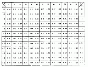
k = dimensionless coefficient to be determined from the
following table according to the ratio b/h. The
intermediate values are determined by interpolation
(linear or graphic). - Small tanks, which satisfy the following condition using the value of k corresponding to the angle of inclination of 30°, need not be included in computation:
where:
D min = minimum ship displacement in tons (metric tons); - The usual remainder of liquids in the empty tanks is not taken into account in computations.
4. Effect of timber deck cargo
In the case of ships carrying timber deck cargoes the Administration may allow account to be taken of the buoyancy of the deck cargo assuming that such cargo has a permeability of 25 per cent of the volume occupied by the cargo. Additional curves of stability may be required if the Administration considers it necessary to investigate the influence of different permeabilities and/or assumed effective height of the deck cargo.
(1) Where there is no limiting superstructure at the after end, the timber deck cargo shall extend at least to the after end of the aftermost hatchway.
Table of Values or Coefficient ‘K’ or Calculating
Free Surface Corrections
Previous Page | Next Page


