
- Article 18 – Prepare to stop at railway crossing sign (MUTCDC WB-6)
- Article 19 – Interconnection of traffic signals with warning systems
- Article 20 – Interconnected devices – Inspection and testing frequencies
The road authority or authority with jurisdiction (private or public) and the railway company or companies, as applicable, jointly determine the need and select the devices to be interconnected at a given grade crossing. This includes the need for pre-emption, the type of pre-emption, the time interval for any advance pre-emption, the exit gate clearance time, and the exit gate operating mode (AREMA 3.1.15). As a part of any pre-emption needs study, a thorough evaluation of all site-specific parameters, should be conducted, as described in Article 31 of this Handbook. This includes traffic signal operating sequences and timing, the use of pre-signals or queue-cutter signals, railroad warning devices, warning times and the impact of train operations on warning times.
If vehicle queue builds up inside the clear storage area of a highway intersection that is located at or near a grade crossing (with or without active warning devices) and that is not controlled by traffic signals, the road authority or authority with jurisdiction should consider installing a highway traffic signal and/or railroad active warning devices. See the Manual of Uniform Traffic Control Devices for Canada, 6th edition (MUTCDC) Part B: Traffic Control Signals, for specific information. Interconnection and pre-emption of the traffic signal controller should be provided if it falls within the requirements of the MUTCDC.
When a traffic control signal or other traffic control device is interconnected to a grade crossing warning system, a label must be installed in the traffic signal controller cabinet and the railway warning system housing informing maintenance personnel of the interconnection. The label must provide contact information for both the public agency responsible for the traffic signals and the railroad maintenance facility.
Article 18 - Prepare to Stop at Railway Crossing Sign (MUTCDC WB-6)
18.0 Where and When
A Prepare to Stop at Railway Crossing sign must be installed at new grade crossings with a warning system if:
- the road approach is an expressway, as defined in table 10-4 of the Grade Crossing Standards (GCS) (GCR 43 and 51).
- at least one set of front light units on the warning system is not clearly visible from the SSD of at least one of the lanes of the road approach; or
- weather conditions at the grade crossing repeatedly obscure the visibility of the warning system.
Note: Existing grade crossings must meet Articles 18.0 (a) to (c) by November 28th, 2022, or November 28th, 2024. (GCR 67 and 81). (See Article 2 for more information on amendments to the GCR timelines)
The Prepare to Stop at Railway Crossing Sign must meet the standards set out in the following articles.
18.1 General Requirements
The Prepare to Stop at Railway Crossing sign must be as shown in A3.6.6 of the Manual of Uniform Traffic Control Devices for Canada and meet the applicable specifications in article A1.6 of that Manual, and must operate:
- before the warning system light units are activated; and
- while the warning system light units are in operation.
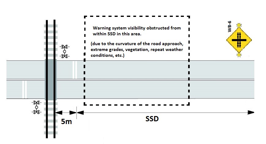
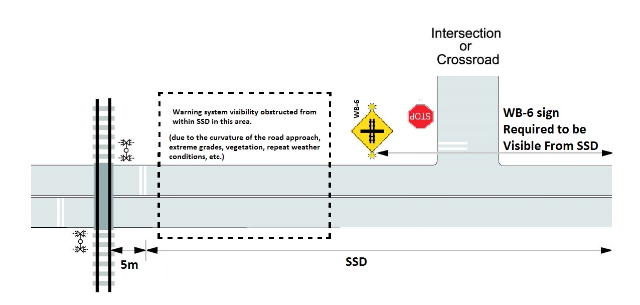
18.1.1 The Prepare to Stop at Railway Crossing sign (WB-6) should be installed at the point that marks the SSD as determined in Article 7.2 and shown in Figure 18-1 a). Where site-specific conditions warrant, the Prepare to Stop at Railway Crossing may be installed closer than SSD but must maintain visibility from the SSD as shown in Figure 18-1 b).
18.2 Advance Activation of sign
The advance activation time must be the greater of the time it takes a vehicle travelling at the road crossing design speed to pass a deactivated Prepare to Stop at Railway Crossing sign and to:
- clear the grade crossing before the arrival of railway equipment at the crossing surface, where there is a warning system without gates (TSSD, formula found below); or
- clear the grade crossing before the gate arms start to descend (TGSSD, formula found below), where there is a warning system with gates.
Formulas:
where:
SSD is calculated in accordance with Article 7.2
cd is calculated in accordance with Article 10.2.1
L is the length of the selected design vehicle.
where:
TGSSD is calculated in accordance with Article 10.4.1
18.3 Battery Backup
Where a Prepare to Stop at Railway Crossing sign is installed, four hours of continuous battery back-up power must be provided for its operation.
Note: This is a requirement for all Prepare to Stop at Railway Crossing signs installed after November 28th, 2014. This requirement does not apply to Prepare to Stop at Railway Crossings signs installed before November 28th, 2014; however, it is considered an engineering best practice. (See Article 2 for more information on amendments to the GCR timelines)
Plans and Documents
Plans and forms for Prepare to Stop at Railway Crossing signs, traffic signals that are interconnected with grade crossing warning systems and traffic signals installed in lieu of grade crossing warning systems must include, at a minimum:
- a location plan.
- a circuit and electrical plan.
- a description of the design timing sequencing and operational characteristics; and
- all other information necessary to carry out inspection, testing and maintenance in accordance with the GCS.
Alterations made to system components must be indicated on the plans. Such changes must be dated and initialed by the person making the change. When a change is made, an updated copy of the plans must be placed in the equipment housing as soon as possible (GCR93(3)).
Figure 18-1 Prepare to Stop at Railway Crossing Sign
a)
b)
Article 19 - Interconnection of Traffic Signals with Warning Systems
19.1 Where and When
Interconnection is to be provided at grade crossings where the railway design speed is 25 km/h (15 mph) or greater and where there is less than 30 m between the nearest rail of the crossing and the travelled way of an intersection with traffic signals.
Note: If interconnection is provided at a grade crossing even though it is not required under the GCR it should nonetheless meet the requirements for interconnection as per articles 19.2 to 19.4 of the GCS.
Also, if a traffic signal is installed at a grade crossing that meets the specifications set out in Article 19.1 of those Standards, the warning system must be interconnected with the traffic signal, and the interconnection must meet the standards set out below.
19.2 General requirements
Except where otherwise specified in the GCS or the GCR, the interconnection of a warning system with traffic signals at a grade crossing that meets the specifications of 19.1 must be designed and operated in accordance with Part 3.1.10 of the AREMA Communications and Signals Manual.
19.3 Minimum Timing Required
The interconnection of traffic signals with a warning system must
- provide sufficient time for vehicles to clear the grade crossing before the arrival of railway equipment at the crossing surface; and
- prevent movement of road traffic from the intersection towards the grade crossing.
19.4 Battery Backup
Where traffic signals are interconnected with a warning system, four (4) hours' worth of continuous battery back-up must be provided for the traffic signals.
Article 20 - Interconnected Devices – Inspection and Testing Frequencies
20.0 Testing and maintenance
See Article 2 for more information on amendments to the GCR timelines.
Except where otherwise specified in this Part, inspection, testing, and maintenance of the pre-emption of traffic signals by a grade crossing warning system must be in accordance with ITE Pre-emption Practices and the AREMA Communications and Signals Manual.
The Prepare to Stop at Railway Crossing sign and traffic signal pre-emption must be maintained, inspected, and tested in accordance with design plans and forms to ensure that they operate as intended (GCR 93(2), 95 and 96).
Note: All tests and maintenance conducted on the following devices should be conducted jointly by the railway and the responsible road authority. For more information, see Appendix L Guideline for Inspecting and Testing Pre-emption of Interconnected Traffic Control Signals and Grade Crossing Warning Systems.
20.0.1 The frequency requirements for inspections and tests for a Prepare to Stop at Railway Crossing sign, traffic signal pre-emption and traffic signals installed at a grade crossing in lieu of a warning system are specified in for railways and Table 20-1 for road authorities. Local circumstances may require inspection and testing more frequently than the maximum intervals specified herein.
20.0.2 The inspection and testing of the elements set out in column 2 of table 20-1 the GCS must be conducted at the frequency—as defined in table 17-1 of those Standards—set out in column 3 of Table 20-1[GCR 96(2)].
20.0.3 Information regarding the operating parameters of a traffic control device must be available on site for the road authority who inspects it [GCR 96(3)].
|
Item |
Elements and inspection and testing requirements |
Frequency |
|---|---|---|
|
1 |
Prepare to Stop at Railway Crossing signs and traffic signal pre-emption |
Immediately following installation, repair, adjustment, or maintenance |
|
2 |
Prepare to Stop at Railway Crossing sign: for visibility of light units |
Annually |
|
3 |
Traffic signals installed at a grade crossing in lieu of a warning system: for cleanliness, visibility of signal heads and physical damage |
Annually |
|
4 |
Traffic signal interconnection: for activation and operation with warning systems |
Annually |
|
5 |
Prepare to Stop at Railway Crossing sign: for activation and operation |
Annually |
Note: The road authority is responsible for the integrity of the cable between the warning system and the interconnected devices. Cable insulation resistance maintenance, inspection and testing should be completed at a frequency of no less than every 10 years as defined in Table 17-1of the GCS or this document.
See Appendix K and Appendix L for details pertaining to each test requirement set out in Table 20-1.