
- Article 5 – Crossing surface
- Article 6 – Road geometry
- Article 7 – Sightlines
- Article 8 – Signs
- Article 9 – Warning systems specifications
Public and private grade crossings can be viewed as simply a special type of roadway intersection, as three of the fundamental elements of a roadway intersection are present: the intersection itself; vehicles; and motorists/pedestrians. As with road intersections, motorists and pedestrians must yield the right of way to opposing traffic as appropriate. Unlike a regular roadway intersection, however, the opposing traffic—in this case the train—can only rarely yield the right of way to motorists/pedestrians. Motorists and pedestrians can alter direction and speed relatively quickly. Train operators, on the other hand, are restricted to travelling on a fixed path, and changing speed takes a much longer time. For this reason, motorists and pedestrians bear most of the responsibility for avoiding collisions with trains at grade crossings.
Section 26.2 of the Railway Safety Act (RSA) states that “the users of a road shall give way to railway equipment at a road crossing if adequate warning of its approach is given.” Adequate warning is therefore crucial at grade crossings. As well as a grade crossing's warning system, its design, its sightlines, its road approaches, and its crossing surface all contribute to providing adequate warning. Safety at grade crossings is therefore a shared responsibility. As such, sharing information about the site-specific parameters of a grade crossing is essential. The requirements of the Grade Crossings Regulations (GCR) cannot be properly met if each parameter is addressed separately, without regard to how a change in one could affect another. The following articles provide guidance as to the requirements for the proper design of all components of a grade crossing.
Section 11 of the RSA states that all work relating to railway works, including design, construction, evaluation, maintenance, and alteration, must be done in accordance with sound engineering principles, and that all engineering work relating to railway works must be approved by a professional engineer. More information regarding the application of section 11 of the RSA can be found on Transport Canada's website at: Guideline - Engineering Work Relating To Railway Works (Section 11 - Railway Safety Act) (canada.ca)
Article 5 - Crossing Surface
5.1 Crossings Surface (New grade crossings)
Applicable to all new grade crossings constructed on or after November 28, 2014, and to existing crossings to which changes were made. (See Article 2 for more information on amendments to the GCR timelines)
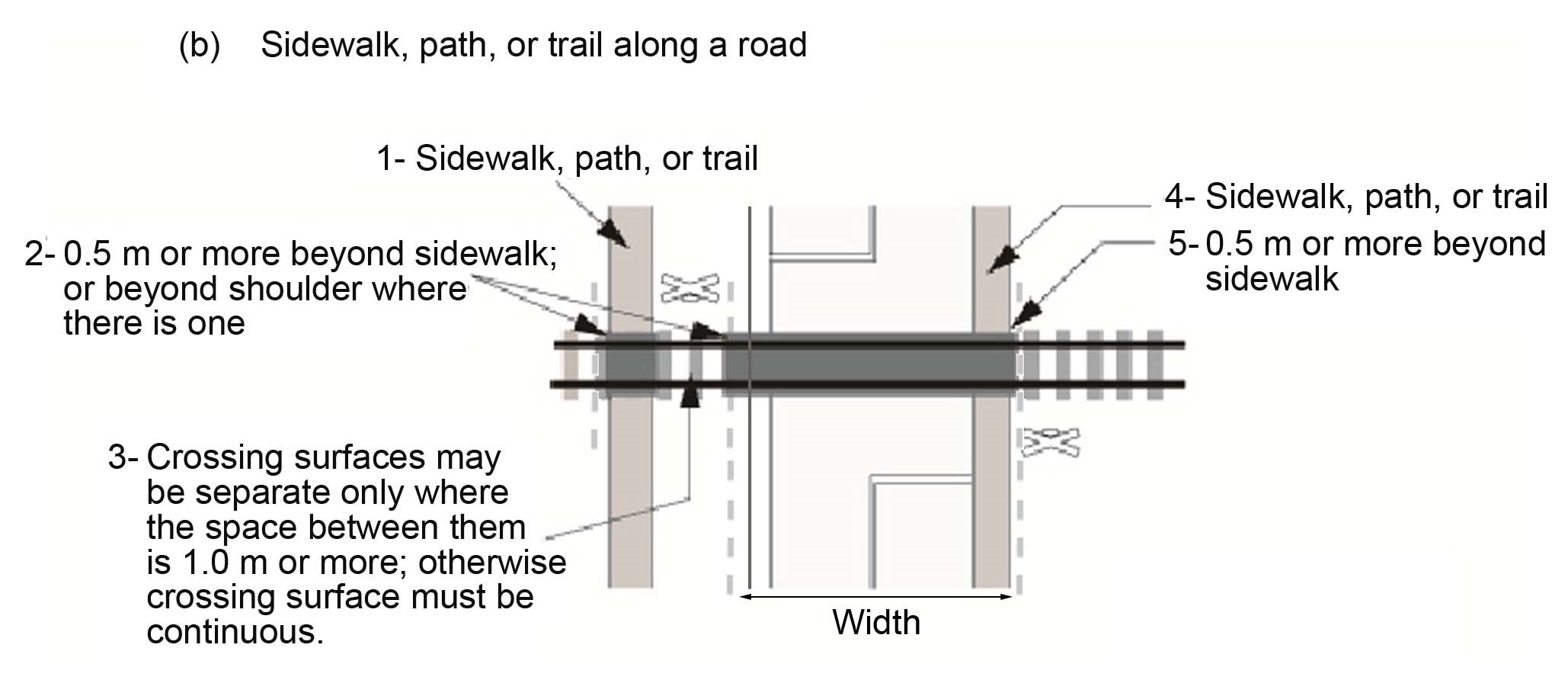
Crossing surface of a grade crossing, and a crossing surface of a sidewalk, path or trail must be as shown in Figure 5-1 and in accordance with Table 5-1, and must be smooth and continuous.
5.1.1 A smooth and continuous surface helps to ensure the safe and comfortable crossing by cyclists and pedestrians, including pedestrians with visual or mobility impairments. A smooth and level surface reduces the risk of tripping and falling for pedestrians, cyclists and users of wheelchairs or other mobility assistive devices.
5.1.2 As with the flangeway gap, the vertical difference between the rail and adjacent surfaces must be minimized. Vertical differences can be as critical as horizontal gaps because they can cause the swivel casters of wheelchairs or other assistive devices to turn sideways and drop into the gap.
The presence of vulnerable road users (VRU) at grade crossings in particular persons using assistive devices is a significant factor for assessing risk at a grade crossing. Special consideration should be given to accessibility needs for persons with mobility impairments.
Reference Appendix M of this Handbook to find further guidance on VRU treatments.
5.1.3 Grade crossing surface systems, including any Flangeway material components, gauge or field side of rail, should be electrically non-conductive so as not to interfere with train control or crossing signals operation.Footnote 6
Figure 5-1 Grade Crossing Surface Dimensions

|
a) Flangeway |
||
|
Width |
Minimum |
65 mm |
|
Maximum for |
||
|
Public sidewalks, paths or trails designated by the road authority for use by persons using assistive devices (only the portion of the crossing surface used by persons with assistive devices) |
75 mm |
|
|
All other grade crossings |
120 mm |
|
|
Depth: |
Minimum |
50 mm |
|
Maximum for: |
||
|
Public sidewalks, paths and trails designated by the road authority for use by persons using assistive devices (only the portion of the crossing surface used by persons with assistive devices) |
75 mm |
|
|
All other grade crossings |
No limit |
|
|
b) Field side gap A space is permitted on the outer side of the rail at rural locations, except for public sidewalks, paths or trails designated by the road authority for use by persons using assistive devices. |
||
|
Maximum width |
120 mm |
|
|
Maximum depth |
No limit |
|
|
c) Elevation of the top of the rail with respect to the crossing surface The top of the crossing surface must be installed as close as possible to the top of the rail within the wear limits below. |
||
|
Wear limits |
||
|
Public sidewalk, path or trail designated by the road authority for use by persons using assistive devices (only the portion of the crossing surface used by persons with assistive devices) |
||
|
|
Maximum distance of the top of the rail above crossing surface |
13 mm |
|
Maximum distance of the top of the rail below crossing surface |
7 mm |
|
|
All other public grade crossings: Maximum distance of the top of the rail above or below the crossing surface |
25 mm |
|
|
Private grade crossings: Maximum distance of the top of the rail above or below the crossing surface |
50 mm |
|
5.2 Crossing Surface (Existing grade crossings)
This section is applicable to existing grade crossings built before November 28, 2014. (See Article 2 for more information on amendments to the GCR timelines)
The crossing surface must be of a width that is equal to the width of the travelled way and shoulders of the road, plus 0.5 m on each side, measured at right angles to the centerline of the road, as shown in Figure 5-2 as applicable.
5.2.1 A smooth and continuous surface helps to ensure the safe and comfortable crossing by cyclists and pedestrians, including pedestrians with visual or mobility impairments. A smooth and continuous surface reduces the risk of tripping and falling, for pedestrians, cyclists and users of wheelchairs or other mobility assistive devices.
5.2.2 A flangeway must be provided between the gauge side of the rail and the road surface and must be between 65 mm and 120 mm wide, and between 50 mm and 75 mm deep.
5.2.3 As with the flangeway gap, the vertical difference between the rail and adjacent surfaces must be minimized. Vertical differences can be as critical as horizontal gaps because they can cause the swivel casters of wheelchairs or other assistive devices to turn sideways and drop into the gap.
Figure 5-2 Crossing Surface
a. 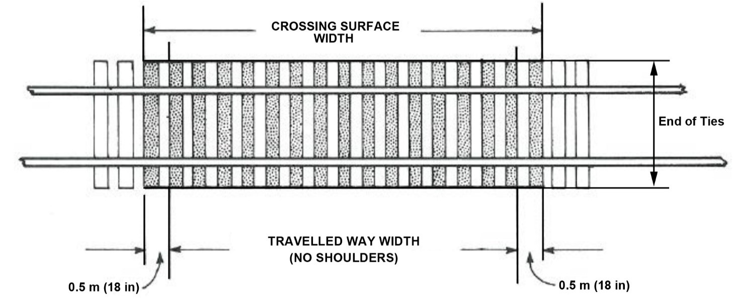
b. 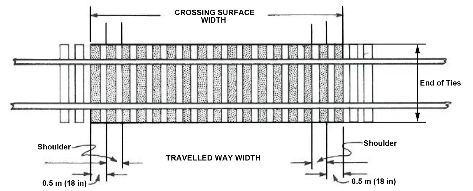
Article 6 - Road Geometry
6.1 Grade Crossings and Road Approaches
Applicable to all new grade crossings and to changes made at existing grade crossings to the location, gradient or crossing angle to improve the overall safety of the grade crossing (GCR 32 and 88) (see Article 2 for more information on amendments to the GCR timelines)
6.1.1 The horizontal and vertical alignment of the road approach and the crossing surface must be smooth and continuous.
6.1.2 The allowable difference between the road approach gradient and railway cross-slope, or the railway gradient and the road approach cross-slope, must be in accordance with Table 6-1.
6.1.3 The maximum gradients for road approaches must not exceed the following:
- ratio of 1:50 (2 per cent) within 8 m of the nearest rail and 1:20 (5 per cent) for 10 m beyond, at public grade crossings for vehicular use.
- ratio of 1:50 (2 per cent) within 8 m of the nearest rail and 1:10 (10 per cent) for 10 m beyond, at private grade crossings for vehicular use.
- ratio of 1:50 (2 per cent) within 5 m of the nearest rail at a sidewalk, path, or trail; and
- ratio of 1:100 (1 per cent) within 5 m of the nearest rail at a sidewalk, path or trail designated by the road authority for use by persons using assistive devices.
6.1.4 The width of the travelled way and shoulders of the crossing surface must not be less than the width of the travelled way and shoulders on the road approaches. This is to avoid creating an hour-glass effect.
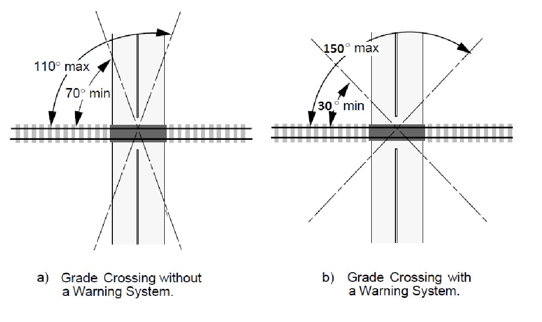
6.1.5 A grade crossing angle, measured from the tangent of the centreline of the road approach at the crossing surface to the tangent of the centreline of the line of railway, shall, where the railway design speed is more than 25 km/h (15 mph), be:
- not less than 70 and not greater than 110 degrees for grade crossings without a warning system (Figure 6-1 (a)) or
- not less than 30 and not greater than 150 degrees for grade crossings with a warning system (Figure 6-1 (b))
6.1.6 When a grade crossing is not a 90-degree intersection of track and road, the problems caused by vertical differences between railway and crossing surface are exacerbated. Vertical differences in skewed-angle grade crossings also increase the likelihood of cyclists losing control of their bicycles. Vertical differences should therefore be minimized at skewed-angle grade crossings.
The presence of vulnerable road users (VRU) at grade crossings in particular persons using assistive devices is a significant factor for assessing risk at a grade crossing. Special consideration should be given to accessibility needs for persons with mobility impairments.
Reference Appendix M of this Handbook to find further guidance on VRU treatments.
Figure 6-1 Maximum Crossing Angle: Grade Crossing
|
Classification |
Difference in Gradient (%) |
|---|---|
|
*Legend
Source: Geometric Design Guide for Canadian Roads, Transportation Association of Canada, September 1999 |
|
|
R L U |
2 |
|
R C U |
1 |
|
R C D |
1 |
|
R A U |
0 |
|
R A D |
0 |
|
R F D |
- |
|
U L U |
3 |
|
U C U |
2 |
|
U C D |
2 |
|
U A U |
0 |
6.2 Existing Grade Crossing Road Geometry
Grade crossings that existed prior to November 28, 2014, are grandfathered from some of the road geometry requirements set out in the GCR. However, existing grade crossings are required to satisfy Article 6.1 of the GCS by November 28, 2022, or November 28, 2024, depending on the specific physical and operational characteristics of the grade crossing. (See Article 2 for more information on amendments to the GCR timelines) Despite the phased-in approach to comply with the road geometry requirements, if at any time a grade crossings sees a change to its location, gradient or crossing angle, the grade crossing must comply with subsection 88(1) of the GCR. GCR 88(1) stipulates that the location, gradient and crossing angle are not required to comply fully with articles 6 or 11 of the GCS, but the changes to these elements of the grade crossings are required to be done in a manner that will improve the overall safety of the grade crossing.
Article 7 - Sightlines
Under the GCR, road authorities, private authorities and railway companies are required to maintain sightlines at grade crossings by November 28, 2022 or November 28th, 2024 (GCR23) depending on the specific physical and operational characteristics of the grade crossing. (See Article 2 for more information on amendments to the GCR timelines). The GCRset out standards for sightlines and their maintenance. Sightlines will be preserved by prohibiting the construction of buildings or structures, or the placement of objects, that obstruct them. Individuals will also be required to remove any trees or brush obstructing sightlines. Railway companies will be prohibited from leaving unattended any railway equipment that obstructs sightlines. For newly constructed grade crossings, or those that undergo alterations or operational changes, these requirements must be met immediately. Sections 24 to 28 of the GCRare in force as of day one, e.g., November 28, 2014 (GCR19 to 28).
Note: Sightlines are not required at a grade crossing which is equipped with an automatic warning system with gates. (GCR 22)
Note to Municipalities: Since November 28, 2014, section 24 of the GCRrequires that special attention be paid to land adjoining the land on which a line of railway is situated. Before a permit to build a permanent structure within the sightlines of a grade crossing is granted, the applicant should be advised that the GCRrequire the area within the sightline triangle shown of the GCS and this document remain clear at all times. At grade crossings equipped with an automatic warning system (with or without gates), while the sightline triangle is reduced, there remains requirements to see the warning system's front light units, as well as the Railway Crossing sign, from the stopping sight distance (SSD) (GCR 68 and 82).
Note: Under the GCR, sightlines are not required to be met until November 28, 2022 or November 28, 2024, depending on the specific physical and operational characteristics of the grade crossing, unless a new grade crossing is built or a change is made to any of the following elements at the grade crossing, in which case sightlines would be required at the time of the change (GCR28). (See Article 2 for more information on amendments to the GCR timelines).
The list of alterations or operational changes that will trigger a requirement for sightlines, are as follows:
- a line of railway is added within the sightlines.
- the class of track, as per column 1 (Table 7-1), changes as a result of a change in the maximum allowable operating speed as set out in column 2 or 3 of that table, as applicable.
- the design vehicle changes; or
- the specification in column B of GCS table 10-2 corresponding to the road approach changes because of an increase in the road crossing design speed, as per the characteristics set out in table 10-3 or table 10-4 of these Standards, as applicable.
Note to Railways: Temporary slow orders do not exempt a company from sightline requirements. Sightlines must be calculated based on railway design speed, which can differ from one direction to the other (GCR20 and 21).
7.1 General
7.1.1 Sightlines are to be measured from a point 1.05 m above the road surface to a point 1.2 m above top of lowest rail.
The 5 m mentioned in Figure 7-1 is to allow for different lengths of motor vehicle front ends.
7.1.2 For the purpose of sections 28(b) of the GCR, refer to the Class of Track Figure 7-1 below.
|
Column 1 |
Column 2 |
Column 3 |
|---|---|---|
|
Class of Track |
Maximum Operating Speed for Freight |
Maximum Operating Speed for Passenger |
|
Source: Rules Respecting Track Safety - Part II - Track Safety Rules |
||
|
Class 1 |
17 km/h (10 mph) |
25 km/h (15 mph) |
|
Class 2 |
41 km/h (25 mph) |
49 km/h (30 mph) |
|
Class 3 |
65 km/h (40 mph) |
97 km/h (60 mph) |
|
Class 4 |
97 km/h (60 mph) |
129 km/h (80 mph) |
|
Class 5 |
129 km/h (80 mph) |
153 km/h (95 mph) |
Figure 7-1 Minimum Sightlines - Grade Crossings
a) Sightlines for users stopped at a grade crossing (applicable to all quadrants)
b) Sightlines for users approaching a grade crossing (applicable to all quadrants)
7.2 Determination of Sightlines
In Figure 7-1,
- SSD is the stopping sight distance and is calculated using the following formula:
where:
d = braking distance (m) as per the Geometric Design Guide for Canadian Roads
V = road crossing design speed ( km/h )
- is the minimum distance along the line of railway from which a crossing user must see approaching railway equipment from the SSD and does not apply if the grade crossing is equipped with a Stop sign or warning system.
is equal to the distance required for the design vehicle at its road crossing design speed to go from the SSD to completely past the clearance point on the other side of the grade crossing.
where:
= railway design speed in km/h or mph
V = road crossing design speed ( km/h )
cd = grade crossing clearance distance (m)
L = length of the grade crossing design vehicle (m)
- is the minimum distance along the line of railway from which a crossing user must be able to see approaching railway equipment from the stopped position at a grade crossing.
is equal to the greater of the distances that railway equipment at the railway design speed will travel during
- the departure time for the grade crossing design vehicle calculated in accordance with Article 10.3.2, or
- the departure time for pedestrians, cyclists, and persons using assistive devices calculated in accordance with Article 10.3
must be calculated using the following formula:
where:
= railway design speed in km/h or mph
= the departure times, calculated in accordance with Article 10.3
A guide for determining minimum sightlines at grade crossings can be found on Transport Canada's website at Determining Minimum Sightlines at Grade Crossings Guide.
Obstructions to sightlines include but are not limited to:
- trees
- crops
- snowbanks
- brush
- buildings installed as of November 28th, 2014
- parked unattended equipment/vehicles
- any object that prevents a road user from knowing whether it is safe to proceed
- stored material
Where a grade crossing has inadequate sightlines and no warning system, and it is not physically or economically feasible to correct the deficiency, below are examples of what can be done to improve the grade crossing's safety:
- improve the roadway geometry.
- install appropriate warning signs (including active types and gates),
- reduce the posted roadway/railway design speed in advance of the crossing:
- advisory signing as a minimum.
- regulatory posted limit if it can be effectively enforced.
- close the crossing.
- reconfigure/relocate the crossing.
- Grade-separate the crossing (after considering review of location).
Article 8 - Signs
Note: Should a stakeholder decide to install any of the non-mandatory signs referred to in the GCR or GCS, such signs must nonetheless be installed in accordance with those documents (GCR 48 and 73).
8.1 Railway Crossing Sign and Number of Tracks Sign
See Article 2 for more information on amendments to the GCR timelines.
Note:For private grade crossings, this applies only when signs are installed.
8.1.1 Railway Crossing Sign
A sign providing warning of a grade crossing (Railway Crossing sign) must be as shown in Figure 8-1 a) (GCR 38, 48, 58 and 73) and must:
- have a retroreflective coating that covers the entire front surface of the sign.
- have a 50-mm border on the front of each blade, with transparent red ink silk-screen processed over sheeting material.
8.1.2 Number of Track Sign
A sign indicating the number of tracks at a grade crossing (Number of Tracks sign) must be as shown in Figure 8-1 b) (GCR 38, 48, 58 and 73) and must:
- have a retroreflective coating that covers the entire front surface of the sign.
- have a digit and symbol that is transparent red inked silk-screened processed.
- be installed on the supporting post of each Railway Crossing sign as shown in Figure 8-1 c).
- for grade crossings that existed prior to November 28th, 2014, be either red or black, unless a sign is replaced after November 28th, 2014, in which case it must comply with standard 8.1.2(b) (GCR 58, 73 and 86; GCS 4.1).
Note: Railway Crossing and Number of Track signs are not mandatory at private grade crossings. However, if such signs are installed at a private grade crossing, they must comply with standards 8.1.1 and 8.1.2 (GCR 48 and 73).
Figure 8-1 Railway Crossing and Number of Tracks Signs

Source: Grade Crossings Standards, January 1, 2019
8.1.3 Additional Requirements for Grade Crossings Without Warning Systems
Existing grade crossings and grade crossings installed or modified as of November 28th, 2022, or November 28th, 2024 require (see Article 2 for more information on amendments to the GCR timelines):
8.1.3.1 A 100-mm retroreflective strip must be applied on the back of each blade of the Railway Crossing sign, for the full length of each blade.
8.1.3.2 A 50-mm strip of silver white sheeting must be applied on the front and back of the supporting post, extending from no higher than 300 mm above the crown of the adjacent road surface to 70 mm above the centre of the Railway Crossing sign, and must be as shown in Figure 8-2.
Figure 8-2 Retroreflective Stripes on the Back of the Railway Crossing Sign and, on the Sign, Supporting Post (Public Grade Crossings without a grade crossing warning system)

Source: Grade Crossings Standards, January 1, 2019
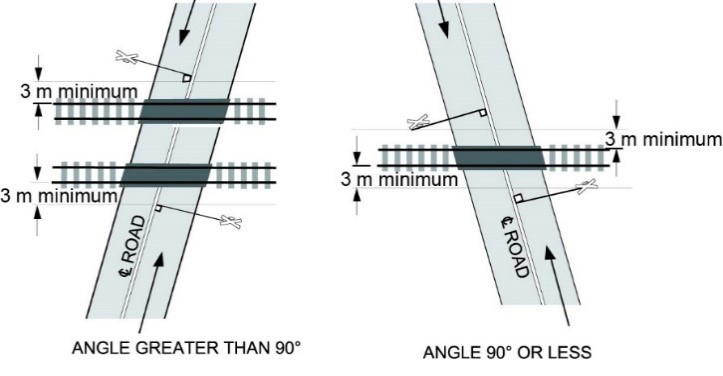
8.1.3.3 The Railway Crossing sign must be located:
- between 0.3 m and 2.0 m from the face of the curb or the outer edge of the road shoulder or, where there is no curb or shoulder, 2.0 m to 4.5 m from the edge of the travelled way: and
- not closer than 3 m measured to the nearest rail, as shown in Figure 8-3.
8.1.3.4 At public grade crossings and where provided at a private grade crossing, a sidewalk, path, or trail with a centerline that is at a distance of more than 3.6 m (12 ft.) from a Railway Crossing sign supporting post beside a road approach for vehicle traffic must have a separate Railway Crossing sign, as shown in Figure 8-3 (GCR38, 58 and 73; GCS 4.1.1(f)).
New grade crossings and grade crossings modified on or after November 28th, 2014 (see Article 2 for more information on amendments to the GCR timelines).
Figure 8-3 Location of Railway Crossing Signs (public grade crossings without warning systems)
a)
b)
Source: Grade Crossings Standards, January 1, 2019
8.1.4 Supporting Post Design Criteria
8.1.4.1 For new Railway Crossing sign supporting posts and when changes are made to an existing post supporting of a Railway Crossing or Number of Track sign, the supporting post must:
- unless the Railway Crossing sign is installed on the mast of a warning system, be of such construction that an 820-kg vehicle striking it at a speed of 32 km/h or greater will not have a change in velocity greater than 4.57 m/s. (GCR 38, 48 and 86; GCS 8.1).
The intent of Article 8.1.7(a) is to ensure that the support post will break safely when struck by a vehicle from any direction, to prevent potential injuries that such an impact with an unyielding structure could cause. Breakaway sign supports are designed and constructed to break or yield when struck by a vehicle. This type of supporting post is made by drilling through the horizontal axis of the post at locations determined by its size. Structurally the post must be able to hold the weight of the sign.
Table 8-1 provides a guide for determining the size of wooden post to use and the size of breakaway holes to drill at the base of the post 75 mm and 435 mm above finished grade, as shown in Figure 8-4.
Figure 8-4 Wooden Sign Post Breakaway Hole and Embedded Depth

8.1.5 Wood Preservative
Wood preservative should be in accordance with CAN/CSA-O80, Series-08, Use Category UC 4.1.
All wooden posts should be stamped for wood preservative treatment using a certification mark authorized by the Canadian Wood Preservers Bureau (CWPB). The wood preservative stamp should be visible after installation and located at least 1.8 m from the bottom of the post.
Cut ends and field-drilled holes should receive two applications of 2% copper naphthenate wood preservative. Field-applied wood preservative that encounters any metal components should be removed immediately.
|
Sign Support Requirements |
|||||||||||
|---|---|---|---|---|---|---|---|---|---|---|---|
|
Empadment Depth |
Dressed Post Size and Hole Diameter |
Note 2 |
Galvanized Lag Bolt Size |
||||||||
|
Max. Sign Dimensions |
Max. Sign Area |
||||||||||
|
E |
w |
b |
Hole Dia. |
B cm |
H cm |
A M2 |
Inch |
||||
|
Source: Ontario Provincial Standard Drawing 985.110 |
|||||||||||
|
920 |
89 |
89 |
N/A |
120 |
90 |
0,41 |
3/8 X 3 |
||||
|
1000 |
89 |
140 |
38 |
120 |
120 |
0,90 |
3/8 X 3 |
||||
|
1000 |
140 |
140 |
51 |
120 |
180 |
1,08 |
3/8 X 4 |
||||
|
1200 |
140 |
184 |
76 |
120 |
180 |
1,80 |
3/8 X 4 |
||||
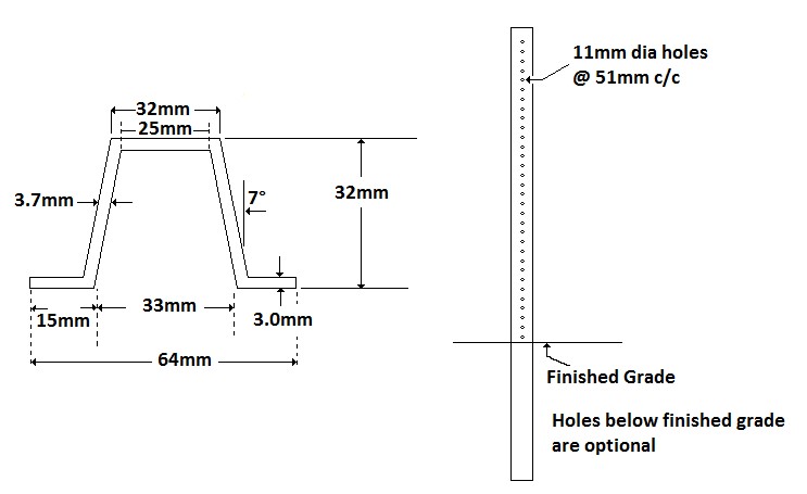
8.1.6 Metal U-Flange Posts
Metal U-Flange posts should only be used for Railway Crossing signs on low-speed roadways with barrier-type curbs and posted speeds of under 70 km/h.
U-Flange posts can be made of cold-formed or hot-formed steel. However, all metal posts must be hot dip galvanized after fabrication, in accordance with ASTM A123. Whether cold- or hot-formed steel is used, the tolerance for thickness should not be greater than ±0.38 mm and should be in conformance with Figures 8-5 and 8-6.
Specifications on how to treat damaged or cut areas of hot-dip galvanized coatings on any galvanized components, are provided under ASTM A780.
Figure 8-5 Cold Formed Steel Post Detail
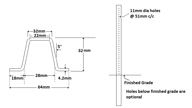
Figure 8-6 Hot Formed Steel Post Detail
8.1.7 Sign Hardware
All sign hardware should be hot dip galvanized in accordance with ASTM A153.
Posts should be plumbed within a tolerance of ±20 mm. The sign should be levelled on a multiple-post system within a tolerance of ±10 mm.
8.1.8 Retroreflective Material
The following applies to all new grade crossings, to existing crossings when a warranted change is made and, as of November 28th, 2022 or November 28th, 2024 for existing grade crossings (see Article 2 for more information on amendments to the GCR timelines).
8.1.8.1 Retroreflective material referred to in 8.1.1 to 8.1.4 must meet the specifications for Type IV material, white sheeting, as specified in sections 4.2.4 and 6.1.4 of ASTM D4956 when tested in accordance with the test methods for type IV material specified in sections 7 and 9 of that Standard (GCR 38, 48 and 62; GCS 8.1.9).
8.1.8.2 The retroreflection coefficient of the retroreflective material referred to in 8.1.8 is to be maintained above 50 per cent of the value specified for Type IV material specified in article 6.1.4 of ASTM D4956 GCR 38, 48 and 62: GCS 8.1.9).
8.2 Railway Crossing Ahead Sign and Advisory Speed Tab Sign
8.2.1 A sign providing advanced warning of a grade crossing (Railway Crossing Ahead sign) and a sign specifying a recommended speed (Advisory Speed Tab sign) must be as shown in articles A3.4.2 and A3.2.5 in the Manual of Uniform Traffic Control Devices for Canada and must meet the applicable standards set out in Article A1.6 of that Manual.
A Railway Crossing Ahead sign with an Advisory Speed Tab sign must be installed if:
- the installed Railway Crossing sign is not clearly visible within the SSD; or
- a motor vehicle on the road approach needs to reduce its speed to conform to the road crossing design speed (GCR 42, 50, 66 and 80; GCS 8.2).
8.3 Stop Ahead Sign
Note: A Stop Ahead sign must be installed if a Stop sign is installed and it is not clearly visible within the stopping sight distance (GCR41, 49, 65 and 79).
8.3.1 A Stop Ahead sign must be as shown in article A3.6.1 of the Manual of Uniform Traffic Control Devices for Canada and must meet the applicable standards set out in article A1.6 of that Manual.
8.4 Stop Sign
Stop signs, as traffic control devices, cause travel delays and can increase fuel consumption, vehicle emissions and collision frequency. They should therefore not be used indiscriminately. Stop signs are not intended as speed control devices, and their use should be limited to the control of right-of-way conflicts.
Stop signs should be used only where traffic engineering studies indicate that their use is warranted. These studies should consider such aspects as traffic speeds, traffic volumes, sightlines, and collision history. Stop signs are warranted at grade crossings without a warning system if the road crossing design speed is under 15 km/h.
8.4.1 A Stop sign must be as shown in article A2.2.1 of the Manual of Uniform Traffic Control Devices for Canada and must meet the applicable standards set out in Article A1.6 of that Manual. Where required by law, the word “Arrêt” will replace the word “Stop,” or may be added to the Stop sign.
8.4.2 When a Stop sign is installed on the same post as a Railway Crossing sign, it must be installed as shown in Figure 8-7 and maintained by the Railway (GCR 3(1)(a)(ii)).
8.4.3 Stop signs on their own post must not block the visibility of the Railway Crossings sign, and where there is a Railway Crossing sign, the Stop sign should be installed in advance of the Railway Crossing sign.
Figure 8-7 Stop Signs

8.5 Emergency Notification Sign (ENS)
As of November 28th, 2022, or November 28th, 2024, depending on the specific physical and operational characteristics of the grade crossing, railway companies will be required to install Emergency Notification signs (ENSs) at all public grade crossings. However, it is considered a best practice to install ENSs at all grade crossings, including private grade crossings. (See Article 2 for more information on amendments to the GCR timelines)
These signs provide all crossing users with the information needed to report/notify railway companies about emergencies or malfunctioning warning systems or any traffic control devices at grade crossings.
8.5.1 As of November 28th, 2022, or November 28th, 2024 an ENS that provides the railway company's emergency telephone number and the required information to positively identify the location of the grade crossing must be installed at all public grade crossings ((GCR sections 39, 63, 53(2) and 53(3)). (See Article 2 for more information on amendments to the GCR timelines).
- Parallel to the road, or
- On each side to the grade crossing, facing traffic approaching the grade crossing.
Best engineering practice is to install the ENS oriented to face the same direction as the other traffic control signs. (Perpendicular to the centre line of the road approach)
8.5.2 The ENS must be clearly legible.
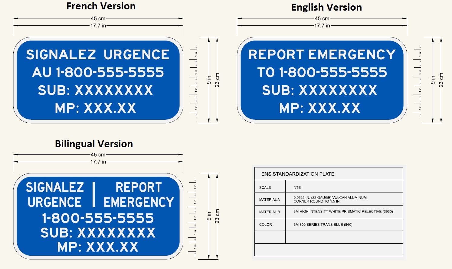
8.5.2.1 The ENS should include the following information/characteristics at a minimum:
- The railway company's emergency telephone number established to receive reports about emergencies or malfunctions of the warning system and the traffic control devices within the crossing approaches.
- The Crossing ID should preferably include a Mile Point and Subdivision name (Sub).
The wording should include the following at a minimum:
The word EMERGENCY (e.g., “REPORT EMERGENCY 1-800-555-5555”)
8.5.3 In order to be conspicuous, each ENS should:
-
Measure 30.5 cm (12 inches) wide by 22.86 cm (9 inches) high at a minimum.
Note: Proportional increases above the minimum sign dimensions to optimize the visibility of the ENS and/or to accommodate a bilingual message is permissible.
- Be retroreflective; making it conspicuous to all crossing users by day and night.
- Provide a minimum legible text (i.e., letters and numerals) with a character height not less than 2.54 cm (1 inch) for the sign information/message required above.
- Have white text on a blue background with a white border; and
- Be a traffic control type sign manufactured using the specifications for retroreflective sheeting material for traffic control signs as required by Grade Crossings Standards (GCS) Article 8.1.8. Decals should not be used unless they are constructed with materials meeting Article 8.1.8 of the GCS and are mounted on a ridged sign backer plate mounted in a manner to be read horizontally.
8.5.4 If the ENS is installed on the same mast/post as all the other railway signs, the ENSs should be placed, immediately below the Railway Crossing Sign, or where applicable, below the Number of Tracks Sign or Stop Sign, along the right side of each road/sidewalk/path or trail approach to the crossing.
For multi-lane road approaches, additional ENS should be considered.
If not installed on the same mast/post as all the other railway signs, the ENS should be located between 0.3 m and 2.0 m from the face of the curb or the outer edge of the road shoulder or, where there is no curb or shoulder, 2.0 m to 4.5 m from the edge of the travelled way while ensuring the sign does not obstruct other traffic control devices or warning system components.
While the ENS is permitted to be installed parallel to the road, to be conspicuous for all crossing users, the best engineering practice is to install the ENS orientated to face the same direction, as the other signs on the warning device mast/post (perpendicular to the centerline of the road approach). This orientation will provide visibility for all crossing users in a wide variety of situations. Minor variations may be justified in certain situations to optimize the visibility of the signs.
8.5.5 Many jurisdictions in Canada may require that signs, such as these, provide its information in both official languages. While the language (English or French) is not specified in the GCR, or GCS, the use of bilingual signs may be required depending on the applicable jurisdiction.
For convenience, French, English and Bilingual (French/English), examples of ENSs are shown in Figure 8-8 below.
Figure 8-8 Examples of Emergency Notification Signs
8.6 Low Ground Clearance Sign
The Low Ground Clearance at Railway Crossing sign indicates a roadway vertical alignment at a grade crossing that may cause the underside of a vehicle (especially long wheel-based vehicles) to encounter the road surface and/or the rails when crossing the railway.
Note: Installation instructions are provided in the Manual of Uniform Traffic Control Devices for Canada. Attention should be made to avoid obstructing the retroreflective material referred of other signs or warning system installations.
The Low Ground Clearance at Railway Crossing sign is illustrated in Figure 8-9.
Figure 8-9 Low Ground Clearance at Railway Crossin Sign (WA-52)

WA-52
750 mm x 750 mm
8.7 Second Train Event Warning Sign
The Second Train Event Warning sign and “ATTENTION 2 TRAINS” warning tab are used to alert pedestrians and drivers of the potential presence of a second train at a grade crossing.
- These signs should be used when two or more tracks allow for the movement of trains on both tracks at the same time and where the approach of a second train may immediately follow the departure of the first, such as near a train station or at a track junction and/or multiple track alignment (two tracks or more).
- The Second Train Event Warning sign is a diamond-shaped warning sign measuring a minimum of 450 mm by 450 mm; the “ATTENTION 2 TRAINS” warning sign is a rectangular tab measuring a minimum of 450 mm by 200 mm that emphasizes the warning.
- Both of these signs should be mounted as close as possible to the minimum height, e.g., two meters from the surface of the ground to the bottom of the sign, as specified at Article A6.10.3 of the Manual of Uniform Traffic Control Devices for Canada. If they are mounted higher than the minimum height, pedestrians may not see or may not notice the signs.
- These warning signs should be placed such that the nearest edge is not less than 0.3 m and not more than 1.0 m from the curb face. The signs should be placed a maximum of 5.0 m from the nearest rail (the closer to the crossing, the better, but the minimum railway clearance setbacks from the nearest rail must be respected).
-
The Second Train Event Warning sign should be installed and maintained by the road authority and coordinated with the railway company to ensure the signs are placed and maintained in a consistent manner and are highly visible to pedestrians. Signs to be installed are required to have all buried facilities identified and their location indicated prior to installation on any public, railway, or private land. This will prevent damage and unnecessary repairs.
Note: The Second Train Event Warning sign should be installed in a manner not to obstruct the retroreflective material referred to in sections 38 and 62 of the GCR, nor obstruct sightlines or the visibility of the Railway Crossing sign and or light units.
The Second Train Event Warning sign and “ATTENTION 2 TRAINS” tab and their typical installation are illustrated in Figures 8-10 and 8-11.
Figure 8-10 Second Train Event Warning Sign and "ATTENTION 2 TRAINS" Warning Tab
WC-27
450 mm x 450 mm
WC-27S
450 mm X 200 mm
Source: Manual of Uniform Traffic Control Devices for Canada, Article A6.10.3.
Figure 8-11 Second Train Event Warning Sign Installation
8.8 Pavement Markings
Pavement markings are used to supplement the regulatory and warning messages presented by crossing signs and signals. Pavement markings have limitations in that they may be hidden by snow, may not be clearly visible when wet, and may not be very durable when subjected to heavy traffic.
Pavement markings in advance of grade crossings should consist of an X, as shown in Figures 8-12 and 8-13. These pavement markings should be placed on each approach lane on all paved approaches to grade crossings where crossing signals or automatic gates are located, and at all other crossings where the prevailing speed of roadway traffic is 40 km/h or greater.
Pavement markings should conform to Part C of the Manual of Uniform Traffic Control Devices for Canada.
For grade crossings without a warning system, stop bars should be installed 5 m from the nearest rail, perpendicularly to the paved road approach. Where the Railway Crossing sign or signal mast is installed more than 3 m in advance of the nearest rail, the stop bars should be located a minimum of 2 m in advance of the centre of the Railway Crossing sign or signal mast on the paved road approaches, as shown in Figures 8-12 and 8-13.
The presence of vulnerable road users (VRU) at grade crossings in particular persons using assistive devices is a significant factor for assessing risk at a grade crossing. Special consideration should be given to accessibility needs for persons with mobility impairments.
Reference Appendix M of this Handbook to find further guidance on VRU treatments.
Figure 8-12 Pavement Markings (left hand angle)
Figure 8-13 Pavement Markings (right-hand angle)

8.9 Rumble Strips
In addition to stop bars and other pavement markings on the road approaches, rumble strips may be installed as an added safety measure, to make drivers aware of their surroundings. For this, an engineering study may be required.
Note: Rumble strips are not to be used to replace any component of a warning system, only as an added feature.
Article 9 - Warning System Specifications
The following articles set out the minimum specifications which may require a warning system to be installed, with or without gates, for public and private grade crossings.
This section applies to all new grade crossings (See Article 2 for more information on amendments to the GCR timelines).
The GCR do not require that existing grade crossings be upgraded to meet these standards. However, whenever new information regarding an existing grade crossing is provided/received that could change its requirements, it is considered a best engineering practice for both the railway and the applicable authority to review the criteria below, and any other elements that may impact safety, on a frequent basis (as described in Article 31 of this Handbook), and upgrade as needed to improve the overall safety at the location.
9.1 Criteria for requiring a warning system without gates (public grade crossings):
- The forecast cross-product is 2,000 or more; or
- there is no sidewalk, path or trail and the railway design speed is greater than 129 km/h (80 mph); or
- there is a sidewalk, path or trail and the railway design speed is greater than 81 km/h (50 mph); or
- the railway design speed is greater than 25 km/h (15 mph) but less than the railway design speed referred to in (b) or (c), as applicable, and
- there are two or more lines of railway where railway equipment may pass each other, or
- the distance as shown in Figure 9-1 between a Stop sign at an intersection and the nearest rail in the crossing surface is less than 30 m, or
- in the case of an intersection with a traffic signal, the distance between the stop line of the intersection and the nearest rail in the crossing surface, as shown in Figure 9-1, is less than 60 m or, where there is no stop line, the distance between the travelled way and the nearest rail in the crossing surface is less than 60 m.
9.2 Criteria for requiring a warning system with gates (public grade crossings):
9.2.1 A warning system is required under Article 9.1, and
- the forecast cross-product is 50,000 or more; or
- there are two or more lines of railway where railway equipment may pass each other; or
- the railway design speed is greater than 81 km/h (50 mph); or
- the distance as shown in Figure 9-1 between a Stop sign at an intersection and the nearest rail in the crossing surface is less than 30 m: or
- in the case of an intersection with a traffic signal, the distance between the stop line of the intersection and the nearest rail in the crossing surface, as shown in Figure 9-1, is less than 60 m or, where there is no stop line, the distance between the travelled way and the nearest rail in the crossing surface is less than 60 m.
9.3 Criteria for requiring a warning system without gates (private grade crossings):
9.3.1 the forecast cross-product is 2,000 or more; or
9.3.2 the railway design speed is greater than 25 km/h (15 mph), and
- the forecast cross-product is 100 or more and there are two or more lines of railway where railway equipment may pass each other; or
- the forecast cross-product is 100 or more and grade crossing does not include a sidewalk, path or trail and the railway design speed is greater than 129 km/h (80 mph); or
- the grade crossing includes a sidewalk, path or trail and the railway design speed is greater than 81 km/h (50 mph).
9.4 Criteria for requiring a warning system with gates (private grade crossings):
9.4.1 A warning system is required under Article 9.3, and
- the forecast cross-product is 50,000 or more; or
- there are two or more lines of railway where railway equipment may pass each other; or
- the railway design speed is greater than 81 km/h (50 mph).
9.5 Criteria for requiring a warning system without gates (grade crossings that are a sidewalk, path, or trail):
- The sidewalk, path or trail is outside the island circuit of an adjacent warning system, and
- the railway design speed is greater than 81 km/h (50 mph).
9.6 Criteria for requiring a warning system with gates (grade crossings that are a sidewalk, path, or trail):
- The sidewalk, path or trail is outside the island circuit of an adjacent warning system, and
- the railway design speed is greater than 25 km/h (15 mph), and
- there are two or more lines of railway.
9.7 Criteria for requiring a warning system to be interconnected with traffic signals (all types of grade crossings) (GCR 46, 56 and 100(2)):
- The travelled way of an intersection controlled by traffic signals is within 30 m of the nearest rail of the grade crossing: or
- there are repeat instances of road traffic queuing over the grade crossing; or
- road traffic backed up from a nearby downstream grade crossing could interfere with signalized road traffic intersections; or
-
operational conditions exist that warrant the interconnection of a warning system with traffic signals.
Note: See Part E of this document for more information pertaining to interconnected devices.
9.8 The criteria for a grade crossing requiring a warning system to be interconnected with a Prepare to Stop at Railway Crossing sign are as follows (GCR 43, 51, 67 and 81):
- The road approach is an expressway considering the characteristics set out for expressways in Table 10-4 of the GCS; or
- at least one set of front light units of the warning system is not clearly visible within the SSD of at least one of the lanes of the road approach; or
- the weather conditions at the grade crossing repeatedly obscure the visibility of the warning system; or
-
operational conditions exist that warrant the interconnection of a warning system with a Prepare to Stop at Railway Crossing sign.
Note: See Part E of this document for more information pertaining to interconnected devices.
Figure 9-1 Proximity of Warning Systems to an Intersection with Stop Sign or Traffic Signal
a) Intersection with Stop sign

b) Intersection with Traffic Signal
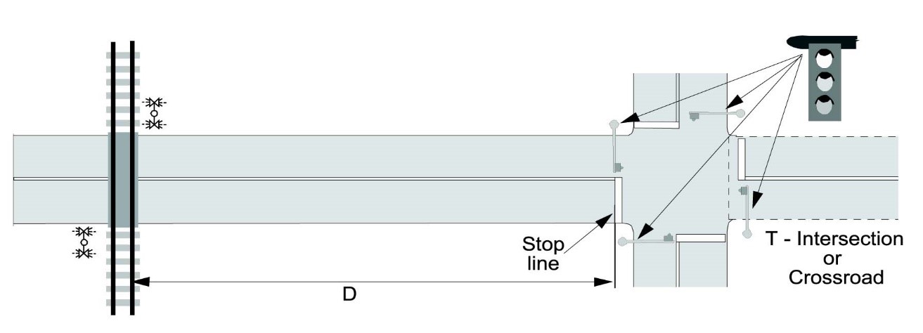
Source: Grade Crossings Standards, January 1, 2019