
- Appendix A – Light emitting diode (LED) signal modules
- Appendix B – Limited use warning systems and signs
- Appendix C – Limited use warning system with walk light
- Appendix D – Whistling cessation
- Appendix E – Guideline for determining minimum sightlines at grade crossings
- Appendix F – Rail safety regional contacts
- Appendix G – Sharing of information form road authority
- Appendix H – Sharing of information form railway
- Appendix I – Canadian grade crossing detailed safety assessment field guide
- Appendix J – Testing requirements (railway)
- Appendix K – Testing requirement (road authority)
- Appendix L – Guideline for inspecting and testing pre-emption of interconnected traffic control signals and grade crossing warning systems
- Appendix M – Supplemental engineering design guidance for vulnerable road users at grade crossings
Appendix A - Light Emitting Diode (LED) Signal Modules
1. Definitions
Candela (cd) – SI unit of luminous intensity. The candela is the luminous intensity, in each direction, of a source that emits monochromatic radiation of frequency 540 nm and that has a radiant intensity in that direction of 1/683 W per steradian (1 cd = 1 lm/sr).
Lumen (Lm) – SI unit of luminous flux. Luminous flux emitted in unit solid angle [steradian (sr)] by a uniform point source having a luminous intensity of 1 candela (1 lm = 1 cd x 1 sr).
Luminance Lv - (in a given direction, at a given point on a real or imaginary surface) – quantity defined by the formula:
where:
dΦv is the luminous flux transmitted by an elementary beam passing through the given point and propagating in the solid angle dΩ containing the given direction; dA is the area of a section of that beam containing the given point; θ is the angle between the normal to that section and the direction of the beam (footlambert, cd/m2).
Luminous Efficacy or Radiation (K) – the luminous flux Φv divided by the corresponding radiant flux Φe (K = Φv/Φe).
Luminous Intensity (Iv) (of a source in a given direction) – the luminous flux dΦv leaving the source and propagating in the element of solid angle dΩ containing the given direction, divided by the element of solid angle (Iv = dΦv / dΩ candela).
Luminous Flux (Φv) – quantity derived from radiant flux Φe by evaluating the radiation according to its action upon the CIE standard photometric observer (lumen).
Rated Voltage – the nominal or design operating voltage of the LED signal module; the voltage at which rated watts, candelas, and life are determined.
Rated Watts – the average initial power (watts) consumed when the lamp is operated at rated voltage.
2. Photometric Requirements
2.1 Luminous Intensity
When LED signal modules are in use at a warning system, they must meet the minimum luminous intensity values shown in Appendix Table A-1.
|
|
0˚ |
5˚Left (L)/Right (R) |
10˚L/R |
15˚L/R |
20˚L/R |
25˚L/R |
30˚L/R |
|---|---|---|---|---|---|---|---|
|
0˚ |
400 |
375 |
250 |
150 |
75 |
40 |
15 |
|
5˚Down (D) |
350 |
325 |
250 |
150 |
75 |
40 |
15 |
|
10˚D |
130 |
125 |
110 |
85 |
60 |
35 |
15 |
|
15˚D |
45 |
40 |
35 |
30 |
25 |
20 |
15 |
|
20˚D |
15 |
15 |
15 |
15 |
15 |
15 |
10 |
2.2 Chromaticity
A signal module must produce a uniform red-light output as specified in Article 4.2 of the Vehicle Traffic Control Signal Heads – Light Emitting Diode Circular Supplement, published by the Institute of Transportation Engineers, dated June 2005.
2.3 Uniformity
The ratio of the greatest and least luminance on the signal module must not be more than 5:1, when measured over average areas of 500 mm2.
2.4 Rise/Fall Time
The maximum rise time from zero intensity to full intensity, and the maximum fall time from full intensity to zero intensity, must be 75 milliseconds.
3. Physical And Mechanical Requirements
3.1 LED Signal Module Design
3.1.1 The LED signal module must be designed to fit the grade crossing light unit housings, described in Part 3.2.35 of the AREMA Communications and Signals Manual (cited in Part A), without requiring modification of the mechanical, structural, or electrical components.
3.1.2 The LED signal module must be either 200 mm or 300 mm in size.
3.1.3 The LED signal module must have either a clear or a red lens.
3.1.4 Any gasket or similar sealing provisions must be made of a material as specified in Part 15.2.10 of the AREMA Communications and Signals Manual (cited in Part A).
3.2 Environmental Requirements
3.2.1 The LED signal module must operate over an ambient temperature range of -40°C (-40°F) to 70°C (158°F) in accordance with sections 1 to 3 of the "Method 1010.8 Temperature Cycling", dated June 18, 2004, of MIL-STD-883H, Test Method Standard, Microcircuits, published by the United States Department of Defense, dated February 26, 2010 and must satisfy the failure criteria set-out in Article 3.3 of that standard, and any reference to end-point measurements and examinations are to be read as those provided by the supplier.
3.2.2 The LED signal module must be protected against dust and moisture intrusion in a Type 4 enclosure in a manner that meets the requirement of Article 8.6.2 of the Canadian Standards Association standard CAN/CSA-C22.2 No. 94.2-07 entitled Enclosures for Electrical Equipment, Environmental Considerations, as amended from time to time, when tested in accordance with Article 8.6.1 of that Standard.
3.2.3 The LED signal module must meet mechanical vibration and shock requirements as specified in Part 11.5.1 of the AREMA Communications and Signals Manual (cited in Part A).
3.2.4 The LED signal module lens must be UV stabilized.
3.3 Identification
3.3.1 The LED signal module must have a label containing the following information:
- the LED colour.
- the beam deflection classification.
- the operating voltage.
- the current consumption at operating voltage.
- the module's serial number; and
- the date of manufacture.
3.3.2 If the module or its components require orientation, they must be prominently and permanently marked with an indexing arrow.
4. Electrical Requirements
4.1 Transient Voltage Protection
LED signal module circuitry must include voltage surge protection as specified in Part 11.3.3 of AREMA Communications and Signals Manual (cited in Part A).
4.2 LED Drive Circuitry
LED signal module circuitry must operate as specified in Part 3.2.35ofthe AREMA Communications and Signals Manual (cited in Part A).
4.3 Dielectric and Electromagnetic Interference
LED signal module circuitry must conform to dielectric and electromagnetic interference requirements for Class B equipment in Part 11.5.1 of AREMA Communications and Signals Manual (cited in Part A).
Appendix B - Limited Use Warning Systems and Signs
If the grade crossing provides access to fewer than three private dwellings and does not provide access to a business, a limited-use warning system and signs that meet the standards set out in Appendix B of the Grade Crossings Standards (GCS) may be installed at the grade crossing instead of the warning system referred to in the Grade Crossings Regulations (GCR).
1. Operating Requirements
1.1 Battery backup for a minimum of 24 hours of normal railway operations must be provided.
1.2 Power monitor lights must be provided.
2. Warning System Requirements
2.1 Limited Use Warning System must meet the specifications of Articles 12 to 16 of the GCS except:
- it does not require a gate.
- the height of the light unit may be different than that stated in the AREMA's Communications and Signals Manual or the GCS as to improve conspicuity.
- the signal mast may be located closer to the road approach than that stated in the AREMA's Communications and Signals Manual or the GCS to improve conspicuity.
- A bell is not required; and
- Front and back lights must be provided on each warning signal assembly.
3. Signage Requirements
3.1 An Emergency Notification sign must be installed at each location.
3.2 A sign indicating that the road is private must be posted near the entrance to the private road.
Appendix C - Limited Use Warning System with Walk Light
If they meet the standards set out in Appendix C of the Grade Crossing Standards (GCS), reproduced below, signs and a limited-use warning system with a walk light may be installed at a grade crossing instead of the warning system referred to in the Grade Crossings Regulations (GCR), if:
- access to the road is controlled by a locked barrier; or
- the grade crossing is for the exclusive use of the private authority and is not used by the public.
1. Operating Requirements
1.1 Battery backup of a minimum of 8 hours must be provided.
1.2 Power monitor lights must be provided.
2. Signal Requirements
2.1 A Limited Use Warning System with Walk Light must meet the specifications below:
- must be installed on each side of the grade crossing and face a crossing user approaching the grade crossing.
- must include a signal head that displays a signal indicating to a crossing user that it is safe to proceed when railway equipment is not approaching. This signal head must be extinguished when railway equipment is approaching.
- The signal head must be as specified in sections 2 to 5, excluding the last paragraph of section 4.1.1, of the ITE “Pedestrian Traffic Control Signal Indications - Part 2: Light Emitting Diode (LED) Pedestrian Traffic Signal Modules” prepared by the Joint Industry and Traffic Engineering Council Committee, published by the Institute of Transportation Engineers, dated March 19, 2004, except for the following aspects:
- 12VDC pedestrian module is to be used instead of a 120VAC input voltage.
- the operating voltage range must be 9 – 15VDC, and the light must shut off at 7.3VDC or less; and
- References to “LED Pedestrian Signal Module” or “Module” are to be read as “Walk Light”.
- The walk light indicating that it is safe to proceed must be extinguished a minimum of 20 seconds plus the clearance time before the arrival of railway equipment at the crossing surface.
- The clearance time must be based on design vehicle and must be calculated in accordance with Article 10 of the GCS.
3. Signage and Post Requirements
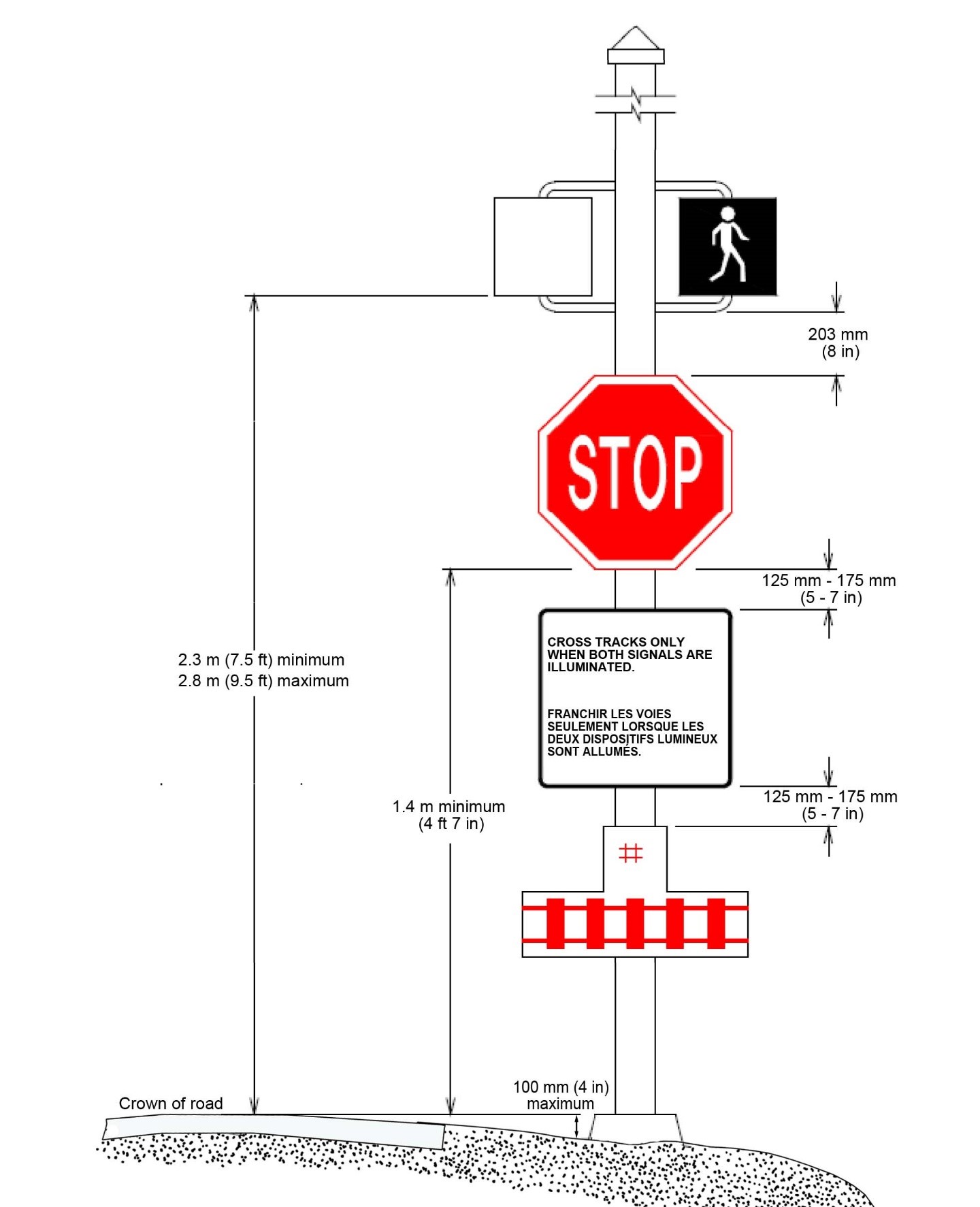
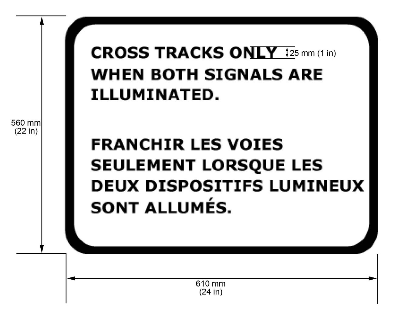
3.1 Signage indicating how to use a Limited Use Warning Systems with Walk Light must be as shown in Appendix Figure C-2 and must:
- be mounted on the mast under the walk light signal head as indicated in Appendix Figure C-1; and
- have a silver background that is reflective with silk screened black or vinyl lettering. Where required by law, the word “Arrêt” may replace the word “Stop” or may be added to the Stop Sign.
3.2 A Stop sign must be as shown in Article A2.2.1 of the Manual of Uniform Traffic Control Devices for Canada and must meet the applicable specifications A1.6 of that Manual. Where required by law, the word “Arrêt” will replace the word “Stop” or may be added to the Stop sign. The Stop sign must be mounted on the mast as shown in Appendix Figure C-1.
3.3 An Emergency Notification sign must be located at each Limited Use Warning System with Walk Light Assembly.
Appendix Figure C-1 Limited Use Warning System with Walk Light Assembly
Appendix Figure C-2 Instruction Sign
Appendix D - Whistling Cessation
Train whistling is an important way to keep drivers, cyclists, and pedestrians safe. The Canadian Rail Operating Rules require all trains to whistle whenever they approach a public grade crossing.
In some cases, train whistles bother people who live nearby. Municipalities may wish to stop the whistling to provide residents with relief from the noise. Please visit Transport Canada's website for more information.
Appendix E - Guideline for Determining Minimum Sightlines at Grade Crossings
To view the complete guide to determining minimum sightlines at grade crossings for road authorities and railway companies please visit the following website.
Appendix F - Rail Safety Regional Contacts
Headquarters
Director, Safety Policy & Regulatory Affairs
Enterprise Building, Minto Place, 427 Laurier Avenue West, 14th Floor
Ottawa ON K1A 0N5
Phone: 613-990-8690, Fax: 613-990-7767
Rail Safety Regional Office's
Atlantic Region
Regional Director
95 Foundry Street, PO Box 42
Moncton, NB, E1C 8K6
Tel.: 506 851-7040, Fax: 506 851-7042
Ontario Region
Regional Director
4900 Yonge Street, 3rd Floor
North York, ON, M2N 6A5
Tel.: 416 973-9820, Fax: 416 973-9907
Prairie and Northern Region
Regional Director
McDonald Building, 344 Edmonton Street, 3rd Floor
Winnipeg, MB, R3B 2L4
Tel.: 1-888-463-0521, Fax: 204 983-8992
Pacific Region
Regional Director
2010-7445 132nd Street
Surrey, BC, V3W 1J8
Tel.: 604 666-0011, Fax: 604 666-7747
Quebec Region
Regional Director
700 Leigh-Capreol Place
Dorval, QC, H4Y 1G7
Tel.: 514 633-3400, Fax: 514 633-3569
Appendix G - Sharing Of Information Form Road Authority
In accordance with Transport Canada's Grade Crossings Regulations
This form may be used by the Road Authority when sharing information with a Railway for the purpose of complying with sections 12 to 18 of the Grade Crossings Regulations (GCR). The Road Authority Sharing of Information Form Job Aid can be referenced to complete the forms.
|
SECTION 1 – General |
||||||||||||||||||
|---|---|---|---|---|---|---|---|---|---|---|---|---|---|---|---|---|---|---|
|
1. Road Authority: |
2. Date of Submission (yyyy/mm/dd): |
|||||||||||||||||
|
3. Road Authority Contact Information |
||||||||||||||||||
|
Title (optional): |
||||||||||||||||||
|
Name: |
Mailing Address: |
|||||||||||||||||
|
|
|
|||||||||||||||||
|
E-mail Address: |
||||||||||||||||||
|
|
||||||||||||||||||
|
Telephone Number: |
||||||||||||||||||
|
|
||||||||||||||||||
|
Additional Road Authority Contact Information (in case of emergency) |
||||||||||||||||||
|
Title (optional): |
||||||||||||||||||
|
Name: |
Mailing Address: |
|||||||||||||||||
|
|
|
|||||||||||||||||
|
E-mail Address: |
||||||||||||||||||
|
|
||||||||||||||||||
|
Telephone Number: |
||||||||||||||||||
|
|
||||||||||||||||||
|
4. Railway Company: |
||||||||||||||||||
|
|
||||||||||||||||||
|
Crossing Form |
Crossing No. ___________of___________ |
|||||||||||||||||
|
SECTION 2 – Grade Crossing Location (At least two [2] of the four [4] fields must be completed to identify the grade crossing location) |
||||||||||||||||||
|
5. Railway Subdivision & Mileage |
1 |
|||||||||||||||||
|
6. Latitude & Longitude |
2 |
|||||||||||||||||
|
7. Roadway Name |
3 |
|||||||||||||||||
|
8. City or Town Name |
4 |
|||||||||||||||||
|
SECTION 3 – Reason(s) for Sharing Information with the Railway (Select all that apply and provide details below) |
||||||||||||||||||
|
9. Information must be shared for existing public grade crossings no later than two years of the GCRcoming into force. (e.g., by November 28th, 2016) Ref. (GCR 12. (3)) |
||||||||||||||||||
|
10. Receipt of a notice from a railway company, under section 3 of the Notice of Railway Works Regulations. Ref. (GCR 12. (2)) |
||||||||||||||||||
|
11. A change in the design vehicle and the sightlines at the grade crossing, which must meet the requirements in section 20 of the GCR Ref. (GCR13 GCR28. (c)) |
||||||||||||||||||
|
12. An increase in the design speed of the road crossing, which will result in a change to the road approach's classification as set out in column B of the Table 10-2 of the Grade Crossings Standards (GCS). Ref. (GCR13 GCR28. (d)) |
||||||||||||||||||
|
13. The location, gradient or crossing angle of a grade crossing has changed, and Articles 6 and 11 of the GCS must be applied in a manner that improves the overall safety of the grade crossing. Ref. (GCR13 GCR 88. (1)) |
||||||||||||||||||
|
14. An increase of the absolute gradient of a road approach to an existing grade crossing which meets the standards set out in Article 6.3 of the GCS. Ref. (GCR 13 GCR88. (2)) |
||||||||||||||||||
|
15. The number or width of traffic lanes of a road approach increases, or a shoulder is added, or a shoulder's width is increased. The grade crossing must meet the standards set out in Articles 5.1 and 6.4 of the GCS. Ref. (GCR 13 GCR89) |
||||||||||||||||||
|
16. A traffic signal is installed at a grade crossing that corresponds to the specifications set out in Article 19.1 of the GCS, the warning system must be interconnected with the traffic signal, and the interconnection must meet the standards set out in Articles 19.2 to 19.4 of the GCS. Ref. (GCR 13 GCR90) |
||||||||||||||||||
|
17. A change in the design vehicle, which has resulted in a change to the period of time that the warning system must operate, before railway equipment reaches the crossing surface and therefore must meet the standards set out in Article 16.1 of the GCS. Ref. (GCR 13 GCR91) |
||||||||||||||||||
|
Details with respect to the change(s) selected: |
||||||||||||||||||
|
SECTION 4 – Notification of Other Changes (Select all that apply and provide details below) |
||||||||||||||||||
|
18. An increase in the road crossing design speed at a public grade crossing. (If this change is selected, the following fields in this form must be completed: SECTION 2, SECTION 5 [26] and SECTION 6 [30 & 32].) Ref. (GCR14) |
||||||||||||||||||
|
19. An interconnected traffic signal referred to in Article 19 of the GCS, or a Prepare to Stop at Railway Crossing sign, is installed or is changed at a public grade crossing. (If this change is selected, the following fields in this form must be completed: SECTION 2, SECTION 6 [33] and SECTION 7 [34].) Ref. (GCR15) |
||||||||||||||||||
|
20. If a road at a public grade crossing is transferred from one road authority to another, the information below must be provided. Ref. (GCR17) |
||||||||||||||||||
|
Contact information (name and Title): |
|
|||||||||||||||||
|
Road Authority Name: |
|
|||||||||||||||||
|
Address: |
|
|||||||||||||||||
|
Telephone Number: |
|
|||||||||||||||||
|
E-mail Address: |
|
|||||||||||||||||
|
E-mail Address: |
|
|||||||||||||||||
|
Date of Transfer: |
|
|||||||||||||||||
|
Details with respect to the change(s) selected:
|
||||||||||||||||||
|
SECTION 5 – Railway Crossing Details |
||||||||||||||||||
|
21. Total Number of Traffic Lanes |
22. Annual Average Daily Traffic (AADT) |
23. Existing Roadway Width (m) |
24. Grade Crossing Angle (°) |
|||||||||||||||
|
|
|
|
|
|||||||||||||||
|
25. Road Approach Information |
||||||||||||||||||
|
Column A |
Column B |
Column C |
||||||||||||||||
|
Rural |
Local |
Divided |
||||||||||||||||
|
Collector |
||||||||||||||||||
|
Urban |
Arterial |
Not Divided |
||||||||||||||||
|
Expressway |
||||||||||||||||||
|
Freeway |
||||||||||||||||||
|
26. Average Approach Gradient |
27. Existing Shoulder Width |
28. Path or Sidewalk |
||||||||||||||||
|
Approach 1 |
Approach 2 |
Approach 1 |
Approach 2 |
Yes |
No |
|||||||||||||
|
Orientation / Direction |
Orientation / Direction |
Designated for persons using assistive devices |
||||||||||||||||
|
|
|
|
|
|||||||||||||||
|
Gradient (%) |
Shoulder Width (m) |
|||||||||||||||||
|
|
|
|
|
|||||||||||||||
|
SECTION 6 – Crossing User Details |
||||||||||||||||||
|
29. Design Vehicle |
30. Road Crossing Design Speed (km/h) |
31. Departure Time (sec) |
32. Stopping Sight Distance (SSD) |
33. Advanced Activation time (sec) |
||||||||||||||
|
|
|
|
|
|
||||||||||||||
|
SECTION 7 – Interconnected Devices |
||||||||||||||||||
|
34. Interconnection Time |
Yes Time (sec): __________ |
No Interconnection at Crossing |
||||||||||||||||
Job Aid – Road Authority Sharing Of Information Form
This Job Aid is to be used as a reference document when completing the Road Authority Sharing of Information Form.
|
Road Authorities are required to share safety-related information with the Railways for all federally regulated crossings in their jurisdiction by November 28th, 2016. Additionally, it is the Road Authority's responsibility to provide notification of changes and share specific information related to these changes with the Railways in accordance with the requirements of the Grade Crossings Regulations. The sharing of information will foster collaboration between the Road Authorities and Railway companies responsible for the safety at grade crossings. The ROAD AUTHORITY SHARING OF INFORMATION FORM may be used by the Road Authority to share information or to provide notification of changes concerning construction and operations. Once completed, the form should be sent to the appropriate Railway Company within the required timeframe indicated in the Grade Crossings Regulations. A courtesy copy may be sent to Transport Canada Rail Safety for their records. Mailing Address: Transport Canada Email: RailSafety@tc.gc.ca Fax: 613-990-7767 COVER FORM To be completed and used as a general cover page to which all Crossing Forms associated with the same Railway can be attached. |
|
SECTION 1 – General |
|
General information to be completed by the Road Authority. All fields must be completed. 1. Road Authority: Full name of the Road Authority responsible for the maintenance and/or construction within the road approaches of the grade crossing. 2. Date of Submission: Date on which the form is sent. All information provided must be updated to reflect the actual conditions of the crossing on the date of submission. 3. Road Authority Contact Information: Name: Full name of the individual responsible for completing the form. E-mail Address: E-mail address for the individual responsible for completing the form. Telephone: Telephone number for the individual responsible for completing the form. Mailing Address: Road Authority mailing address for the individual responsible for completing the form. Note: The GCRrequires that contact information be provided for the purposes of information sharing (Section 12), planning maintenance (Section 102) and emergency notification (Section 103). While only one contact is required, Road Authorities may wish to provide one contact for information sharing and planning and a separate contact for emergency notifications in the additional field provided. 4. Railway Company: Name of appropriate Railway Company being notified. |
|
SECTION 2 – Grade Crossing Location |
|
At least two [2] of the four [4] fields must be completed to identify the grade crossing location. 5. Railway Subdivision & Mileage: Full name of railway subdivision and railway mileage point rounded to two [2] decimal places used to identify the location of the crossing within the Railway's network. Example: Mile 102.91 Parry Sound Subdivision 6. Latitude & Longitude: Latitude and longitude coordinates identifying the centre point of the crossing. The centre point can be defined as the intersection between the centerline axis of the railway tracks and the centerline axis of the roadway. 7. Roadway Name: Full name representing the most updated and commonly known road name. Typically, the road name printed on the corresponding street sign. If a concession reference exists, this can also be provided. Example: Murphy Road also-known-as (a.k.a.) County Road 21 8. City or Town Name: Full name representing the City or Town in which the crossing is situated. Should the crossing not be situated in a City or Town, the common name of the Township, Village, or Hamlet can be entered. |
|
SECTION 3 – Reason(s) for Sharing Information with the Railway |
|
This section must be completed to identify the reason(s) the corresponding information in SECTIONS 5, 6 & 7 of the Crossing Forms is being shared with the Railway. Check all that apply and include all relevant details in the fields provided. Note: If any of the changes from ([10] to [17]) are selected, notification in writing of the change(s) must be provided to the Railway no later than 60 days before the day on which the change begins. |
|
SECTION 4 – Notification of Other Changes |
|
This section must be completed to identify any changes that concern a public grade crossing which must be shared with the Railway in accordance with the requirements of sections 14 to 18 of the GCR. Include all relevant details of the change(s) in the fields provided. 18. Increase in the road crossing design speed: When there is an increase in the road crossing design speed at a public grade crossing, the precise location of the grade crossing, the new road crossing design speed, the stopping sight distance, and the average approach gradient must be indicated in the form. Fields which must be completed when there is an increase in the road crossing design speed include SECTION 2, SECTION 5 [26] and SECTION 6 [30 & 32] in the Crossing Forms. Notice of this change, along with the required information must be given to the Railway in writing not later than 60 days before the day on which the increase takes effect. 19. Installation (or change) of Interconnected Traffic Signals or Prepare to Stop at Railway Crossing sign: When an interconnected traffic signal referred to in Article 19 of the GCS, or a prepare to stop at Railway Crossing sign is installed or changed, the precise location of the grade crossing must be indicated in the form as well as the activation time and the interconnection time. Fields which must be completed for these changes include SECTION 2, SECTION 6 [33] and SECTION 7 [34] in the Crossing Forms. Notice of this change, along with the required information must be given to the Railway in writing not later than 60 days before the day on which the increase takes effect. 20. Transfer of a road at a public grade crossing: When a road at a public grade crossing is transferred from one Road Authority to another, the Road Authority to which the road is transferred must, within seven [7] days after the day on which the transfer takes effect, provide the Road Authority name, address, telephone number and email address of a contact person to the Railway. |
|
SECTION 5 – Railway Crossing Details |
|
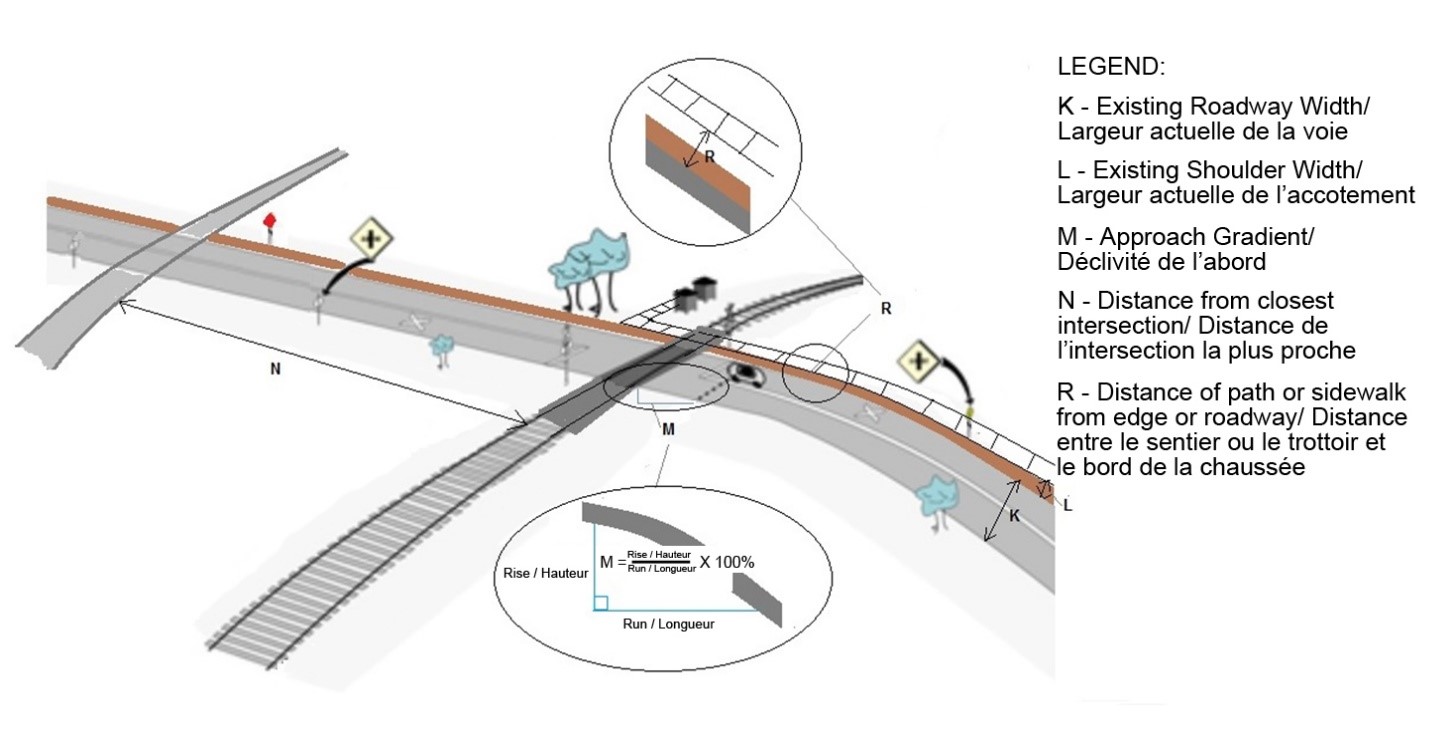
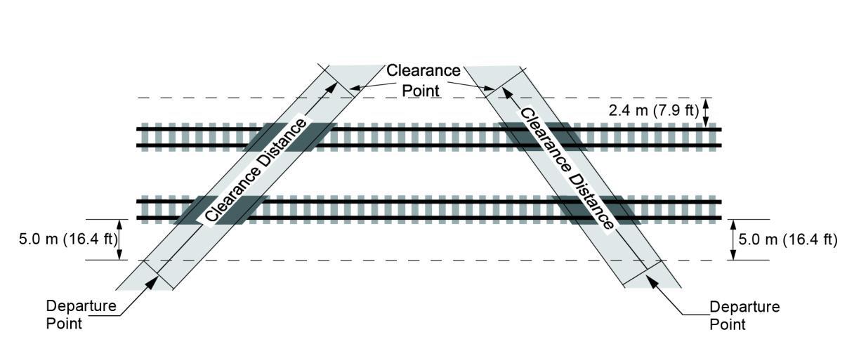
Information specific to the crossing to be completed by the Road Authority. 21. Total Number of Traffic Lanes: The total number of existing lanes traversing the crossing (e.g., total number of lanes in both directions at the crossing). 22. Annual Average Daily Traffic (AADT): The total number of motor vehicles that cross a grade crossing in a year divided by the number of days in that year. 23. Existing Roadway Width: Existing roadway width, in meters, of travelled lane measured from the outside lane edges. See Appendix A, Figure 1(K). 24. Grade Crossing Angle: Angle, in degrees, measured starting from the centerline axis of the Railway tracks to the centerline axis of the roadway. See Appendix A, Figure 2. 25. Roadway Approach Information: To complete this field, refer to the specifications set out in columns A, B and C of table 10-2 (Road Design Specifications) of the GCS to which the road approach corresponds, considering the characteristics set out for rural roads in table 10-3 of the GCS, or the characteristics set out for urban roads in table 10-4 of the GCS. http://www.tc.gc.ca/eng/railsafety/grade-crossings-standards-318.htm 26. Average Approach Gradient: Average slope (in percentage) of each corresponding road approach. The ‘road approach' means the part of the road, other than the crossing surface, that lies between the point that marks the start of the stopping sight distance and the point that marks the front of the design vehicle when it is past the Clearance Point. The Clearance Point is shown in Appendix A Figure 3. The approach gradient for a road approach is always measured in the same direction approaching the crossing from the start of the stopping sight distance. A positive (+) slope represents an ascending slope, and a negative (-) slope represents a descending slope. Approach 1 – Indicate the appropriate orientation / direction of traffic approach (e.g., Northbound (NB) or other) and the corresponding road approach gradient in the field provided. Approach 2 – Indicate the appropriate orientation / direction of traffic approach (e.g., Westbound (WB) or other) and the corresponding road approach gradient in the field provided. 27. Existing Shoulder Width: Average existing shoulder width, in meters, measured from the outside lane edge to the outside edge of shoulder. If no shoulder exists, the field can be left blank. See Appendix A, Figure 1(L). Approach 1 – Indicate the appropriate orientation / direction of traffic approach (e.g., Northbound (NB) or other) and the corresponding shoulder width in the fields provided. Approach 2 – Indicate the appropriate orientation / direction of traffic approach (e.g., Westbound (WB) or other) and the corresponding shoulder width in the fields provided. 28. Path or Sidewalk: Select whether a path and/or sidewalk exists, and whether it is designated for persons using assistive devices. |
|
SECTION 6 – Crossing User Details |
|
Information specific to the crossing to be completed by the Road Authority. 29. Design Vehicle: Establish what design vehicle is used for the road crossing. The design vehicle must correspond to one of the vehicles shown in Figures 1.2.4.1 to 1.2.4.11 of the Geometric Design Guide for Canadian Roads, published by the Transportation Association of Canada (September 1999), and the amendment dated January 2002. 30. Road Crossing Design Speed: (a) in the case of a new grade crossing, the motor vehicles speed used in the design of the grade crossing; or (b) in the case of an existing grade crossing, the motor vehicles speed that corresponds to the current design of the grade crossing. 31. Departure Time: Departure time of the Design Vehicle, based on the accepted Design Vehicle, in seconds, as calculated by Article 10.3 of the GCS. Please note that the gradient (one per approach) used in the calculation of the Departure Time is the average gradient over the Vehicle Travel Distance. The Vehicle Travel Distance is the distance from the rear of the design vehicle at the stopped position to the point that marks the front of the design vehicle when it is past the Clearance Point. 32. Stopping Sight Distance (SSD): The distance calculated in accordance with Article 7.2 of the GCS. 33. Advanced Activation Time: The time calculated for a Prepare to Stop at Railway Crossing, in accordance with Article 18.2 of the GCS. |
|
SECTION 7 – Interconnected Devices |
|
Information specific to the crossing to be completed by the Road Authority. 34. Interconnection Time: Select whether a warning system interconnected with nearby traffic signals exists at the crossing location. If ‘yes', the ‘interconnection time' must be provided, meaning the time for vehicles to clear the grade crossing before the arrival of railway equipment at the crossing surface in seconds. |
Appendix Figure G-1 Grade Crossing Details (Form Appendix A Figure 1)
Appendix Figure G-2 Grade Crossing Angle (Form Appendix A Figure 2)

Appendix Figure G-3 Grade Crossing Clearance Point (Form Appendix A Figure 3)
Appendix H - Sharing of Information Form Railway
In accordance with Transport Canada's Grade Crossings Regulations
This form may be used by the Railway when sharing information with aRoad Authorityfor the purpose of complying withsections 4 to 11 of the Grade Crossings Regulations (GCR). The Railway Sharing of Information Form Job Aidcan be referenced to complete the forms.
|
SECTION 1 – General |
||||||||||||
|---|---|---|---|---|---|---|---|---|---|---|---|---|
|
A. Railway Company: |
B. Date of Submission (yyyy/mm/dd): |
|||||||||||
|
C. Railway Company Contact Information |
||||||||||||
|
Name: |
Mailing Address: |
|||||||||||
|
|
|
|||||||||||
|
E-mail Address: |
||||||||||||
|
|
||||||||||||
|
Telephone Number: |
||||||||||||
|
|
||||||||||||
|
Additional Railway Company Contact Information (in case of emergency) |
||||||||||||
|
Name: |
Mailing Address: |
|||||||||||
|
|
|
|||||||||||
|
E-mail Address: |
||||||||||||
|
|
||||||||||||
|
Telephone Number: |
||||||||||||
|
|
||||||||||||
|
D. Road Authority: |
||||||||||||
|
Crossing Form |
Crossing No. _________of_________ |
|||||||||||
|
SECTION 2 - Grade Crossing Location (At least two [2] of the four [4] fields must be completed to identify the grade crossing location) |
||||||||||||
|
E. Railway Subdivision & Mileage |
1 |
|||||||||||
|
F. Latitude & Longitude |
2 |
|||||||||||
|
G. Roadway Name |
3 |
|||||||||||
|
H. City or Town Name |
4 |
|||||||||||
|
SECTION 3 – Reason(s) for sharing information with the Road Authority (Select all that apply and provide details below. Proceed to SECTION 6 if none of the following apply) |
||||||||||||
|
I. Information must be shared for existing public grade crossings no later than two years of the GCR coming into force. Ref. (GCR 4. (3)) |
||||||||||||
|
J. Receipt of a notice under section 3 of the Notice of Railway Works Regulations. Ref. (GCR 4. (2)) |
||||||||||||
|
K. A line of railway is added within the sightlines of the grade crossing and the sightlines must meet the requirements in section 20 of the GCR. Ref. (GCR 5 GCR28. (a)) |
||||||||||||
|
L. There is a change in the class of track referred to in column 1 of the table in Article 7.1.2 of the Grade Crossings Standards (GCS) when considering the maximum allowable operating speeds set out in column 2 or 3 of that table. Sightlines at the grade crossing must meet the requirements in section 20 of the GCR. Ref. (GCR 5 GCR28. (b)) |
||||||||||||
|
M. A new warning system is installed at a grade crossing and must meet the applicable standards set out in Articles 12 to 16 of the GCS. Ref. (GCR 5 GCR87. (1)) |
||||||||||||
|
N. A component of a warning system is modified or installed and must meet the applicable standards set out in Articles 12 and 16 of the GCS. Ref. (GCR 5 GCR87. (2)) |
||||||||||||
|
O. A new installation of a warning system, or the modification or installation of a component of a warning system which results from an increase in the railway design speed. The warning system or component must meet the applicable standards set out in Articles 12 and 16 of the GCS before the increase in the railway design speed takes effect. Ref. (GCR 5 GCR87. (3)) |
||||||||||||
|
Details with respect to the change(s) selected: |
||||||||||||
|
SECTION 4 – Railway Crossing Details |
||||||||||||
|
P. Number of Tracks |
|
|||||||||||
|
Q. Average Annual Daily Railway Movements |
|
|||||||||||
|
R. Railway Design Speed |
Freight trains (mph): |
|
Passenger trains (mph): |
|
||||||||
|
SECTION 5 – Railway Crossing Warning System |
||||||||||||
|
S. Crossing Warning System (Select all that apply) |
||||||||||||
|
None Crossbuck Flashing lights Bell Gates Cantilever Warning system(s) for path or sidewalk Other(s) ___________________________ |
||||||||||||
|
T. Stop Sign Present |
||||||||||||
|
Yes, on Railway Crossing sign |
No |
|||||||||||
|
U. Anti-Whistling Present |
||||||||||||
|
Yes Special Provision(s) (Optional field) ____________________________________ |
No |
|||||||||||
|
SECTION 6 – Notification of Other Changes (Select all that apply and provide details below) |
||||||||||||
|
V. Increase in the railway design speed at a public grade crossing. Ref. (GCR6) |
||||||||||||
|
New railway design speed (mph): |
|
|||||||||||
|
Date the new speed takes effect (yyyy/mm/dd): |
|
|||||||||||
|
W. Increase in the average annual daily railway movements by 50% or more and if the value is three [3] or more. Ref. (GCR8) |
||||||||||||
|
New average annual daily railway movements: |
|
|||||||||||
|
X. Whistling is no longer required at a grade crossing. Ref. (GCR9) |
||||||||||||
|
Date of change (yyyy/mm/dd): |
|
|||||||||||
|
Y. Transfer of a line of railway to another company. Ref. (GCR10) |
||||||||||||
|
Railway Company Name: |
|
|||||||||||
|
*/ Address: |
|
|||||||||||
|
Telephone Number: |
|
|||||||||||
|
E-mail Address: |
|
|||||||||||
|
Name of Contact Person: |
|
|||||||||||
|
Date of Transfer: |
|
|||||||||||
|
Details with respect to the change(s) selected: |
||||||||||||
Job Aid - Railway Sharing of Information Form
This Job Aid is to be used as a reference document when completing the Railway Sharing Of Information Form.
|
Railways are required to share safety-related information with the Road Authorities for all federally regulated crossings in their jurisdiction by November 28th, 2016. Additionally, it is the Railway's responsibility to provide notification of changes and share specific information related to these changes with the Road Authorities in accordance with the requirements of the Grade Crossings Regulations. The sharing of information will foster collaboration between the Railway Companies and Road Authorities responsible for the safety at grade crossings. The RAILWAY SHARING OF INFORMATION FORM may be used by the Railway to share information or to provide notification of changes concerning construction and operations. Once completed, the form should be sent to the appropriate Road Authority within the required timeframe indicated in the Grade Crossings Regulations. A courtesy copy may be sent to Transport Canada Rail Safety for their records. Mailing Address: Transport Canada Email: RailSafety@tc.gc.ca Fax: 613-990-7767 NOTE: As per section 108 of the GCR, a Railway must keep the most recent information provided to a Road Authority under sections 4 to 11 of the GCRand the most recent information received from a Road Authority under sections 12 to 18. COVER FORM To be completed and used as a general cover page to which all Crossing Forms associated with the same Road Authority can be attached. |
|
SECTION 1 – General |
|
General information to be completed by the Railway. All fields must be completed. A. Railway Company: Full name of the Railway responsible for the maintenance and/or construction at the crossing. B. Date of Submission: Date on which the form is sent. All information provided must be updated to reflect the actual conditions of the crossing on the date of submission. C. Railway Company Contact Information:
Note: The GCRrequires that contact information be provided for the purposes of information sharing (Section 4), planning maintenance (Section 102) and emergency notification (Section 103). While only one contact is required, Railways may wish to provide one contact for information sharing and planning and a separate contact for emergency notifications in the additional field provided. D. Road Authority: Name of appropriate Road Authority being notified. |
|
SECTION 2 – Grade Crossing Location |
|
At least two [2] of the four [4] fields must be completed to identify the grade crossing location. E. Railway Subdivision & Mileage: Full name of railway subdivision and railway mileage point rounded to two [2] decimal places used to identify the location of the crossing within the Railway's network. Example: Mile 102.91 Parry Sound Subdivision F. Latitude & Longitude: Latitude and longitude coordinates identifying the centre point of the crossing. The centre point can be defined as the intersection between the centerline axis of the railway tracks and the centerline axis of the roadway. G. Roadway Name: Full name representing the most updated and commonly known road name. Typically, the road name printed on the corresponding street sign. If a concession reference exists, this can also be provided. Example: Murphy Road also-known-as (a.k.a.) County Road 21 H. City or Town Name: Full name representing the City or Town in which the crossing is situated. Should the crossing not be situated in a City or Town, the common name of the Township, Village, or Hamlet can be entered. |
|
SECTION 3 – Reason(s) for Sharing Information with the Road Authority |
|
This section must be completed to identify the reason(s) the corresponding information in SECTIONS 4 & 5 of the Crossing Forms is being shared with the Road Authority. Check all that apply and include relevant details in the fields provided. Proceed to SECTION 6 (Notification of Other Changes) if none of the reasons in SECTION 3 apply. Note: If any of the changes from ([J] to [O]) are selected, notification in writing of the change(s) must be provided to the Road Authority no later than 60 days before the day on which the change begins. |
|
SECTION 4 – Railway Crossing Details |
|
Information specific to the crossing to be completed by the Railway. P. Number of Tracks: Total number of existing tracks going through the crossing. Q. Average Annual Daily Railway Movements: The total number of movements of engines, or engines coupled with railway equipment, across a grade crossing in a year, divided by the number of days in that year. R. Railway Design Speed: Defined as (a) in the case of a new grade crossing, the railway equipment speed used in the design of the grade crossing; or (b) in the case of an existing grade crossing, the railway equipment speed that corresponds to the current design of the grade crossing. |
|
SECTION 5 – Railway Crossing Warning System |
|
Information specific to the Railway Crossing Warning System(s) to be completed by the Railway. S. Crossing Warning System: Check all boxes that apply regarding the existing crossing warning system present at the grade crossing. The ‘Other' box may be selected to further describe other or additional crossing protection aspects relative to the Railway, such as additional flashing lights for nearby driveways, locked gates at spur lines, pre-emption, pedestrian gates, etc. T. Stop Sign Present: Establish whether a Stop Sign is installed on the same post as the Railway Crossing sign. U. Anti-Whistling Present: Establish whether anti-whistling exists at the crossing. ‘Special Provision(s)' can be specified to further describe any restrictions or details of the anti-whistling such as time period constraints. |
|
SECTION 6 – Notification of Other Changes |
|
This section must be completed to identify any changes that concern a public grade crossing which must be shared with the Road Authority in accordance with the requirements of sections 6 to 11 of the GCR. Include all relevant details of the change(s) in the fields provided. V. Increase in the railway design speed: When there is an increase in the railway design speed at a public grade crossing, the precise location of the grade crossing and the new railway design speed must be indicated in the form. Notification of an increase in the railway design speed must be given to the Road Authority in writing not later than 60 days before the day on which the increase takes effect. W. Increase to average annual daily movements: When the average annual daily railway movements increase by 50% or more relative to the previous value, and if the value is three [3] or more, notification of this change must be provided to the Road Authority. X. Whistling is no longer required at a grade crossing: If the use of a whistle is no longer required at a grade crossing, notification of this change must be given to the Road Authority in writing not later than 30 days after the day on which the change is made. Y. Transfer of a line of railway to another company: If a line of railway at a public grade crossing is transferred from one railway company to another, the railway company to which the line of railway is transferred must, within seven [7] days after the day on which the transfer takes effect, provide the Road Authority with the name, address, telephone number and email address of a contact person. |
Appendix I - Canadian Grade Crossing Detailed Safety Assessment Field Guide
Under Development
Appendix J - Testing Requirements (Railway)
Maintenance, tests, and repair work that may interfere with safe operation of trains must not be started until train movements have been fully protected. Temporary repairs or adjustments, when required, must be made in such a manner that safety of train operation will not be impaired. When a repair, adjustment, change, or replacement is made, tests must be carried out immediately to verify that the apparatus functions as intended. Proper instruments/equipment must be used to test the apparatus, and the use of such instruments or equipment must not create unsafe conditions.
In the event severe weather or other environmental conditions may have affected the operation of the warning system or its components, the warning system and its components must be inspected within a reasonable period to verify that they are working properly. (GCR 94(3)).
To verify that the warning system functions as intended, tests are to be conducted at the intervals specified in Part D of this document and tables 17-1, 17-2, and 20-1 of the Grade Crossings Standards (GCS), reproduced herein. Each test prescribed must be conducted at least once within the prescribed frequency, as defined in columns 2 and 3 of Table 17-1.
To facilitate troubleshooting and maintenance, each wire in all housings, including switch circuit controllers and terminal or junction boxes, must be tagged at each terminal, and its identification must not interfere with moving parts of the warning system. Identification tags/labels must be made of Insulating materials. This requirement does not apply to light units or wiring that is an integral part of solid-state equipment.
Because of the potential for an inspection and/or test to create a condition that could compromise the safety of railway operations, it is recommended that temporary protection measures be put in place before beginning any of the inspections/tests enumerated below. Should an inspection or test pose an actual threat to the safety of railway operations, protection measures must be applied.
Note: This is a regulatory requirement for all new grade crossings with a warning system, as well as to existing grade crossings, and when a change is made to components of their warning system (GCR44, 55, 87(2)). (SeeArticle 2 for more information on amendments to the GCR timelines)
Any issues noted during any of these inspection items must be reported to the Rail Traffic Controller immediately, in accordance with CROR 103.1 (h).
The results of the inspections and tests specified herein, and all other inspections and tests that may be required, must be recorded as per section 109 of the GCR.
Appendix K - Testing Requirements (Road Authority)
Note: The items listed below are within Table 20-1 of the Grade Crossing Standards (GCS).
Item 1 - Prepare to Stop at Railway Crossing sign: for visibility of light units
Frequency:
Annually.
Purpose
To verify that the electrical Prepare to Stop at Railway Crossing sign is installed in accordance with the Manual of Uniform Traffic Control Devices for Canada and that the signs light units are visible to road users approaching the grade crossing.
Process
Because of the potential for this inspection to trigger a condition that could compromise the safety of railway operations, it is recommended that temporary protection measures be put in place before beginning the tests.
Verify that the Prepare to Stop at Railway Crossing sign is installed in accordance with Article A1.6 of the Manual of Uniform Traffic Control Devices for Canada.
Verify that the Prepare to Stop at Railway Crossing sign and its light units can be seen by road users approaching the stopping sight distance (SSD) point at the road design speed.
Item 2 - Traffic signals installed at a grade crossing in lieu of a warning system: for cleanliness, visibility of signal heads, and physical damage
Frequency:
Annually.
Purpose
To ensure that traffic signals installed at a grade crossing in lieu of a warning system are clean, visible, and free of physical damage.
Process
Because of the potential for this inspection to trigger a condition that could compromise the safety of railway operations, it is recommended that temporary protection measures be put in place before beginning the inspection.
Verify that all traffic signals installed at the grade crossing in lieu of a warning system are clean and free of dust, grease, and dirt.
Verify that they are visible to the road users within the SSD when illuminated and that they are aligned as per to the coordinates designed for each traffic signal.
Verify that they are free of defects, damage, and faded or rusty parts.
Item 3 - Traffic signal interconnection activation and operation with warning systems
Frequency:
Annually.
Note: This inspection should be conducted jointly with the railway authority.
Purpose
To ensure that the control circuits operate as designed and provide adequate warning be means of activating the traffic signals when railway equipment is detected.
Process
Because of the potential for this inspection to trigger a condition that could compromise the safety of railway operations, it is recommended that temporary protection measures be put in place before beginning the inspection.
Information on the parameters for operating the traffic control device must be on site and available to the road authority for inspection, testing and maintenance purposes (GCR 96(3)).
Verify that the recorded pre-emption times or synchronization (for the crossing) is in accordance with the design plans. Perform a test, ideally together with the railway, to confirm that the interconnection functions as designed (traffic controller test switch, actual train move, etc.). All phases of the interconnection should be tested as per the worst-case scenario.
When the Railway Crossing warning system is activated, the interconnected traffic signals must prevent road traffic from travelling over the Railway Crossing before railway equipment arrives at the crossing surface. The traffic signals must not give road users any indication to proceed towards the interconnected grade crossing once the automatic warning system has been activated.
Take into consideration all possible traffic movement, from all directions, and verify that the traffic lights give road users no indication to travel over the grade crossing before the arrival of a train at the crossing surface once the warning system has been activated.
If the site is equipped for such, verify that a minimum of four hours of battery backup up is provided.
Item 4 - Prepare to Stop at Railway Crossing sign activation and operation
Frequency:
Annually.
Note: This inspection should be conducted jointly with the railway authority.
Purpose
To ensure that the control circuits operate as designed and provide adequate warning by activating the Prepare to Stop at Railway Crossing sign when railway equipment is detected.
Process
Because of the potential for this inspection to trigger a condition that could compromise the safety of railway operations, it is recommended that temporary protection measures be put in place before beginning the inspection.
Where Prepare to Stop at Railway Crossing signs are installed and interconnected with a grade crossing warning system, verify that the advance activation time is the greater of the time it takes a vehicle travelling at the road crossing design speed to pass a deactivated Prepare to Stop at Railway Crossing sign and to:
- clear the grade crossing before the arrival of railway equipment at the crossing surface, where there is a warning system without gates; or
- clear the grade crossing before the gate arms start to descend, where there is a warning system with gates.
Perform a test to confirm that the interconnection functions as designed by simulating an operation (traffic controller test switch, actual train movement, etc.).
During the simulations, verify that the light units of the Prepare to Stop at Railway Crossing sign are illuminated and flashing in unison when activated.
If the site is equipped for such, verify that a minimum of four hours of battery backup up is provided.
Appendix L - Guideline for Inspecting and Testing Pre-Emption of Interconnected Traffic Control Signals and Grade Crossing Warning Systems
Introduction
This guide was developed in consultation with Canadian stakeholders including members of the railway industry, Transport Canada, municipalities, road authorities, related professional associations, and federal and provincial government agencies concerned with public safety at grade crossings.
In the past, actions were taken that adversely impacted public safety with interconnected traffic signals and grade crossing warning systems. As a result, the ITE and AREMA got together and jointly addressed the problems encountered. There is now a new FHWA produced MUTCD chapter 8 that now addresses design. AREMA standards have now been modified to reflect these requirements.
This guideline is intended for railway and road authority employees or contractors assigned to the inspection, maintenance, repair, and the testing of grade crossings warning systems and traffic control signals that are interconnected for the purpose of pre-emption of traffic control signals, or the activation of Prepare to Stop at Railway Crossing sign(s) (WB-6) beacon lights.
The procedures and forms recommended in this guide are provided solely as a guide and should not be quoted or considered as legal authority.
This guide is not intended to replace existing safety procedures or forms in use by the railway or road authority that may be more stringent; and should not considered to be a design document.
Use of this guide is intended to promote a regular joint railway/road authority inspection or test program for interconnected traffic control locations as well as improve communication between the responsible authorities.
Transport Canada welcomes further comments and input into future revisions of this guidance document as part of the ongoing improvement process with this publication.
Guidance
When interconnected, the grade crossing warning system and the traffic control signals operate in a very precise fashion and should be regarded as one system for purpose of “railway activated” pre-emption. For this reason, the sample checklists, site information and joint inspection record form are available in Appendix L-1 of this document. The form may be personalized for your record keeping and should be kept available at each interconnected system location for use as needed.
Railway and Road Authority Sample Checklist
The Sample Checklists found in Articles 1 and 2 below of these appendices provide a systematic method of verifying interconnected systems stated design features. This is for the use of railway and road authority employees and contractors assigned to inspect, maintain, or test grade crossing warning systems interconnected with roadway traffic control signals. Additional checks may be deemed necessary by your responsible engineering managers to ensure proper functioning of interconnected systems.
Note: Any changes to railway or road traffic conditions discovered during the performance of these checks or other regularly scheduled inspections must be reported to the other party. The relevance of these observed changes may trigger an engineering safety evaluation of the site. Examples of this are changes to railway operation or speed; changes to design vehicle, road crossing design speed, increase in average annual daily traffic; spotting vehicles queuing onto crossing surface area; and vehicles having difficulty stopping safely when a train approaches and activates the warning system.
Site Information and Joint Inspection Record Form
The sample site information and joint inspection record form found in Appendix L-1 provides a location for recording site-specific information including contact persons, crossing and intersection coordinates, railway control circuit features, and design timing parameters. No maintenance employee is authorized to make changes to the system settings without completion of an engineering joint safety site study. The bottom section of the form allows documentation of joint inspection due date and should be completed by the employees assigned to conduct the joint inspection and tests.
Warning Labels
The use of weather resistant, self-adhesive, florescent labels to help identify these unique interconnected systems are to be installed in the traffic control cabinet and the railroad warning system enclosure (bungalows or cases). This information could be critical during a system failure or when a manual override of the traffic control system by local enforcement agencies or rail and road supervisory and maintenance personnel is needed. The labels affixed at each signal control housing, should be clearly visible.
In cases where the Railway Crossing operation test feature also pre-empts the traffic signal, another label affixed near this test feature is required. This will remind or inform the railway employee performing the test they will cause activation of the pre-emption action at the traffic signals when testing.
Railway Safety Act and You
The Railway Safety Act (RSA) has requirements with respect to all engineering work relating to railway works.
-
Subsection 11(1) and 11(2) of the RSA states:
“All work relating to railway works — including, but not limited to, design, construction, evaluation, maintenance and alteration — must be done in accordance with sound engineering principles.”
And
“All engineering work relating to railway works must be approved by a professional engineer”
Employees responsible for the maintenance of these systems should not make any changes or modifications without prior authorization by a professional engineer. Any changes on one system may have serious consequence on the other, and the impact on both systems must be carefully assessed.
-
Subsection 41 (1) of the RSA, states:
Every person who contravenes a provision of this Act is guilty of an offence and liable:
- on conviction on indictment,
- in the case of a corporation, to a fine not exceeding one million dollars, and
- in the case of an individual, to a fine not exceeding fifty thousand dollars or to imprisonment for a term not exceeding one year, or to both.
- on summary conviction,
- in the case of a corporation, to a fine not exceeding five hundred thousand dollars, and
- in the case of an individual, to a fine not exceeding twenty-five thousand dollars or to imprisonment for a term not exceeding six months, or to both.
- on conviction on indictment,
If you would like more information regarding the application of Section 11 of the RSA, please contact Transport Canada Rail Safety at the contact info provided in Appendix F of the Grade Crossing Handbook.
Article 1 - Railway “Inspection and Tests Sample Checklist”
- Regular Inspection and Test
- Ensure the design parameters are recorded on the “Site Information and Joint Inspection Record Form” (see Appendix L-1).
- Activate grade crossing warning system.
- Confirm that the pre-emption signal activates the traffic signals.
- If applicable, confirm advance pre-emption or activation of traffic signal (flashing signal, turn restrictions etc.).
- Ensure all warning labels are clearly visible and legible.
- If due, arrange the upcoming Joint Railway/Road Authority Scheduled Inspection and Test; and
- Report any railway, road traffic or physical surroundings condition changes (additions resulting in line of site obstructions etc.).
- Joint (Railway/Road Authority) Inspection and Test
- Verify Timing Design Parameters listed on the “Site Information and Joint Inspection Record Form” (see Appendix L-1).
- Confirm interconnection circuit wires are free of grounds or foreign currents and the system fails in the safe mode.
- Identify if special features are included and that they function as designed (e.g.: supervisory circuit, power failure monitoring circuit).
- Activate grade crossing warning system and confirm pre-emption activation of traffic signals during all phases of the traffic controller unit operation.
- Repeat previous step for multiple track locations including any advance pre-emption circuits; and
- Record joint inspection and test date as well as the next scheduled date on the Site Information and Joint Inspection Record Form
Article 2 - Road Authority “Inspection and Tests Sample Checklist”
- Regular Inspection and Test
- Ensure the timing design parameters are recorded on the “Site Information and Joint Inspection Record Form”.
- Simulate the pre-emption signal input from grade crossing warning system while confirming the railway interconnect is connected to the highest priority control unit input.
- Confirm pre-emption activation of traffic signals including any associated pre-signals or active signs etc. and that the clear-out phase on the control unit cannot reset or resume its normal operation until the gates have returned to the vertical position or the Railway Crossing warning system is no longer operating.
- Confirm the standby battery power “if applicable”, operates as designed.
- Ensure all warning labels are clearly visible and legible.
- If required, arrange upcoming Joint Railway/Road Authority Scheduled Inspection and test; and report any roadway, rail traffic, or physical surroundings condition changes that may affect the road user's line of site visibility.
- Joint (Railway/Road Authority) Inspection and Test
- Confirm Timing Design Parameters on the “Site Information and Joint Inspection Record Form” are correct and are operating as designed in the field.
- Confirm interconnection circuit wires are free of grounds or foreign currents and the system fails in the safe mode.
- Confirm the pre-emption signal from the railway is connected to highest priority pre- emption input.
- Identify if special features are included and function as designed (e.g.: interconnect supervisory circuit, power failure monitoring circuit).
- Activate grade crossing warning system (railway action) and confirm pre-emption activation of traffic signals responds during all phases of the traffic controller unit operation.
- Confirm pre-emption restarts after a CU time-out sequence (second or stopped and restarted train scenario) note: when using gates this time out sequence should not be possible unless gate arms have been activated up resetting the CU, “this is sometimes referred to as traffic signal controller re-service”.
- Ensure pedestrian clear-out time matches the design timing.
- When applicable, ensure the active “Prepare-to-Stop-at-Railway-Crossing Sign (WB-6)” delayed beacon turn-off time; and
- Record joint inspection and test date as well as the next scheduled date on both the railway and road authority Site Information and Joint Inspection Record Forms.
Definitions
Note: Common definitions are used in this guide and are adopted by the ITE. In the US the Federal Highway Administration (FHWA) produces their own definitions through the Manual of Uniform Traffic Control Devices for Canada (MUTCDC).
Advance Pre-emption / Advance Pre-emption Time (APT)
Notification of an approaching train is forwarded to the highway traffic signal controller by railroad equipment for a period prior to activating the railroad active warning system. This period is the difference in the Maximum Pre-emption Time required for highway traffic signal operation and the Minimum Warning Time needed for railroad operation. (Note: common definitions have been adopted by AREMA and the ITE and are used in the US FHWA version of the MUTCD)
Advance Activation Time of the Prepare to Stop at Railway Crossing Sign (WB-6)
The time specified by the road authority to provide advance notification of an approaching train before the activation of the grade crossing warning system. “See advance pre-emption time.” (TC)
Approach Timing (prescribed warning time)
Prescribed Warning Time (Minimum Warning Time) – For through train movements, Prescribed Warning Time (Minimum Warning Time) is the least amount of time a warning system shall operate prior to the arrival of a train at a grade crossing.
Beacon
This is a signal face (light) with one or more sections that operates in the flashing mode. (ITE)
Clear Storage Distance (CSD)
The distance available for vehicle storage measured between 2.4 meters from the rail nearest the intersection to the intersection stop line or the normal stopping point of the roadway.
Control Unit (CU)
A part of a traffic signal controller assembly that is devoted to the selection and timing of signal phases. (ITE) Note: These come in several versions with different characteristics regarding identifying the railway priority input(s). (ITE)
Delayed Turnoff of Prepare to Stop at Railway Crossing Sign (WB-6)
This is a delay in the turn off the advance warning sign beacons and is intended to reduce the speed of approaching vehicles thus allowing the crossing area to safely clear out of previously stored traffic after the passage of a train. (TAC)
Grade Crossing
A road crossing at grade, or two or more road crossings at grade where the lines of railway are not separated by more than 30 m.
Interconnected Signals
These are traffic signals that are connected by some means for the purpose of establishing a definite timing relationship. (ITE)
Interconnection
This is the electrical connection between the grade crossing warning system and the traffic signal controller for the purpose of pre-emption. This may be a “Vital Serial” wire or wireless connection utilizing isolated vital serial data circuit(s) or a hard wire interconnection circuit. Vital serial connections are designed using fail-safe design principals. (ITE)
Institute of Transportation Engineers (ITE)
This organization prints the US MUCTD and has a joint committee with AREMA to ensure there are common definitions used when these systems are interconnected. This guide incorporates the ITE definitions.
Manual of Uniform Traffic Control Devices for Canada (MUTCD-C)
Manual of Uniform Traffic Control Devices for Canada and is managed by the Transportation Association of Canada. You can find more information at their website.
Manual of Uniform Traffic Control Devices US (MUTCD)
The MUTCD for the USA is a product of the (FHWA) and covers all aspects of traffic design including crossing protection interconnection in section 8. The manual may be ordered from their website or may be downloaded via the FRA website.
Minimum Warning Time (through train movements)
The least amount of time a grade crossing warning system shall operate prior to the arrival of railway equipment at the grade crossing. (ITE)
Motion Sensing
Directional Logic System with additional capability to differentiate between moving trains (Greater than 2 mph) and stopped trains (Less Than 2 mph); and ability to provide direction of motion.
Pre-emption
The transfer of normal operation of road traffic control signals to a special control mode. (ITE)
Note: The need for pre-emption, type of pre-emption and time interval for any advance pre-emption shall be determined by the road authority having jurisdictional authority.
Pre-Signal
This is a supplementary traffic signal that is part of the traffic control signal system and is controlled by the road intersection CU. It is normally placed in a position that controls road traffic approaching the grade crossing warning system and the intersection. (ITE)
Prepare to Stop at Railway Crossing Sign (WB-6)
The active Prepare to Stop at Railway Crossing Sign Indicates to drivers in advance of a Railway Crossing warning system that there is a high probability of having to stop for the grade crossing warning system ahead. The primary function is to reduce dilemma zone incidents. (MUTCD-C)
Queue Clearance Time (QCT)
The time required for the design vehicle of maximum length stopped just inside the clearance distance to start up and move through and clear the entire clearance distance.
Railway Safety Act (RSA)
This is an Act of the Parliament of Canada, which applies in respect of transport by federal railways to all persons, railway companies and railways within the legislative authority of Parliament. You can find a copy of the RSA here.
Right-of-way Transfer Time (RWTT)
The maximum amount of time needed for the worst-case condition, prior to display of the track clearance green interval. This includes any railway or highway traffic signal control equipment time to react to a pre-emption call, and any traffic control signal green, pedestrian walk and clearance, yellow change, and red clearance intervals for conflicting traffic.
Separation time
The maximum amount of time needed for the worst-case condition, prior to display of the track clearance green interval. This includes any railway or highway traffic signal control equipment time to react to a pre-emption call, and any traffic control signal green, pedestrian walk and clearance, yellow change, and red clearance intervals for conflicting traffic.
Simultaneous Pre-emption
Notification of an approaching train is forwarded to the highway traffic signal controller unit or assembly and railroad active warning devices at the same time. (ITE) Test and inspections:
This means to inspect certain components, and to subject them to specified electrical and/or mechanical tests to verify their proper operation, timing, and are required to be completed within the minimum frequencies prescribed in table 17-1, table 17-2 and table 20-1 of the Grade Crossings Standards as required by section 95 and 96 of the Grade Crossings Regulations
Traffic Signal Controller Re-service
This is when the pre-emption signal is re-established after an immediate prior activation as in a second train or a stop and restart scenario. (ITE)
Transport Canada (TC)
Transport Canada is the federal government department responsible for most of the transportation policies, programs and goals set by the government of Canada.
Vital Serial
Vital serial communication connections are designed using fail-safe design principals. A break or unacceptable change in the data stream acts the same as a broken or shorted wire in a conventional wire based interconnected fail-safe designed system. (ITE)
Warning System
An automated system, other than and interconnected traffic signal, that Indicates the approach or presence of railway equipment at a grade crossing and that is composed of any combination of light units, bells, gates, operating mechanisms, and circuits.
WB-6
This is the TAC (MUTCD-C for Canada) identifier used for active Prepare to Stop at Railway Crossing Signs. The old name used for this was Active Advance Warning Sign and this reference may still be used in some areas of North America. (TAC)
Appendix L-1
Site Information and Joint Inspection Record Form
For
Interconnected Grade Crossing Warning Systems with Traffic Control Signals
ATTENTION:
DO NOT MODIFY the pre-emption design without written joint approval from the railway and the road authority engineers responsible for safety at this location.
Date of joint inspection___________________ Date of Road Authority inspection________________
Railway Co. ______________________________ Subdivision ______________________________
Contact person ____________________________ Subdivision mileage ______________________
Phone no _____-_______-________________ Email address ___________________@__________
Railway emergency call number _____-_____-_____________
Transport Canada Crossing Inventory No. ______________
Road Authority _____________________________ Road intersections __________& ___________
Contact person ______________________________ Email address _____________@___________
City _____________________________________ Phone No _______-_______-________________
Province _________________________________ R. A. Identifier ____________________________
Road Authority (R.A.) emergency call number _____-_____-____________
Grade Crossing Warning System Type and Timing Control Circuit Settings:
Constant warning approach timing: ____ Fixed distance approach timing: ____ Motion sensing: ____
Does test switch feature deactivate pre-emption of traffic signals: Yes _____ No ______.
Does test switch feature activate pre-emption of traffic signals: Yes _____ No ______.
Grade crossing warning system warning time _________________________ seconds.
Advance Pre-emption Time (APT) if required by the Road Authority is _____ seconds in order to provide the total required Pre-emption time of ________seconds to the traffic signal controller.
Traffic Signal Pre-emption Activation Timing Settings and Control Circuit Type:
Controller unit type (specify): _________________________________________________________
Total Traffic controller pre-emption activation warning time required prior to train arriving at crossing is ______seconds. Note: This time is greater than the crossing activation time above if the railway is requested to provide advance pre-emption (railway term) due to their normal approach time being insufficient for road authority timing purposes. Delayed WB-6 beacon turn off time as specified by the Road Authority is ____ seconds. See Guide definitions for time setting explanations and sample timeline.
Interconnection circuit: Level: ____volts, Type (check): AC ___, DC ___ or Vital Serial ____
Next Joint Inspection Due: _____/____/_____ (sign below when inspection completed)
MM / DD / YYYY/ TT: TT | Railway Contact Name | Road Authority Contact Name
_____/____/_____/___:____ |___________________________|______________________________
(Print names) _________________________________________|______________________________
Appendix L-2
Recommended warning labels (Florescent orange or yellow background with black letters).
WARNING
THIS LOCATION IS
INTERCONNECTED WITH THE
GRADE CROSSING WARNING SYSTEM
Place this label at Traffic Signal Controller Housing location
Recommended warning labels (Florescent orange or yellow background with black letters).
WARNING
THIS LOCATION IS
INTERCONNECTED
WITH THE TRAFFIC CONTROL
SIGNALS
Place this label at the Railway Crossing Warning System Housing
WARNING
Keep the crossing warning test or flagging operation time short.
Activation of the Grade Crossing Warning System
Will affect the interconnected Traffic Control Signals.
Extended operation may require flagging of road traffic.
Place this label at the railway test location when applicable
Appendix M - Supplemental Engineering Design Guidance for Vulnerable Road Users at Grade Crossings
Terminology
Terms used in this guidance material are defined within Article 1 of this Grade Crossings Handbook.
Introduction
The Grade Crossings Regulations (GCR) and associated Grade Crossings Standards (GCS) came into effect on November 28th, 2014. The GCR aims to improve safety at grade crossings by setting comprehensive and enforceable safety standards for both new and existing grade crossings in Canada. The GCR clearly defines the roles and responsibilities of railway companies, road authorities and private authorities and requires that railway companies and road authorities share key safety-related information with each other. Subsection 12(1) of the GCR indicates that road authorities are required to determine if the grade crossing includes a sidewalk, path, or trail, and if so, whether the sidewalk, path or trail has been designated for use by persons using assistive devices.
In May 2018, Transport Canada (TC) committed to the development of supplemental engineering guidance to improve safety of grade crossings designed for Vulnerable Road Users (VRU) including persons using assistive devices. This commitment was made in response to a recommendation from the Transportation Safety Board of Canada (TSB) following the fatal collision involving a person using a wheelchair at a grade crossing in Moncton, New Brunswick on July 27, 2016. The full TSB investigation report can be found here.
In 2018, TC conducted a literature review and analyzed publicly available information on VRU treatment options available at grade crossings. The term VRU is defined within the transportation industry as pedestrians, cyclists or persons using assistive devices. VRUs are at greater risk of injury when involved in a collision due to the lack of protection they have from traffic. In Canada, since 2016, there have been two reported fatal collisions at grade crossings involving persons using assistive devices.
This document provides guidance on the relevant regulatory requirements and best practices regarding assessing the level of activities of Vulnerable Road Users (VRUs) at grade crossings, strategies in risk reduction, and improving crossing safety for VRUs.
Vulnerable Road User (VRU) Level of Activity Assessment
Grade crossings present various challenges to VRUs. For those that use a wheelchair, scooter or other mobility device, the mobility constraint at a grade crossing might be associated with apprehension and hesitant behaviour, especially at unfamiliar grade crossings. Flangeway gaps can present significant trip and entrapment risks, particularly for those using devices such as wheelchairs, wheeled walkers, strollers and walking canesFootnote 11. For wheelchair users, especially those in manual wheelchairs, the primary concern is getting a caster wheel stuck in one of the gaps over the crossing (i.e., a flangeway gap or any wider gaps between the surface and panels).
Existing sidewalks, paths, or trails leading to a grade crossing must meet the GCR, and the GCS. Other supplemental guiding principles are also provided in this Grade Crossings Handbook, the Manual of Uniform Traffic Control Devices for Canada, and Geometric Design Guide for Canadian Roads.
|
Parameter |
Assessment |
|---|---|
|
Crossing Volume* |
Number of assistive device users, pedestrians, and cyclists (low, moderate, high) Number of assistive device users, pedestrians, and cyclists of neighbouring roadway if crossing count is not available |
|
Pedestrian/Cyclist Facilities |
Presence of pedestrian facilities: sidewalks or pathways/bicycle facilities/multiuse pathways Evidence of crossings activities (e.g., dirt path leading to tracks) |
|
Neighbouring land use |
Road classification: urban or rural Presence of schools, parks/playgrounds, shopping centers, plazas, recreational centers, libraries, arenas, etc. Adjacent land use (e.g., major attractions on one or both sides of the grade crossing that would encourage users to cross at that location) |
Appendix Table M-1 provides a list of parameters to consider when assessing the level of activity at a grade crossing. These will serve to assess the needs of all potential users and to consider them in the design and maintenance of grade crossings. This assessment is typically collected by the responsible road authority for the grade crossing.
Assistive Device Users, Pedestrians and Cyclists Crossing Volume Activity Levels
Low: No presence of sidewalks, paths, or trails. No known use by vulnerable road users. Adjacent land use is rural/vacant, agricultural, or industrial with no sidewalks or pathways.
Moderate: Moderate use of crossing by vulnerable road users. Urban area and neighbouring land use is residential/commercial.
High: High crossing volumes. Significant attractions near the crossing (e.g., retirement residences, stadiums, schools, shopping malls). Clear evidence of vulnerable road users using the crossing on a regular basis.Footnote 12
Crossing Volume
Direct observation is the ideal means to assess how a crossing is used and by whom. Typically, this would be a standard eight-hour count that includes the peak periods in the morning, at mid-day, and in the afternoon (like vehicle counts). However, there may be considerable activity during other time periods due to the grade crossing's proximity to areas such as entertainment and recreation centres. As such, volume counts may be required outside of the standard eight-hour count period.
Crossing volume data should be classified by type, namely pedestrians, cyclists and persons using an assistive device. It may also be useful to further break down collected information by the age group of individuals, such as children, adults, and elderly.
Pedestrian/Cyclist Facilities
If grade crossing usage count is not available, the presence of existing facilities (e.g., sidewalk, bicycle lane, multi-use pathway) leading to the grade crossing will provide an indication of the likelihood of the presence of VRUs.
Neighbouring Land Use
Urban areas are expected to have a higher number of assistive device users, pedestrians, and cyclists than in rural areas. Attention should be given to major attractions or other public facilities, such as schools and shopping malls, where crossing activity can be expected to be high. Consideration should also be given to nighttime attractions located in the vicinity of the crossing, such as night clubs, theatres, restaurants, etc.
Design Options and Considerations
There are several engineering designs options that improve grade crossing safety. For example, signage and warning systems at grade crossings provide users with a variety of visual and audible cues to assist them with crossing safely. Engineering designs should also consider disabled persons who may have added challenges crossing safely depending on the physical characteristics of the crossing, such as the structure, gradient, and track exposureFootnote 13. The following engineering design options are applicable to typical grade crossings (provides a quick reference of typical design considerations for grade crossings to reduce site specific risks). Other measures can be considered, such as providing a grade separated crossing or offer alternative access (i.e., different location) to cross the tracks safely. For exceptional cases, consider having an evaluation conducted by practitioners.
Warning Signs
Warning signs caution users of hazards (e.g., skewed crossing, second train/track) or direct users to take a particular action (e.g., look both ways, do not cross here). Signs must not restrict the mobility of persons using assistive devices and must not restrict sightlines or the visibility of the warning systems at the grade crossing. Signs may lead to a moderate increase in comprehension levels.
For additional guidance refer to figures in Article 8 of this Grade Crossings Handbook.
Pavement Markings
Pavement markings define sidewalks and pathways leading to and across the crossing surface and indicate the desired location to stop while waiting for the approaching train. These markings may lead to a moderate increase in comprehension levels.
For additional guidance refer to figures in Article 8.8 of this Grade Crossings Handbook.
Surface Treatments
Surface treatments are visually contrasting materials, such as tactile walking surface indicators and flangeway gap fillers. They are expected to have a moderately positive impact on accessibility, particularly among those with a visual impairment and persons using assistive devices. Pedestrians with a visual impairment may find it difficult to identify that they are approaching a crossing because many of the cues are visual. Tactile surfaces in advance of the crossing provide visually impaired pedestrians with a reliable, recognisable indication that they are approaching a hazard.
Furthermore, flangeway gap fillers are designed to reduce the risk of small wheels or objects getting stuck in the flangeway gap and provide a smooth and continuous crossing surface. However, at the time of publication, the Canadian freight rail sector has limited experience with flangeway gap fillers; therefore, additional research may be warranted.
Barriers
Barriers, such as fencing and “Z” barriers or maze barriers, are designed to guide the crossing users to cross at a desired location. However, unless carefully designed, fencing and “Z” barriers may have a negative impact on accessibility. Persons using assistive devices and those with visual impairments may find them difficult to navigate. Barriers should be designed with consideration to the turning radii of assistive devices. Barriers may lead to a moderate increase in comprehension levels, as well as encourage the crossing users to look in the direction in which trains may be approaching.
For additional guidance refer to Article 26 of this Grade Crossings Handbook.
Refuge Area
The refuge area is provided to crossing users to wait while a train passes in advance of the stop line or tactile walking surface indicator. Incorporate standards and best practices in the design of the refuge area and ensure it is accessible and clearly identified for all grade crossing users, including assistive device users, pedestrians, and cyclists.
Active Systems with an auditory or visual warning system
Active systems with an auditory or visual warning system activate when a train approaches or occupies the crossing. This includes second train event warning systems. In an active warning system with gates, a gate is closed or lowered when a train is approaching or occupying the crossing. These systems would have a positive impact on safety, as well as accessibility because they provide assistance to those with auditory or visual impairments.
Grade Crossing Illumination
Grade crossing illumination benefit all users by providing increased visibility of the area and surrounding environment along the crossing approach and its surface in low-light or nighttime conditions.
|
Pedestrian Category |
Design Considerations Expected to Reduce Site Risk |
|---|---|
|
Automatic gates covering sidewalks/gate skirts [A, B, C, D] Active system (auditory/visual) [A, B, C, D] Signs to draw attention to the crossing as per MUTCDC and GCS and Grade Crossings Handbook (specifications in terms of location, height, visibility, ability to clearly convey the message etc.) [A, B, D] Barriers and guide fencing [A, B, C, D] Adequate illumination of the crossing and approaches [A, B, D] Signs advising train speed [A, B, D] Pavement marking as per MUTCDC (Defining and/or painting the approaches and across the tracks with edge lines) [A, B, D] Flangeway fillers [A, B, C] Tactile walking surface indicator [A, C] Visually contrasting pavement marking [A, B, C, D] |
Other Reference Material
As with all aspects of geometric design, engineering judgement is necessary when assessing the range of design options presented in this guideline. The best engineering practice is to design grade crossings in an integrated approach by considering the needs of all VRUs. In other words, in urban areas or where the presence of persons using assistive devices, pedestrians and/or cyclists may be high, transportation practitioners should ensure that the design of the grade crossing considers engineering standards and best practices and guidelines. It is recommended to consider direct observation for existing grade crossings in urban areas with sidewalks, paths, or trails. For new grade crossings, assumptions can be made based on plans for future developments (e.g., urban densification estimates are an indication of more sidewalks).
The following figures provide additional guidance on the dimension/operating envelope of pedestrians, which should be integrated in the design of facilities for all pedestrians. Design specifications, operating space, and dimensions are outlined in Section 6.2 of the Geometric Design Guide for Canadian Roads.
Appendix Figure M-1 Typical Pedestrian Dimensions
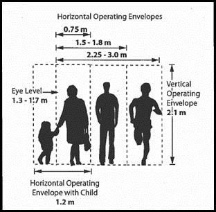
Source: Transportation Association of Canada (TAC), 2017, Geometric Design Guide for Canadian Roads
Appendix Figure M-2 Horizontal Operating Envelope for a person with a Service Animal
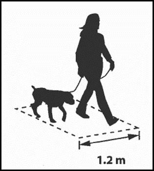
Source: Transportation Association of Canada (TAC), 2017, Geometric Design Guide for Canadian Roads, Chapter 6-Pedestrian Integrated Design
Appendix Figure M-3 Wheelchair User Dimensions
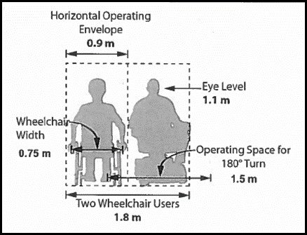
Source: Transportation Association of Canada (TAC), 2017, Geometric Design Guide for Canadian Roads, Chapter 6-Pedestrian Integrated Design
Appendix Figure M-4 Sidewalk design to optimize the railway crossing angle so that pedestrians can cross at a 90-degrees angle
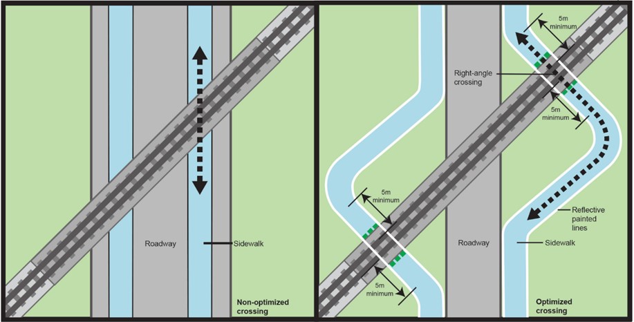
Source: Transportation Safety Board (TSB) Report R16M0026, July 2016, Railway Investigation Report Figure14: Sidewalk design to optimize the railway crossing angle so that pedestrians can cross at a 90-Degree Angle
Appendix Figure M-5 Bike Path Crossing Railway/Streetcar Tracks
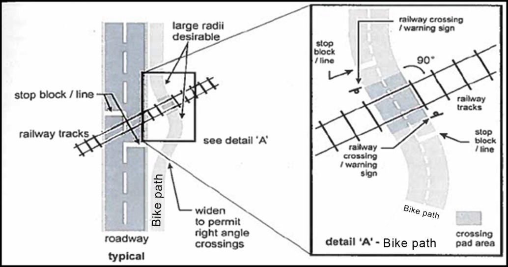
Source: Transportation Association of Canada (TAC), 2017, Geometric Design Guide for Canadian Roads, Chapter 5-Bicycle Integrated Design Figure 5.6.19 pg.67
For figures specific to the required width of the crossing surface, refer to Figure 5-1 and Article 5 of this Grade Crossings Handbook.
The following figures provide examples of typical engineering design options for grade crossings with roads and bicycle lanes, grade crossings with standalone sidewalks, paths or trails, and grade crossings with a sidewalk, path or trail adjacent to the grade crossing.
Note: As provided for under Article 8.2 of this Grade Crossings Handbook, in cases where grade crossing signage cannot be seen from SSD, a “RAILWAY CROSSING AHEAD” sign must be used when the grade crossing is equipped with a Standard Railway Crossing Sign. Furthermore, as provided under Article 18 of this Grade Crossings Handbook, when the grade crossing is equipped with a warning system and the grade crossing warning system cannot be seen from SSD, a “PREPARE TO STOP AT RAILWAY CROSSING” sign must be installed.
For skewed angle grade crossings, it would be recommended to design the sidewalk, pathway, or trail perpendicular within a minimum distance of 5m from the nearest rail to the stop position to provide persons with assistive devices an opportunity to cross at a 90-degree angle.
Also, as provided for in article 13.4.1 of this Grade Crossings Handbook, a sidewalk, path, or trail with a centerline more than 3.6 m (12ft.) from the centre of a nearby warning signal mast must have separate light units for each direction of travel.
Appendix Figure M-6 Example of Typical Grade Crossing with Vehicular Road and Bike Lane
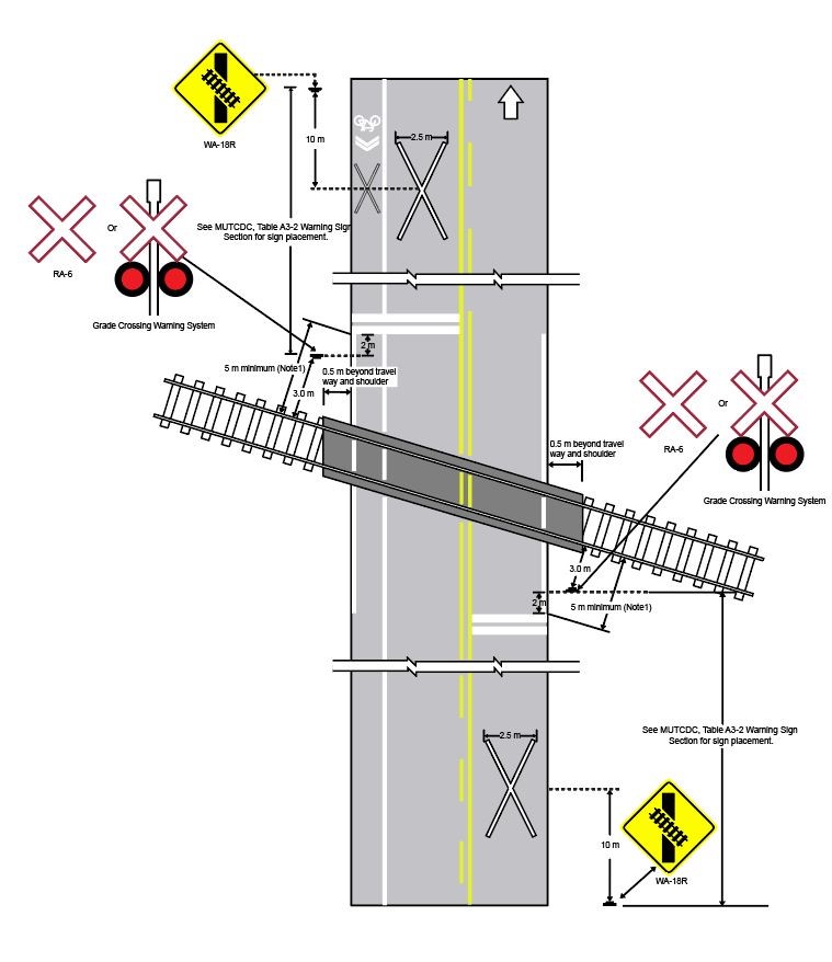
Appendix Figure M-7 Example of Typical Grade Crossing with Stand Alone Sidewalk, Path, or Trail
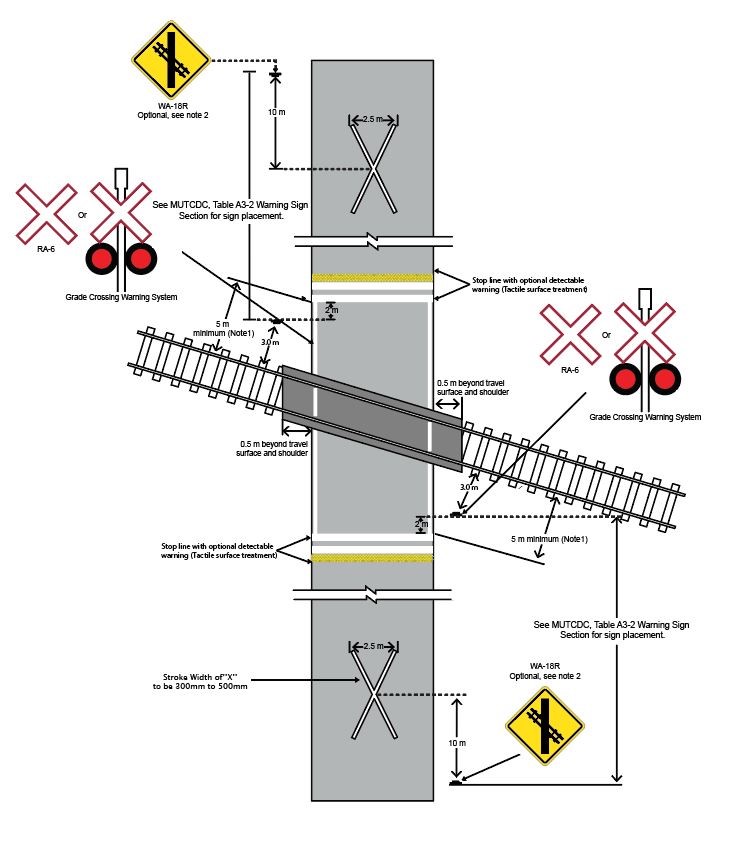
Appendix Figure M-8 Example of Typical Grade Crossing of a Road including a Sidewalk, Path, or Trail
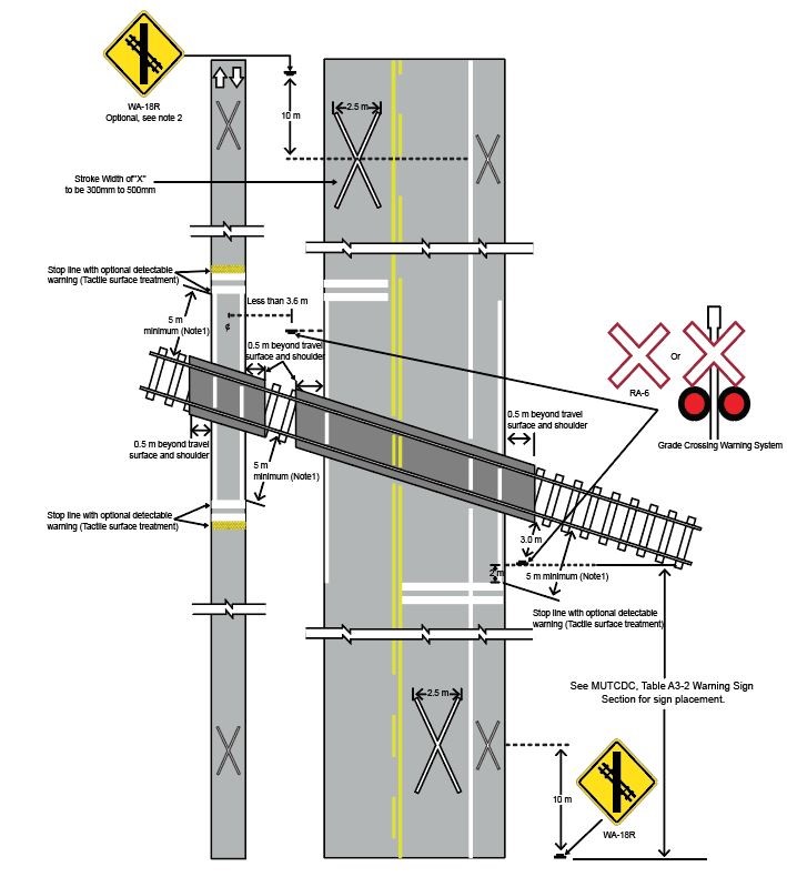
Appendix Figure M-9 Example of Sidewalk Placements Outside of a Grade Crossing Gate (Skewed Angle Crossing)
Source: Figure adapted from MUTCD 2009 Edition
Appendix Figure M-10 Example of a Refuge Area and the use of markings on a Sidewalk Grade Crossing
Source: Figure adapted from MUTCD 2009 Edition.
Appendix Figure M-11 Example of Placement of Pedestrian Gates at a Grade Crossing
Source: Figure adapted from MUTCD 2009 Edition.
Appendix Figure M-12 Example of Placement of Pedestrian Gates at a Sidewalk Grade Crossing
Source: Figure adapted from MUTCD 2009 Edition.
Other Examples of Grade Crossing Design Options
The following figures stem from the United States. While these grade crossing design options may be applicable in the Canadian context, designers must ensure the grade crossing design satisfies the provisions of the Grade Crossings Regulations, and the Grade Crossings Standards. Other best practices should also be followed i.e.,this Grade Crossings Handbook, the Manual of Uniform Traffic Control Devices for Canada (MUTCDC) and the Geometric Design Guide for Canadian Road.
Appendix Figure M-13 Example of Tactile Walking Surface Indicator Treatments
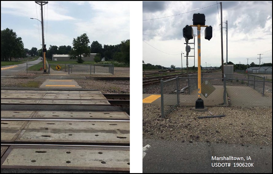
Source: U.S. Department of Transportation, Federal Railroad Administration
Appendix Figure M-14 Example of Gate Skirt Treatment/Emergency Exit
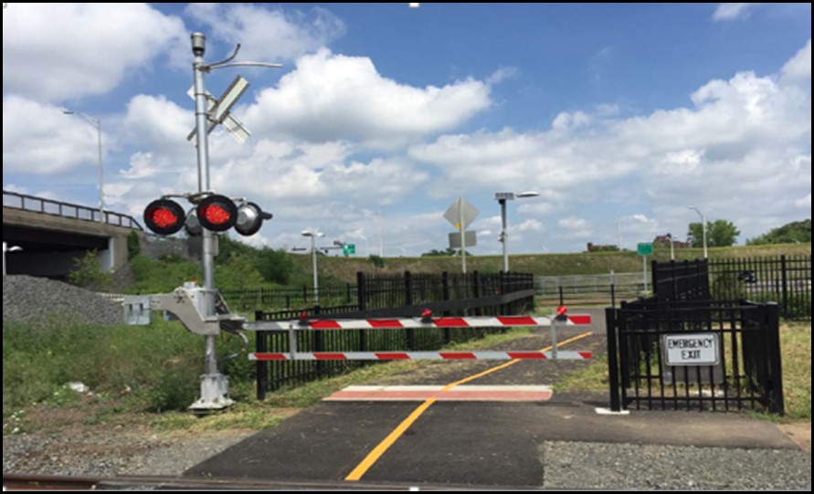
Source: U.S. Department of Transportation, Federal Railroad Administration