
- Article 12 – Warning System Operation
- Article 13 – Number and location of light units
- Article 14 – Light units – Alignment
- Article 15 – Bells and gates
- Article 16 – Circuitry
- Article 17 – Warning systems and traffic signals installed at grade crossings in lieu of a warning system – Inspection and testing
Article 12 - Warning System Operation
12.0.1 Except as otherwise specified in articles 12 to 16 and Appendix B of these Standards, or in the Grade Crossing Regulations, warning systems must be in accordance with the requirements and recommended practices of Part 3 of the AREMA Communications and Signals Manual.
12.0.2 For the purposes of these Standards, the following interpretations and adjustments apply with respect to the AREMA's Communications and Signals Manual of Recommended Practice:
- Any guidelines, recommendations, and similar, are to be considered mandatory.
- Any references to “should” are to be read as “must”.
- The term “highway-rail grade crossing warning system” is to be read as “warning system”.
- The term “railroad” and the phrase “operators of the passenger or commuter rail system” are to be read as “railway company”.
- The term “lights” is to be read as “light units,” unless it refers to gate light units.
- The term “train” is to be read as “railway equipment”.
- The term “roadway” and “roadway approach” are to be read as “road approach”.
The following are to be disregarded:
- All references to the “MUTCD”.
- All “Purpose” Articles; paragraph 2 of Article 3.1.16 G.1(b)(ii); and Article 3.2.35 K.5 of the AREMA.
- All references to and requirements related to the “Diagnostic Team”.
- All references to and requirements related to the “highway agency” or “highway agency or authority with jurisdiction”.
- All references to and requirements related to the “agency” or “public agency”.
- All references to and requirements related to “manufacturers,” except where the requirement is to do something in accordance with the manufacturer's instructions.
- All references to “unless otherwise specified” or “other considerations,” all references to approvals or orders, and any other reference to exercising discretion.
- All purchase order requirements.
- All requirements to create or keep records.
- All requirements for a diagnostic review, an engineering study, a study of train operations, a risk analysis, a safety analysis, and all requirements to provide special instructions, operating rules, orders, or operational procedures.
12.1 Signal Assemblies
Note: All grade crossings installed or modified as of November 28th, 2014, are required to meet these specifications before they can be placed into service. (See Article 2 for more information on amendments to the GCR timelines).
Signal assemblies, gate assemblies and cantilever assemblies at grade crossings that existed before November 28th, 2014, should be as shown in Figure 12-1, Figure 12-2, and Figure 12-3 respectively, and should meet the specifications below. (See Article 2 for more information on amendments to the GCR timelines)
Note: All measurements shown in Figure 12-1 , including the light unit spacing with respect to the center of the mast and the light units; the distance of the Railway Crossing sign and Number of Track sign from the top and bottom of the light unit backgrounds; the clearance line; the foundation height; and the height of the light unit above the crown of the road also apply to Figure 12-2 , Figure 12-3 , Figure 12-4 , Figure 12-5 .
- The minimum clearance distance from the face of a curb to the clearance line must be 625 mm (2 ft).
- Where there is no curb, the minimum clearance distance must be 1.875 m (6 ft) from the edge of the travelled way to the clearance line and a minimum of 625 mm (2 ft) from the outer edge of the road approach shoulder to the clearance line if there is a shoulder.
This clearance distance is provided to allow road users the space required to recover without colliding with any objects in the event of a loss of control, trip or fall, in addition, the horizontal clearance is provided to ensure the required space is available for maintenance equipment (sweeping and snow removal) to prevent potential damages to warning system components.
For additional guidance on minimum clearance distances, refer to Figure 12-6, Figure 12-7, Figure 12-8, Figure 12-9 outlining four typical cases as per Geometric Design Guide for Canadian Roads (TAC).
Note: The minimum clearance distances specified in articles 12.1 (a) and (b) must also be maintained for stand-alone sidewalks, paths, or trails. Also, where sidewalk, paths or trails are installed at a grade crossing with vehicular traffic, a minimum clearance distance applies from the field side edge of a sidewalk, path or trail to the clearance line not less than 625 mm (2 ft) as referenced in Figure 12-4 and Figure 12-5.
- The top of the warning signal foundation must be a maximum of 100 mm (4 in) above the surrounding ground. The slope of the surrounding ground away from the foundation toward the travelled way must not exceed a ratio of 4:1 (AREMA 3.1.35 note:3).
- The gate arm reflective materials shall have
- stripes of 406 mm (16 in) and must be affixed with white and red alternately and be aligned vertically.
Note: Article 12.1(d)(i) applies only to grade crossings constructed as of November 28th, 2014, and to grade crossing that existed before November 28th, 2014, when any of their components are changed (GCR68(1), 82(1), 87(1) and 87(2)). (See Article 2 for more information on amendments to the GCR timelines)
- Retroreflective material must meet the specifications for Type XI, white sheeting, in sections 4 and 6 of ASTM D4956 (cited in Part A), when tested in accordance with the Test Methods for Type XI specified in sections 7 and 9 of that Standard; and
- The retroreflection coefficient of the retroreflective material referred to in (ii) is to be maintained above 50 per cent of the value specified for Type XI, white sheeting, in sections 4 and 6 of ASTM D4956 (cited in Part A).
Note: Sub-articles (ii) and (iii) apply to all grade crossings as of the coming into force of the GCR(GCR58; GCS 4.1.3(2)) (see Article 2 for more information on amendments to the GCR timelines)
- For grade crossings used by vehicles, gate arms must extend to no more than 1 m (3 ft) from the longitudinal axis (edge of farthest lane or travelled way) of the road approach. Where gates are installed on each side of the same road approach, gate ends must extend to within 1 m (3 ft) of each other.
- Where gates are installed at sidewalks, paths, or trails,
- each gate arm must extend across the full width of the sidewalk, path, or trail; and
- in the case of a sidewalk, path or trail that is less than 3.5 m (11.5 ft) wide, two lights are required on each gate arm located so that the lights are over the two points dividing the sidewalk, path, or trail into thirds. The two gate arm lights must flash alternately.
- Where gates are dedicated strictly for sidewalks, paths or trails, the gate height from the crown of the road should be maintained as close as possible to the lower end of the gate height tolerances shown in Figure 12-2 but shall not be installed less than 1.1m (3.5 ft)
- The height of the cantilever assembly clearance must be between 5.2 m (17 ft) and 6.0 m (20 ft) above the crown of the road, as shown in Figure 12-3 (AREMA 3.2.5 C 8).
Figure 12-1 Warning Signal Assemblies
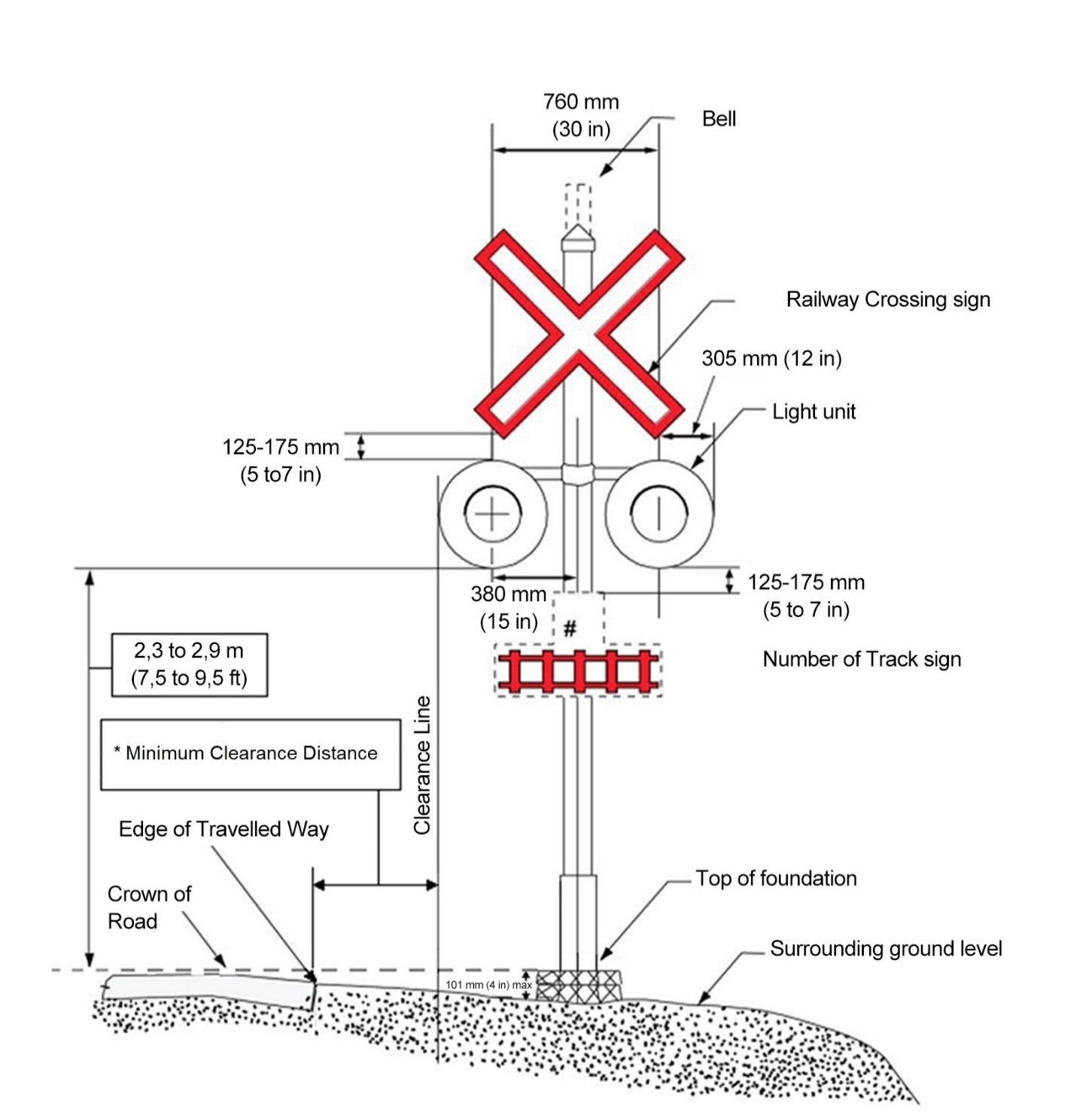
*For minimum clearance distances please refer to article 12.1(a) and (b).
Figure 12-2 Gates
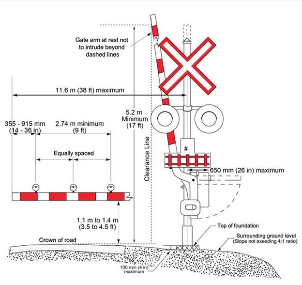
Figure 12-3 Cantilever
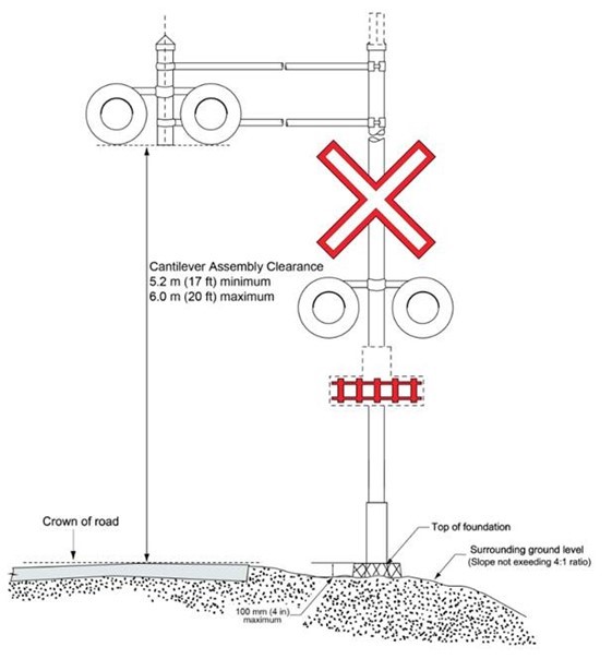
Figure 12-4 Gates with Front Sidewalk
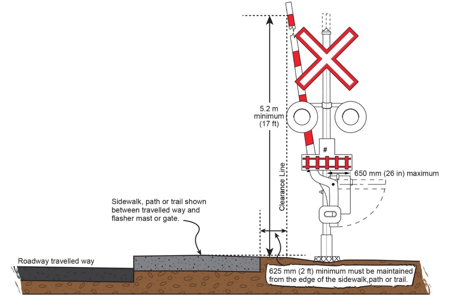
Figure 12-5 Gates with Rear Sidewalk

Figure 12-6 Minimum Clearance Distance with No Shoulders and No Curb or Gutter
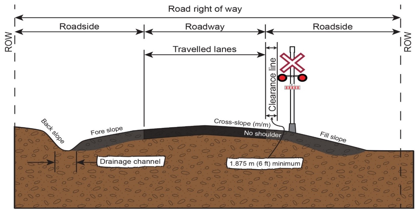
Image is not to scale.
Figure 12-7 Minimum Clearance Distance with Shoulders and No Curb or Gutter
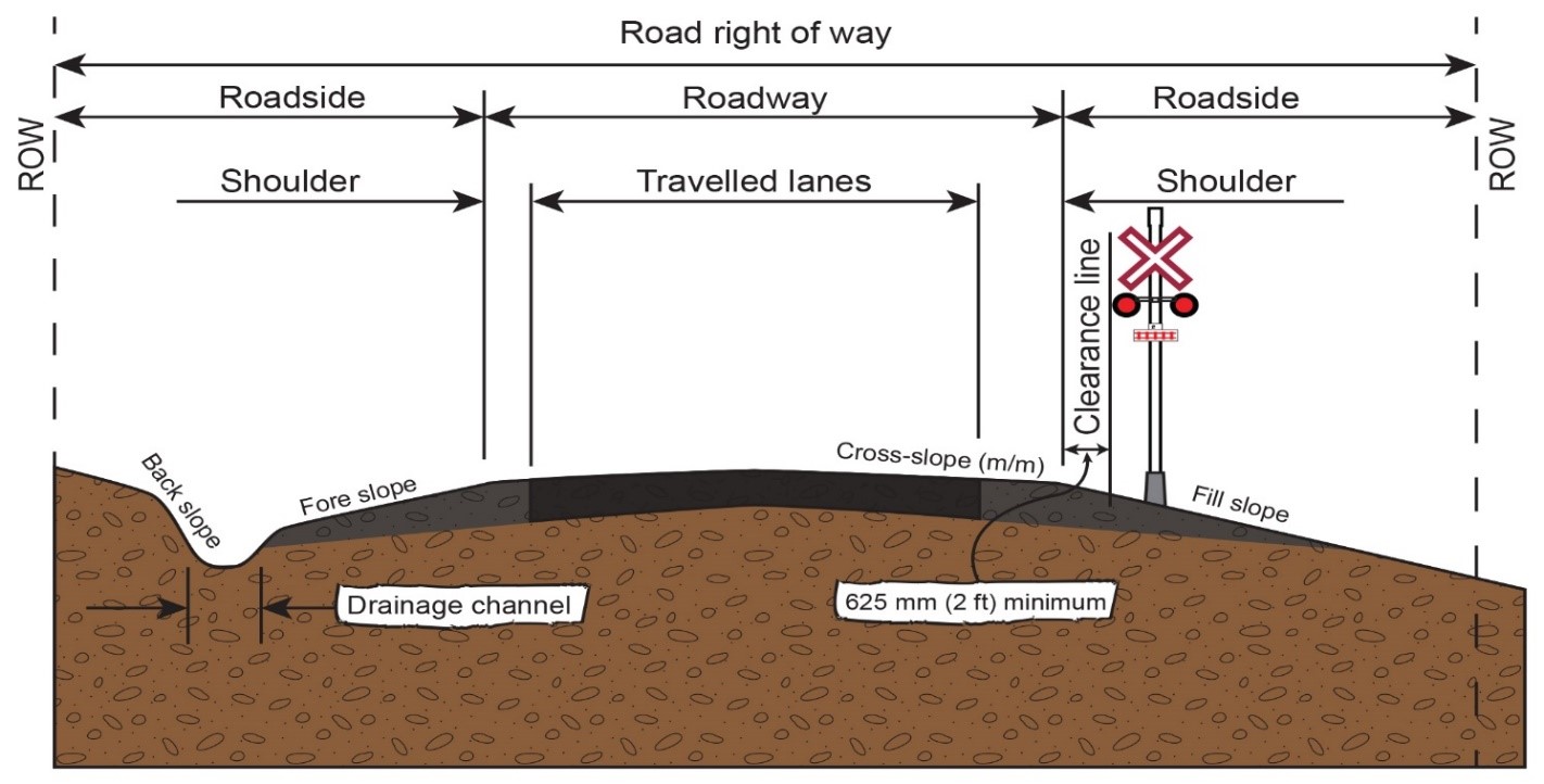
Image is not to scale.
Figure 12-8 Minimum Clearance Distance with Shoulder, Curb, and Mountable Gutter with a Separate Sidewalk, Path, or Trail
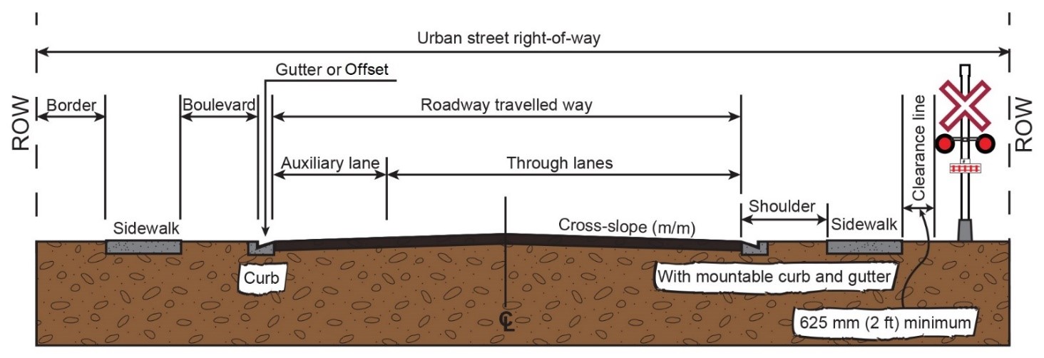
Image is not to scale.
Figure 12-9 Sidewalk, Path, or Trail
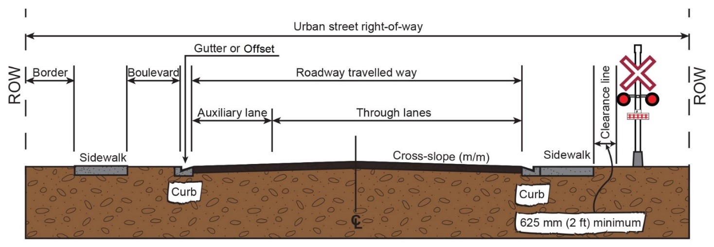
Image is not to scale.
12.2 Recorders
In addition, grade crossing warning systems installed on or after November 28th, 2014, and those installed prior to this date to which warranted changes are made must have monitoring devices that gather and retain the date and time of the following information for a minimum of 30 days (see Article 2 for more information on amendments to the GCR timelines):
- Activation and deactivation of interconnected devices.
- Gates have returned to or have left the vertical position (Gate Up position)
-
Gates have descended to a point [angle of] 10 degrees from the horizontal
(Gate Down position).
- Activation of the warning system test switch.
- Activation and deactivation of all track circuits used in the control of the warning system, including electronic track circuits.
- Activation of the warning system.
- Activation and deactivation of all devices used to control the warning systems at adjacent crossings; and
- Activation and deactivation of all devices used to activate the warning system from a location other than the crossing.
The date and time recorded should be the local time and should be verified at least monthly.
12.3 Control Circuits
All control circuits that affect the safe operation of a warning system must operate in a manner that activates the warning system if there is a failure of a safety-critical component of that system.
12.4 Electromagnetic, Electronic, or Electrical Apparatus
The electromagnetic, electronic, or electrical apparatus of a warning system must be operated and maintained in accordance with the limits within which the system is designed to operate.
12.5 Track Circuits
In the early years of railways, to prevent two trains from using the same section of track at the same time, timetables and train orders were developed. Later, block signal systems were developed to indicate to the locomotive engineer whether a train was ahead in the next “block” of track. These signals were set manually until the development of the track circuit, which sensed the presence of a train in the block and set the signals automatically. The track circuit was designed to be fail-safe, so that if the battery or any wire connections were to fail, or if a rail was broken, a stop signal would be displayed. Blocks of track were separated by insulated joints.
The DC track circuit, shown in Figure 12-10, was the first means used for automatic train detection. It is a relatively simple circuit and is still used in many crossings warning systems and signaling systems today. The maximum length of these circuits is more than adequate to provide the necessary warning time for crossing warning systems, even with today's train speeds.
The rails are used as conductors of energy supplied by a battery. This energy flows through the limiting resistor to one rail, then through another limiting resistor to the coil of the DC relay, and back over the other rail to the battery, thereby completing a simple series circuit. The relay is energized if the continuity of the rails is intact, and no train is present on the circuit between the battery and the relay. The circuits are limited by insulated joints—devices placed between two joining rail sections to electrically isolate the two sections.
Should an insulated joint fail, the circuit's resistance increases, causing the relay to drop and failsafe. Adjacent track circuits should be designed in such a way that on each side of the insulated joints, the battery polarity is staggered, thus providing another form of fail-safe protection if the integrity of the insulated joints is compromised.
Therefore, railway track circuits must:
- detect non-insulated railway equipment axles in any part of the track circuit.
- detect a 0.06-ohm shunt when the shunt is connected across the track rails on any part of the circuit.
- within a turnout, or switch, provide a set of fouling wires that consist of at least two discrete conductors, and must ensure the proper operation of the track circuit when the circuit is shunted. The use of a single duplex wire with a single plug is not permitted.
- in the case of a non-insulated rail joint within the limits of a track circuit, be bonded by means other than joint bars, and the bonds must ensure electrical conductivity; and
- in the case of an insulated rail joint used to separate track circuits, prevent current from flowing between rails separated by the insulation, and be spaced as shown in Figure 12-11, below.
Tests must be made upon the installation of, and when changes or adjustments are made to, the control system or track circuit to ensure that the system is operating as intended (AREMA 3.3.20B 3; GCR94(2)).
When biased relays or two-element, two-position AC relays are used, the polarities of adjacent track circuits should be staggered for feed/relay, relay/relay configuration. In other types of track circuits, the polarities of adjacent circuits may be staggered, as required by the individual railway (AREMA 8.6.1 B 13).
The length of any track circuit (approach or island) should be greater than the maximum inner wheelbase of any railway equipment that may occupy the track circuit, or a minimum of 36.58 m (120 ft), unless other provisions for protection are made. (AREMA 3.1.30, 8.6.1 B 14). See Figure 12-11.
Figure 12-10 DC Track Circuit
Figure 12-11 Recommended Insulated Joint Location for Grade Crossing Island Circuit
a) Island Track Circuit Defined by Insulated Joints
b) Electronic Island Circuit
Bonding and Rail Connectors
Bonding is an essential part of the track circuit. Without continuous conductivity in the rails, the track circuit would be unstable and impossible to adjust properly. It is important to bond all angle bars within the track circuit, as well as to install all track connections at the insulated joints, as indicated in Figure 12-12 and Figure 12-13, to maximize continuity and broken rail protection.
To maintain the integrity of the track connectors, they should be installed on the side of the rail on which the bonding hole was drilled and should not be pounded in excessively. (Bonds that have been pounded in up to the shoulder as indicated in Figure 12-12 should be replaced.)
Figure 12-12 Proper Track Connector Installation
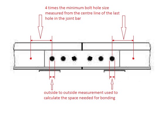
Bonding holes should be drilled at the neutral axis of the rail, approximately midway between the base fillet and head of the rail fillet. Therefore, the location of the bonding hole should be at a minimum distance of four times the minimum track bolt hole size, measured from the centre line of the last hole in the angle bar or insulated joint, as shown below. Drilled bonding holes should also be 3/8 inch in diameter.
Figure 12-13 Proper Bonding Techniques
12.6 Battery Back-up
A battery is a device consisting of two or more electromechanical cells that convert stored chemical energy into electrical energy. Each cell has terminals, or electrodes: a positive electrode, or cathode, and a negative electrode, or anode. The terminal marked positive has greater electrical potential energy than the terminal marked negative. The terminal marked positive is the source of electrons that, when connected to an external circuit, will flow and deliver energy to an external device. Connecting the battery to an external circuit causes the ions to move within the cell, causing chemical reactions at each of the terminals. These reactions produce electrical energy that is supplied to the external circuit. It is the movement of the ions in the battery that allows current to flow out of the battery to perform work. Although the term battery technically means a device with multiple cells, individual cells are also popularly called batteries. Railways use several different makes and models of batteries, provided by many different manufacturers.
Secondary batteries can be discharged and recharged multiple times, as the original charge of the electrodes is restored by reverse current.
The requirement to provide warning system battery back-up for 8 hours of continuous activation and 24 hours of normal railway operations, applies to grade crossings installed after November 28th, 2014 (GCR 44), and when changes are made to grade crossings installed after that date (GCR 87).
Items that could be considered when determining the required battery back-up Amp hour (AH) rating are as follows:
- Number of railway equipment moves that activate the warning system
- Length of all railway equipment moves
- Speed of railway equipment which activates the warning system.
- Minimum designed warning time.
- Duration for which the warning system will operate for each railway equipment move.
- Current draw of the activated warning system components; and
- Current draw of all control equipment in its normal state.
12.6.1 Types of railway batteries in the field
The batteries used by railways include the following.
Secondary – Rechargeable (can be reused repeatedly (storage))
Some examples are:
- Lead-acid (all types)
- Nickel-iron (wet)
- Nickel-cadmium (all types)
- Nickel metal hydride (all types)
- Silver-oxide (dry)
- Lithium-ion
- Lithium-polymer
Primary – Non-rechargeable (can be used one time only)
Some examples are:
- Carbon
- Alkaline (all types)
- Lithium
- Zinc (all types)
- Mercury
Batteries not used within a reasonable length of time should be given a charge periodically, and if the specific gravity of the battery's electrolyte drops below 1.180, the battery should be recharged as per the manufacturer's instructions.
Electrolyte lost due to spillage should be replaced with the proper amount of electrolyte of the same specific gravity as that of the battery's other cells. Electrolyte should not be added under any other circumstances. As a temporary, emergency measure only, if the electrolyte level is below the top of the plates, add water to prevent the plates from becoming dry.
Freshly mixed electrolyte should not be placed the in cells until it has cooled.
12.7 Power-Off Light
A Power Off light is a steady-lit, white LED or incandescent lamp located on the external housing of the signal bungalow or on a post which indicates to train crew and employees that the crossing is operating under normal conditions. When the Power Off light is extinguished or flashing, the railway authority is responsible for reporting and attending to the situation.
Article 13 - Number and Location of Light Units
Note: This is a requirement for new grade crossings equipped with a warning system. Existing grade crossings have until November 28th, 2022, or November 28th, 2024, depending on the specific physical and operational characteristics of the grade crossing, to comply with this requirement, unless they undergo a change before then (GCR 44, 53, 68, 82 and 87) (See Article 2 for more information on amendments to the GCR timelines).
13.0 Incandescent Lights
Where incandescent lights are installed, the light unit voltage must be maintained between 90 and 110 per cent of the rated voltage under standby power conditions.
13.1 Light Unit Visibility for Crossing Users
Light units must be installed as part of a warning system in such a location as to ensure that the crossing user in each land of a road approach, or accessing a road approach,
- is within the effective distribution range of luminous intensity of a set of light units within the distances specified for the front light units within the SSD; and
- can see at least one set of front light units clearly.
13.2 Light Unit Visibility for Crossing Users in a Stopped Position
Except when the visibility of units is obstructed by railway equipment, light units must be provided in a warning system in such a location as to ensure that a crossing user in the stopped position at the grade crossing,
- is within the effective distribution pattern of luminous intensity of a set of back lights (e.g., those lights on the far side of the tracks, for approaching traffic); and
- so that at least one set of back lights is clearly visible to crossing users in each lane.
13.3 Cantilevered Light Units
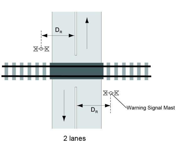
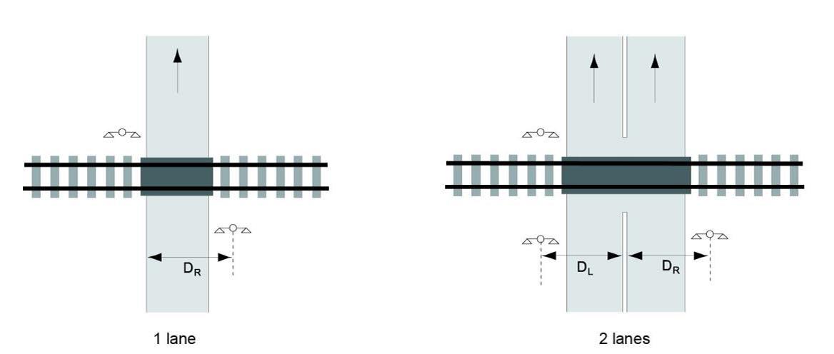
13.3.1 Except on a one-way road, or a roadway with a center median, where a second warning signal is installed on the left side of the lane, a cantilevered light unit must be provided in a warning system if:
- the distance between the center of a warning signal mast and the edge of the lane of the road that is the farthest from the mast, measured perpendicular to the road, exceeds
7.7 m for DR, or 8.7 m for DL, as shown in Figure 13-1: or
- the front light units of the warning signal (e.g., those on the same side of the track as approaching traffic) are not clearly visible within the distance for the set of light units as specified in Article 14.4.
13.3.2 Cantilevered light units must be installed for a warning system on a road that meets the specifications for an expressway as specified in Table 10-4.
Note: Cantilevered light units are most appropriate for vehicular traffic; however, there may be a need for them along wide sidewalks, paths, or trails.
Figure 13-1 Warning Signal Offsets Requiring Cantilevered Light Units
a) Two-Way Road
b) One-Way or Divided Road
13.4 Light Units for a Sidewalk, Path, or Trail
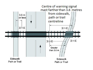
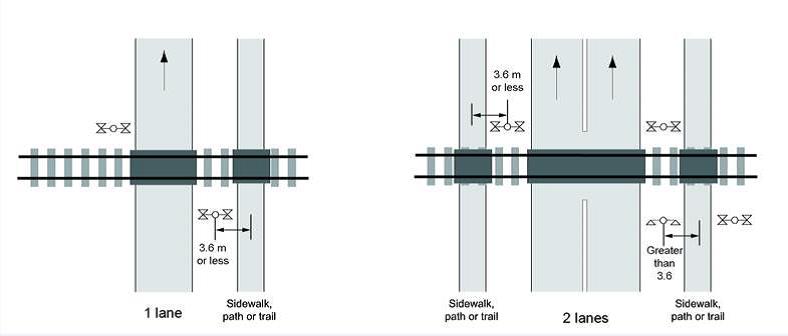
13.4.1 A sidewalk, path, or trail with a centreline more than 3.6 m (12 ft) from the centre of a warning system signal mast must have separate light units for each direction of travel, as shown in Figure 13-2 a).
Note: This distance is measured from the center of the warning system signal mast located on the same side as the sidewalk path or trail.
13.4.2 Lights must be installed for persons travelling in the direction opposite to vehicle traffic where there is a sidewalk, path or trail along a one-way road as shown in Figure 13-2 b).
Figure 13-2 Sidewalks, Paths, and Trails
a) Two-Way Road
b) One-Way Road
13.5 Vertical and Horizontal Cones of Vision
The effectiveness of a grade crossing warning system depends on the capability of the warning system lights to attract the attention of a driver looking ahead along the road approach.
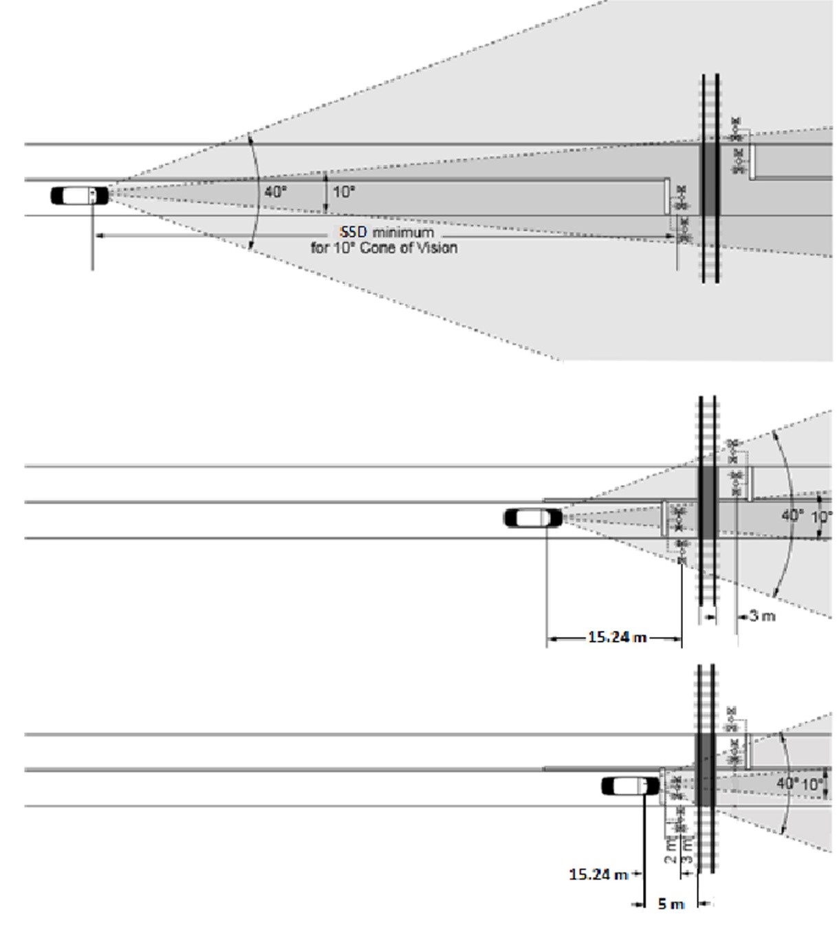
Cone of vision describes the driver's lateral vision. A driver has excellent lateral vision at up to 5 degrees on each side of the centre line of the eye position (a cone of 10 degrees) and adequate lateral vision at up to 20 degrees on each side. Figure 13-3 illustrates the horizontal cone of vision for drivers approaching and stopped at a grade crossing.
Figure 13-3 Horizontal Cone of Vision
The driver's vertical vision is limited by the top of the windshield, resulting in a need for overhead light units at a minimum height of 5.2 m, placed at least 15 m in advance of the stopped position for vehicles. Figure 13-4 illustrates the vertical limits.
Figure 13-4 Vertical Vison Limits
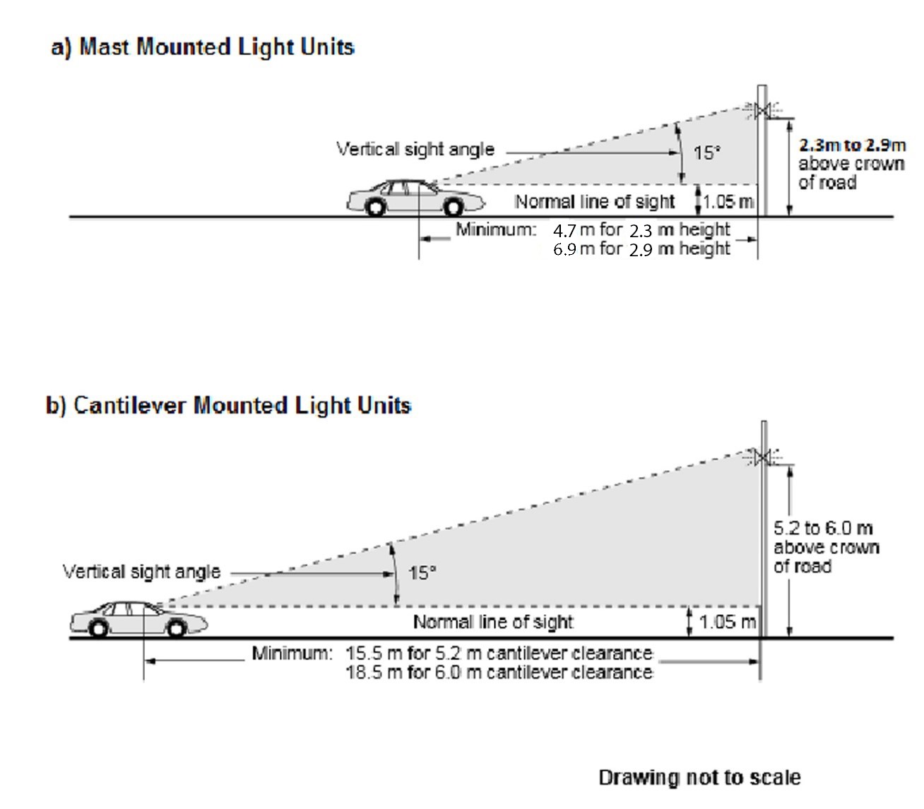
Note: The vertical cone of vision is limited to 15° by the top of the windshield.
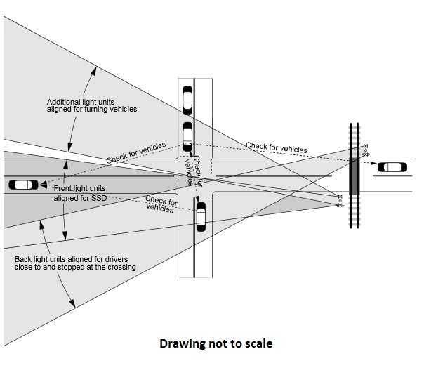
The number and positioning of light units may be affected by the horizontal and vertical curvature of the road approach, the proximity of intersecting roads and entranceways, and the width of the road at the crossing. See Figure 13-5 for a representation of light units positioned for visibility for all approaching vehicles.
Figure 13-5 Typical Light Unit Arrangement for an Adjacent Intersection
Article 14 - Light Units – Alignment
For grade crossing warning systems to be effective, the light units must be visible to road users in a manner that allows them to stop safely before a train arrives. in terms of grade crossings, therefore, visibility is defined as the distance in advance of the stop line or vehicle stop position to a point known as the stopping sight distance (SSD) over which a set of front light units must be continuously visible from and within SSD.
Sets of primary front light units on the warning signal, intermediate lights, and on a cantilever structure, where provided, must be aligned as described below.
14.1 General – Light Units
The following applies to new grade crossings, and to existing crossings to which a change is made to any component (GCR68(1), 82(1), 87(1) and 87(2)). (See Article 2 for more information on amendments to the GCR timelines)
14.1.1 Light units must be of a 200-mm or 300-mm light emitting diode (LED) signal module type and as specified in Appendix A to this document.
14.1.2 Sets of light units of warning systems must flash alternately and uniformly at a rate of 45 to 65 flashes per minute.
14.2 Alignment Height – Front and Back Lights for Vehicles
Articles 14.2 to 14.6 apply to new grade crossings immediately, and to existing grade crossings by November 28th, 2022, or November 28th, 2024, depending on the specific physical and operational characteristics of the grade crossing, and if a change is made to any component (GCR68(2), 82(2), 87(1) and 87(2)). (See Article 2 for more information on amendments to the GCR timelines):
14.2.1 Light units must be aligned so that their axis passes through a point 1.6 m above the road surface at the SSD.
Note: If this is not possible, a Prepare to Stop at Railway Crossing sign must be installed. See Article 18 or information (GCR 67 and 81(1)).
14.3 Alignment Distance – Front Light Units for Vehicles
14.3.1 Front light units must be aligned through the center of the approaching traffic lane for which they are intended, as follows:
- at a minimum, to the stopping sight distance; or
- to the point at which the light units are first visible, if this point is less than the distance specified in (a).
14.4 Alignment – Intermediate Front Light Units for Vehicles
14.4.1 Additional sets of light units must be aligned to cover any intermediate areas of the road approaches between the coverage provided by the front light units, aligned as required in Article 14.3, and the back light units, aligned as required in Article 14.5.
14.4.2 Additional sets of light units provided for a crossing user must be aligned through the point that is 1.6 m above the surface of the road at the point at which the crossing user enters the road approach.
14.5 Alignment – Back Light Units for Vehicles
14.5.1 Back light units, intended for road users approaching the grade crossing from a lane on the opposite side of the line of railway from the warning signal on which they are installed, must be aligned through the center of that lane, 15 m in advance of the warning signal for that side of the line of railway.
14.6 Alignment – Light Units Installed Exclusively for Sidewalks, Paths, or Trails
14.6.1 Light units installed exclusively for sidewalks, paths or trails must be aligned so as to be visible through a point 1.6 m above the center of the sidewalk, path or trail and 30 m (100 ft) in advance of the nearest rail on both sides of the line of railway or at the point at which the set of lights units first become visible, if less than 30 m (100 ft).
Article 15 - Bells and Gates
15.1 Bells
The following applies to new grade crossings, and to existing crossings at which a change is made to any component [GCR 44, 53, 68(1), 82(1), 87(1) and 87(2)].
A crossing warning bell is an audible warning device used to supplement other active devices, such as light units and gates. A bell is an effective means to warn pedestrians, cyclists or person using assistive devices.
When used, the bell is usually mounted on top of one of the signal support masts.
There are several different types of bells installed at Railway Crossings across the country, each with its own requirements regarding decibel levels. For example, an electronic or electromechanical loud-tone bell must not be louder than 105 dB(A) and not quieter than 85 dB(A). However, an electronic or electromechanical soft-tone bell must operate at not more than 85 dB(A) and not less than 75 dB(A). See Articles 3.2.60 and 3.2.61 of the AREMA Communications and Signals Manual for the recommended design criteria for bells.
15.1.1 A bell is required as part of all warning systems except the limited-use warning systems referred to in Appendix B and the limited-use warning systems with walk lights referred to in Appendix C.
15.1.2 Where there is only one sidewalk, path or trail along a road approach, the bell must be located on the signal mast adjacent to the sidewalk, path, or trail.
15.1.3 A bell is required on a signal mast adjacent to a sidewalk, path or trail if separated from any other signal mast with a bell by more than 30 m (100 ft).
15.1.4 All bells must continue to operate for the same duration as the light units.
15.2 Gates
Warning system gates are designed to restrict access to a grade crossing temporarily during the passage of railway equipment or in the event of a failure. They typically consist of a moveable automatic gate arm, a locking assembly and a housing containing the electromechanical components that lower and raise the arm. The arm and locking assembly are bolted to a concrete or steel foundation, which holds the lowered or raised gate arm in place during normal operation.
15.2.1 The gate arm should be installed perpendicular to the longitudinal axis of the road approach.
15.2.2 The descent of the gate arm must take 10 to 15 seconds and its ascent must take 6 to 12 seconds (AREMA 3.2.15 U 2, 3.2.15 U 1a and 3.3.30 D 5).
15.2.3 The gate arm must begin its descent once the gate arm clearance time has elapsed, calculated in accordance with article 10.4 of the GCS and this document (AREMA 3.3.30 D 3).
15.2.4 For a grade crossing where railway equipment enters the grade crossing at over 25 km/h (15 mph), the gate arm must be in the horizontal position at least 5 seconds before the arrival at the crossing surface of railway equipment (AREMA 3.3.30 D 4).
15.2.4.1 For a grade crossing where the railway equipment enters the grade crossing at a speed of 25 km/h (15 mph) or less, the gate arm must be in the horizontal position when the railway equipment arrives at the crossing surface.
15.2.5 The gate arms must operate uniformly, smoothly, and without rebound, and must be held securely when in the raised position (AREMA 3.2.15 U 5).
15.2.6 If a gate arm strikes or fouls any object during its ascent or descent, it must readily stop and, on removal of the obstruction, assume the position corresponding with the control apparatus (AREMA 3.2.15 U 7).
15.2.7 Where gates are located in the median, additional width may be required to provide minimum clearance for the high-wind gate arm support bracket (AREMA 3.1.35(4)).
15.2.8 Means should be provided to rotate the gate mechanism 90 degrees, or easily disconnect the gate arm from gate arm support, for servicing (AREMA 3.2.15 G 7).
15.2.9 Means should be provided to prevent damage to the mechanism from varying load conditions due to weather when the gate is descending or by the counterbalancing device driving it to the clear position in the event of a broken gate arm (AREMA 3.2.15 U 4).
Article 16 - Circuitry
Warning systems' circuitry design must adhere to section 11 of the RSA, which stipulates that all work relating to railway works must be done in accordance with sound engineering principles and that all related engineering work must be approved by a professional engineer (RSA 11(1) and 11(2)).
16.1 Warning Time
Section 26.2 of the RSA states that “The users of a road shall give way to railway equipment at a road crossing if adequate warning of its approach is given.” In cases where sightlines are not provided, and traffic volumes are high, with multiple tracks traversing the location, the greater the need for reliable warning devices. Failure to provide adequate warning of approaching railway equipment can create a hazardous situation in which the risk of a vehicle-train collision increases.
16.1.1 The time during which the warning system must operate before the arrival of railway equipment at the crossing surface must be the greatest of
- 20 seconds, unless the grade crossing clearance distance (Figure 10-1) is greater than 11 m (35 ft), in which case the duration must be increased by one second for each additional 3 m (10 ft) or fraction thereof (GCS 16.1.1(a); AREMA 3.3.10 B 2(a)).
- the departure time for the design vehicle (GCS 10.3.2).
- the departure time for pedestrians, cyclists, and persons using assistive devices (GCS 10.3.3).
- the gate arm clearance time plus the time to complete the gate arm descent, plus 5 seconds.
- the minimum warning time required for traffic signal interconnection, as specified in GCS 19.1; or
- the time for the design vehicle to travel from the stopping sight distance and pass completely through the clearance distance.
16.2 Consistency of Warning Times
16.2.1 Operating control circuits must provide consistent warning times for railway equipment regularly operating over the grade crossing.
Note: This is a requirement for new grade crossings with a warning system and for existing grade crossings when a warranted change is made.
16.2.2 Where the maximum railway operating speed has been reduced, the approach warning times for railway equipment regularly operating over the grade crossing must not be more than 13 seconds longer than the warning time for the railway design speed.
Note: Article 16.2.2 is a requirement for new grade crossings with a warning system and, as of November 28th, 2022, or November 28th, 2024 for existing grade crossings, where the maximum railway operating speed has been reduced (See Article 2 for more information on amendments to the GCR timelines)
16.2.3 Where a grade crossing has more than one line of railway, consideration should be given to operation of the warning system or traffic control devices when a second train approaches following the passage of the first train.
Considerations may include the use of an “extended hold” to ensure that the crossing gates remain down until the second train has arrived at the crossing surface, active second train event signs can also be installed in addition to the “extended hold”, as well as the use of traffic signal controller logic, which can assure that a second track clearance can be provided in the event the gates have been raised prior to the arrival of a second train where interconnected traffic signals are installed.
16.3 Cut-Outs
Note: This is a requirement for new grade crossings with a warning system and grade crossings at which a warranted change is made and, as of November 28th, 2022, or November 28th, 2024 for all grade crossings (See Article 2 for more information on amendments to the GCR timelines)
16.3.1 Where railway equipment regularly stops, or railway equipment is left standing, within the activating limits of a warning system, the warning system must be equipped with a control feature to minimize the operation of the warning system.
16.3.2 A switch, when equipped with a switch circuit controller connected to the point and interconnected with the warning system circuitry, must cut out only when the switch point is within 12.7 mm (half an inch) of the full-reverse position.
16.4 Directional Stick Circuits
Note: This is a requirement for new grade crossings with a warning system and for existing crossings at which a change is made to the directional stick circuitry and, by November 28th, 2022, or November 28th, 2024 for all grade crossings (See Article 2 for more information on amendments to the GCR timelines)
16.4.1 Where a warning system is equipped with directional stick circuits, each circuit
- must include a stick release timer to activate the warning system after a pre-set interval of time in the event of the failure of an approach circuit; or
- when centralized traffic control (CTC) or automatic block signals (ABS) are used, should cause a train control signal system to restrict railway equipment speed to 25 km/h (15 mph) or less, and include a stick release timer.
When CTC or ABS are used, the stick release timer should be programed to 75 per cent of the amount of time it takes for railway equipment travelling at maximum railway operating speed to reach the grade crossing from one direction or the other, whichever is the lesser, measured from the closest control location, interlocking, spur or electric switch lock.
16.5 Identification
16.5.1 Each wire in all housings, including switch circuit controllers and terminal or junction boxes, must be identified at each terminal, and the identification must not interfere with moving parts of the warning system. Material used for identification purposes must be made of insulating material. This requirement does not apply to light units or wiring that is an internal part of solid-state equipment. (GCR16.5.1)
Note: This applies to all grade crossings (new and existing), as it is a maintenance requirement since November 28th, 2014 (GCR93(2); GCS 16.5 and AREMA 3.3.1 D 2) (See Article 2 for more information on amendments to the GCR timelines).
Article 17 - Warning Systems and Traffic Signals Installed at Grade Crossings in lieu of a Warning System – Inspection and Testing
A warning system or traffic control device that is interconnected with a warning system must be maintained, inspected, and tested in accordance with Article 17 of the GCS. Railway companies will also be required to keep records of inspections and testing, as well as a record of warning system malfunctions or failures, for a minimum of two years. (See Article 21 for more details on record-keeping.)
Except as otherwise specified in articles 12 to 16 of the GCS or sections 95 and 96 of the GCR, new and existing warning systems must be inspected and tested in accordance with the requirements and recommended practices of Part 3 of the AREMA Communications and Signals Manual at the frequency specified in tables 17-1, 17-2 and 20-1 of the GCS (GCR 3(2)).
Maintenance, inspection and testing of warning systems must be done in accordance with Articles 3.3.1 and 3.1.15 of the AREMA Communications and Signals Manual.
Inspection and testing of traffic signals installed at a grade crossing in lieu of a warning system must be done in accordance with the road authority's procedures.
|
Designated Frequency |
Definition |
Maximum interval between each inspection or test |
|---|---|---|
|
Weekly |
Once every week (Sunday to Saturday) |
10 clear days |
|
Monthly |
Once every calendar month |
40 clear days |
|
Quarterly |
Once every 3 months (January to March, April to June, July to September, and October to December) |
100 clear days |
|
Twice annually |
Once every 6 months (January to June and July to December) |
200 clear days |
|
Annually |
Once every calendar year |
13 months |
|
Every 2 years |
Once every 2 calendar years |
26 months |
|
Every 4 years |
Once every 4 calendar years |
52 months |
|
Every 10 years |
Once every 10 calendar years |
130 months |
|
Item |
Elements: Inspection and testing requirements |
Frequency for warning systems and traffic signals installed at a grade crossing in lieu of a warning system |
Frequency for limited - use warning systems |
Frequency for limited - use warning systems with walk light |
|---|---|---|---|---|
|
1 |
Warning Systems: for operation of lights, bell, gates, and power-off light |
Weekly or no more than 7 days before the operation of railway equipment |
N/A |
N/A |
|
2 |
Light units: for misalignment, physical damage, and conspicuity |
Monthly |
Quarterly |
Quarterly |
|
3 |
Standby power: for operating bank voltage |
Monthly |
Quarterly |
Quarterly |
|
4 |
Light units, and gates: for damage, cleanliness, and visibility |
Monthly |
Quarterly |
N/A |
|
5 |
Bell: for operation |
Monthly |
N/A |
N/A |
|
6 |
Gate arm: for operation |
Monthly |
N/A |
N/A |
|
7 |
Surge protection: for condition |
Monthly |
Quarterly |
Quarterly |
|
8 |
Circuits: for grounds |
Monthly |
Quarterly |
Quarterly |
|
9 |
Battery: for isolation faults |
Monthly |
Quarterly |
Quarterly |
|
10 |
Batteries: for voltage, current, electrolyte level, and plate deterioration where plates are visible |
Monthly |
Quarterly |
Quarterly |
|
11 |
Interconnection components: for energization of circuits as intended |
Monthly |
N/A |
N/A |
|
12 |
Switch circuit controller: for adjustment |
Quarterly |
Quarterly |
Quarterly |
|
13 |
Batteries: for degree of exhaustion, voltage and current |
Quarterly |
Quarterly |
Quarterly |
|
14 |
Fouling circuits: for continuity |
Quarterly |
Quarterly |
Quarterly |
|
15 |
Direct current relays: for condition |
Semi-annually |
Semi-annually |
Semi-annually |
|
16 |
Bond wires, track connections, insulated joints, and other insulated track appliances: for condition |
Semi-annually |
Semi-annually |
Semi-annually |
|
17 |
Cut-out circuits (any circuit that overrides the operation of a warning system): for operation |
Semi-annually |
Semi-annually |
Semi-annually |
|
18 |
Gate mechanism and circuit controller: visual inspection of condition |
Semi-annually |
N/A |
N/A |
|
19 |
Control circuits operation of traffic signals installed at a grade crossing in lieu of a warning system |
Semi-annually |
N/A |
N/A |
|
20 |
Light units: for proper alignment, focus, and visibility |
Annually |
Annually |
Annually |
|
21 |
Light Unit: for voltage |
Annually |
Annually |
Annually |
|
22 |
Track circuits: for proper functioning |
Annually |
Annually |
Annually |
|
23 |
Flash controller: for flash rate |
Annually |
Annually |
Annually |
|
24 |
Battery: load test |
Annually |
Annually |
Annually |
|
25 |
Warning time: for required time |
Annually |
Annually |
Annually |
|
26 |
Electronic railway equipment detection devices, including processor-based systems: for programming and function ability |
Annually |
Annually |
Annually |
|
27 |
Timing relays and timing devices: for required time |
Annually |
Annually |
Annually |
|
28 |
Cable and wire entrances: for condition |
Annually |
Annually |
Annually |
|
29 |
Switch circuit controller centering device: for condition |
Annually |
Annually |
Annually |
|
30 |
Interconnection operation between of warning systems and traffic control devices |
Annually |
N/A |
N/A |
|
31 |
Pole line and attachments: for condition |
Every 2 years |
Every 2 years |
Every 2 years |
|
32 |
DC polar, AC vane, and mechanical timer relays: for electrical values and operating characteristics |
Every 2 years |
Every 2 years |
Every 2 years |
|
33 |
Gate mechanism: for electrical values, mechanical clearances, and torque |
Every 4 years |
Every 4 years |
Every 4 years |
|
34 |
Relays that affect the proper functioning of a warning system (except for DC polar, AC vane and mechanical timer): for electrical values and operation |
Every 4 years |
Every 4 years |
Every 4 years |
|
35 |
Ground: for resistance value |
Every 10 years |
Every 10 years |
Every 10 years |
|
36 |
Wire and cable insulation: for resistance |
Every 10 years |
N/A |
N/A |
Note: See Appendix J and Appendix L for details pertaining to each test requirement outlined in this table.