Transport Publication - TP 15163 E (2015)
- Table of Contents
- Document Information
- 1.0 Introduction
- 2.0 Application
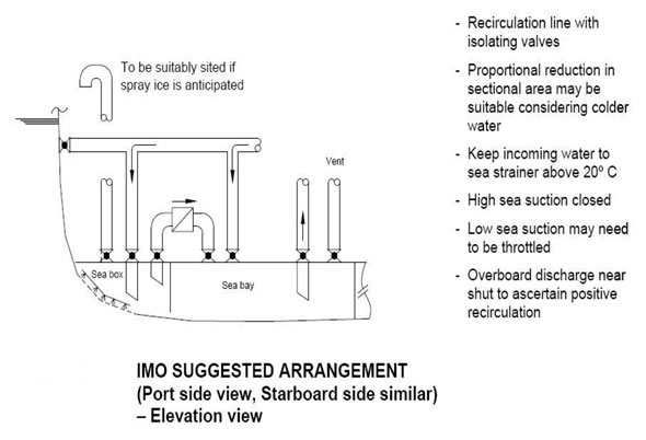
- 3.0 Ice Control Zones
- 4.0 Guidelines to be Onboard
- 5.0 Ice Advisor
- 6.0 Vessel Reporting
- 7.0 Compliance
- 8.0 Operational Practices
- 9.0 List of Appendices to these Guidelines
- 10.0 Publications Required to be Carried
- 11.0 Recommended References - Regulations - Publications
- 12.0 Transport Canada Ship Safety Bulletins
- Appendix A
- Appendix B
MSC/Circ. 504
1. Casualty Records indicate that ships that are not designed to classification rules for navigation in ice and that operate in slush ice conditions are prone to blockage of the sea water cooling intakes and related air vents by slush and/or spray ice. Such blockage has resulted in loss of cooling water to the ship's main engine and/or generators, as well as structura damage to air vents or tanks upon continued operation of water pumps after vent blockage. Incidents have ranged from minor vessel delays to complete power failures which, in some cases, have resulted in groundings.
2. It is common practice to provide a supply of low pressure steam or compressed air to maintain clear cooling water intakes. However, experience has shown that such arrangements will not maintain clear inlets on ships operating in anything but the lightest ice conditions.
3. The following guidelines provide a suitable method to ensure that cooling water flow is maintained to the ship's engine and/or generator under such conditions.
3.1 The ship should be provided with at least one sea bay from which pumps supplying cooling water to essentia machinery can draw.
3.2 The sea bay should:
3.2.1 be supplied with water from at least two sea inlet hoses;
3.2.2 be connected to the sea inlet boxes by pipes, valves and strainers with a cross sectional area at least equal to the tota area of the suctions served by the sea bay; and
3.2.3 be vented to atmosphere by valved pipe of sufficient size to prevent tank over pressurization or under pressurization. 3.3. The sea inlet boxes should:
3.3.1 Be fitted on each side of the ship;
3.3.2 Be as deeply submerged as possible;
3.3.3 Have an area open to the sea of at least five times the total area of the pump suctions served by the sea bay;
3.3.4 Be fitted with a strainer plate at the ship's side having perforations approximately 20 mm diameter to prevent ingress of large ice particles;
3.3.5 Be fitted with a low pressure steam connection for clearing the ice strainer;
3.3.6 Have the vent pipe from the sea inlet sized to prevent ice blockage in the suction piping. On small installations, the cross sectional area should be at least equal to that of the suction piping. In the case of larger installations, the ratio may be reduced, but the minimum diameter recommended is 150 mm. The valve fitted should be of a full flow type; and
3.3.7 Have the valves meet the requirements of SOLAS regulation 11-1/48.3, protection against flooding, when used in unattended machinery space applications.
3.4 Diversion valves and piping should be provided at overboard cooling water discharges to permit warm water to be returned to the sea inlet boxes preventing ice blockages, and also to the sea bay to permit circulation in the event of total sea box blockage by ice.
4. Certain operating areas are noted for heavy spray ice accumulation during winter and precautions should be taken to avoid structural damage due to blockage of air pipes by spray ice. Air pipes serving cooling systems should be positioned in protected areas or heat traced as a preventative measure.
5. The attached sketch illustrates the layout of a recommended system.
